EP1334053B1 - Faltmechanismus für einen zweiteiligen endlosförderer - Google Patents
Faltmechanismus für einen zweiteiligen endlosförderer Download PDFInfo
- Publication number
- EP1334053B1 EP1334053B1 EP01980684A EP01980684A EP1334053B1 EP 1334053 B1 EP1334053 B1 EP 1334053B1 EP 01980684 A EP01980684 A EP 01980684A EP 01980684 A EP01980684 A EP 01980684A EP 1334053 B1 EP1334053 B1 EP 1334053B1
- Authority
- EP
- European Patent Office
- Prior art keywords
- conveyor
- folding mechanism
- parts
- operative
- coupling block
- Prior art date
- Legal status (The legal status is an assumption and is not a legal conclusion. Google has not performed a legal analysis and makes no representation as to the accuracy of the status listed.)
- Expired - Lifetime
Links
- 230000007246 mechanism Effects 0.000 title claims abstract description 18
- 230000008878 coupling Effects 0.000 claims abstract description 16
- 238000010168 coupling process Methods 0.000 claims abstract description 16
- 238000005859 coupling reaction Methods 0.000 claims abstract description 16
- 238000012545 processing Methods 0.000 claims description 3
- 238000012216 screening Methods 0.000 description 8
- 230000008901 benefit Effects 0.000 description 2
- 230000008021 deposition Effects 0.000 description 2
- 238000013461 design Methods 0.000 description 2
- 230000002349 favourable effect Effects 0.000 description 2
- 230000015572 biosynthetic process Effects 0.000 description 1
- 238000010276 construction Methods 0.000 description 1
- 230000000694 effects Effects 0.000 description 1
- 230000005484 gravity Effects 0.000 description 1
- 238000000034 method Methods 0.000 description 1
- 230000008569 process Effects 0.000 description 1
- 230000009467 reduction Effects 0.000 description 1
- 238000012546 transfer Methods 0.000 description 1
Images
Classifications
-
- B—PERFORMING OPERATIONS; TRANSPORTING
- B65—CONVEYING; PACKING; STORING; HANDLING THIN OR FILAMENTARY MATERIAL
- B65G—TRANSPORT OR STORAGE DEVICES, e.g. CONVEYORS FOR LOADING OR TIPPING, SHOP CONVEYOR SYSTEMS OR PNEUMATIC TUBE CONVEYORS
- B65G21/00—Supporting or protective framework or housings for endless load-carriers or traction elements of belt or chain conveyors
- B65G21/10—Supporting or protective framework or housings for endless load-carriers or traction elements of belt or chain conveyors movable, or having interchangeable or relatively movable parts; Devices for moving framework or parts thereof
- B65G21/14—Supporting or protective framework or housings for endless load-carriers or traction elements of belt or chain conveyors movable, or having interchangeable or relatively movable parts; Devices for moving framework or parts thereof to allow adjustment of length or configuration of load-carrier or traction element
Definitions
- This invention relates to a two part endless conveyor which is adjustable between an operative position in which one conveyor part forms a prolongation of the other conveyor part, and a folded transport position in which the two conveyor parts extend generally parallel to, and are located one above the other.
- Endless conveyor belts have many uses, in order to convey material from one place to another, but a requirement for a folding facility is usually only necessary to be provided on apparatus which is intended to be transported from one site to another.
- a transportable apparatus has an operative state in which any endless conveyors provided thereon may project from the apparatus in order to discharge material to deposition zones spaced from the apparatus, but which can be folded to transport positions in which the overall length and/or height of the apparatus is reduced i.e. the overall "envelope"of the apparatus is reduced in size so as to render the apparatus suitable for being transported from one site to another.
- Transport may be via a low loader, or via a fifth wheel coupling in the case of a wheeled apparatus.
- the invention has been developed primarily in connection with a two part endless conveyor which is intended to be mounted on the frame of a transportable material treatment (processing/handling) apparatus, such as a mobile screening and/crushing plant, and which is operative when in a deployed mode to discharge treated material to a required deposition zone.
- a transportable material treatment (processing/handling) apparatus such as a mobile screening and/crushing plant
- one or more discharge conveyor which can be adjusted between an operative position in which it projects rearwardly, or to one side of the apparatus (usually referred to as a "tail conveyor” or a “side conveyor” respectively), but which can be folded so as to take up a transport position in which the overall envelope of the apparatus (including the discharge conveyor(s)) is reduced in size so that the apparatus can be transported along a public highway.
- a tail conveyor in two parts, of which a first part (the head part) is pivotally mounted on the frame of the apparatus so as to be adjustable to an operative position in which any required upward and rearward inclination of the entire conveyor can be set, so that a stockpile of material can be formed rearwardly of the apparatus.
- the tail conveyor also has a second part (the tail part) which forms a prolongation of the first part in the operative position, but can be folded to a transport position in which one part overlies the other part. In the transport position, it may be the tail part overlying the head part, or vice versa.
- the head part may also be downwardly adjustable about its pivotable mounting on the frame, in the transport position, in order to further reduce the overall height of the conveyor, as well as to reduce its overall length when the two conveyor parts are folded to the transport position.
- the present invention is primarily concerned with an improved folding mechanism which is operative to adjust a two part discharge conveyor of a mobile material treatment apparatus between a transport position and a deployed position.
- the modified folding mechanism of the invention has general application to a two part endless conveyor for use in other suitable apparatus.
- a two part endless conveyor according to claim 1 which is adjustable between an in-line operative position, and a folded transport position.
- the folding mechanism therefore provides a coupling block which is relatively rotatable through approximately 90° relative to the second end of the first conveyor part via a respective pivot connection, and also is rotatable relatively through approximately 90° about a respective pivot connection to the first end of the second conveyor part. Therefore, with a relatively simple construction, the two conveyor parts can be readily adjusted between the operative or deployed position, and the folded transport position, in which the overall length of the conveyor is substantially reduced, while at the same time taking up relatively small space, since the conveyor parts are arranged one above the other, and generally parallel to each other.
- a two part endless conveyor according to the invention therefore is particularly suitable for use as a discharge conveyor, and more particularly a tail conveyor mounted below a screening plant on a mobile screening apparatus, in which space is available below the screening plant which can be occupied by the tail conveyor when folded to its transport position.
- the first conveyor part is the head part of a tail conveyor, and which is adapted to be pivotally mounted on the frame of the screening apparatus, and can be pivoted about its mounting point in order to set any required overall inclination of the tail conveyor when in the deployed position, so that the second end of the second conveyor part (the tail part) is at a required height so that a stockpile of screened material can be formed at a required location spaced from the apparatus.
- An endless conveyor has an upper conveyor run and a lower conveyor run, and it is usual to provide guide or transfer rollers which facilitate the movement of the belt along an endless path.
- a guide arrangement be provided in the general region of the connection between the two conveyor parts, and which is able to guide the lower conveyor run, during the folding movement, and also when the folded transport position is reached, so as to apply tension to the lower conveyor run, and thereby at least minimise the risk of slack portions of the conveyor belt being formed.
- the guide arrangement comprises a roller mounted on the coupling block, and which is engagable with the lower conveyor run, both in the operative position, and in the transport position, and during adjustment movement of the conveyor parts.
- Any suitable linear actuator may be provided, to interact between each conveyor part and a suitable connection point with the coupling block, although it will be preferred to use a piston/cylinder device, and preferably a hydraulically operated device.
- the piston cylinder devices may be arranged in a common hydraulic circuit, in parallel with each other, or may have separate hydraulic circuits.
- the devices may operate in sequence i.e. independently of each other, or simultaneously.
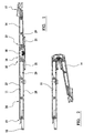
- FIGS. 1 and 2 of the drawings are side views of the overall length of a two part endless conveyor according to the invention, designated generally by reference 10, and which may take the form of a tail conveyor intended to be mounted on the frame (not shown) of a material treatment apparatus, such as a mobile or transportable screening and/or crushing plant.
- a material treatment apparatus such as a mobile or transportable screening and/or crushing plant.
- the conveyor 10 has a first conveyor part 11, which is the "head part”, and which has a pivotable mounting 12 at a first end 13 of the conveyor part 11, by means of which the entire conveyor 10 can be pivotally mounted on the frame of the apparatus.
- a second conveyor part 14, comprising the tail part, is adjustably mounted at a first end 15 on an opposite second end 16 of the first conveyor part 11.
- the conveyor parts 11 and 14 are relatively adjustable between an in-line operative or deployed position, as shown in Figure 1, and a folded transport position shown in Figure 2. In the operative position, the second conveyor part 14 forms a prolongation of the first conveyor part 11, and the opposite second end 17 of the second conveyor part 14 forms the discharge end of the overall conveyor 10.
- the second conveyor part 14 Underlies the first conveyor part 11, and extends generally parallel thereto, so that the folded conveyor 10 has reduced overall length, and also takes up a relatively small space in the folded position, which is particularly suitable when mounting the conveyor 10 below a screen box of a mobile screening plant.
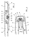
- Figures 1 and 2 show the overall length of the conveyor 10, and Figures 3 and 4 are corresponding illustrations, to an enlarged scale, showing the folding mechanism interconnecting the adjacent ends 15 and 16 of the conveyor parts 14 and 11.
- the folding mechanism is designated generally by reference 18, and comprises a coupling block or linkage 19 which interconnects the second end 16 of the first conveyor part 11 and the first end 15 of the second conveyor part 14 via respective ones of a pair of pivots 20.
- the mechanism 18 also includes a pair of linear actuators 21, each associated with a respective one of the conveyor parts 11, 14, and extending between mounting points 22 on the conveyor parts 11 and 14, and pivot connections 23 to the coupling block 19.
- Each actuator 21, preferably taking the form of a piston cylinder device (though other linear actuators may be used) is operative to rotate the coupling block 19 through approximately 90° about the respective pivot 20, and therefore a combined relative rotation between the conveyor parts 11 and 14 of approximately 180° can be achieved, for movement between the deployed position, and the transport position.
- Removable locking pins 24 are provided, to maintain the conveyor parts 11 and 14 in the deployed position, and levelling bolts 25 are mounted on the coupling block 19, and engagable with the locking pins 24. Adjustment of the levelling bolts 25 permit fine adjustment in the relative inclination between the conveyor parts 11 and 14, when in the deployed position.
- the endless conveyor 10 includes an endless conveyor belt 26 having an upper run 27 and a lower run 28, and guide rollers are mounted on the frames of the conveyor parts 11 and 14, to guide the movement of the endless belt 26 on an endless path.
- Guide rollers 29 are shown guiding the movement of the lower run 28.
- a roller 30 is mounted on the coupling block 19, and serves to guide the lower run 28 of the endless conveyor belt 26, and seeks to maintain tension in the lower run, (during movement between the operative position and the transport position), or at least guidance for the endless belt 26 when in the transport position, thereby avoiding, or at least minimising the formation of slack portion of belt, which might otherwise hang downwardly from the endless conveyor.
- the illustrated embodiment provides a very satisfactory folding mechanism between two adjacent ends of a folding conveyor, and without generation of slack portions of belt falling downwardly under gravity during movement to the transport position, and it is believed that this technical advantage arises directly out of the design parameters of the folding mechanism.
- the pivots 20 are located substantially mid height of the respective conveyor parts i.e. approximately midway between the upper and lower belt runs, and this has a favourable influence on the force which is applied to the endless belt during the folding and unfolding process.
- the provision of the roller 30 also has a favourable influence on the control of tension, and guidance of the lower run of the conveyor belt, during both folding, and unfolding movement.
- the roller 30, which may be considered to be a return roller, is located internally on the linkage centre line.
- the means disclosed to permit underfolding, as applied to a "tail conveyor" provides a length advantage i.e. reduction of about 0.5 metres, which is a significant factor in complying with traffic regulations.
Landscapes
- Engineering & Computer Science (AREA)
- Mechanical Engineering (AREA)
- Folding Of Thin Sheet-Like Materials, Special Discharging Devices, And Others (AREA)
- Framework For Endless Conveyors (AREA)
- Auxiliary Devices For And Details Of Packaging Control (AREA)
- Structure Of Belt Conveyors (AREA)
Claims (10)
- Zweiteiliges endloses Fördermittel (10), welches zwischen einer ausgerichteten betriebsbereiten Stellung und einer gefalteten Transportstellung einstellbar ist und welches umfasst: ein erstes Förderteil (11), welches derart ausgestaltet ist, dass es an einem ersten Ende (13) an dem Rahmen einer Materialbearbeitungsvorrichtung angebracht ist; ein zweites Förderteil (14), welches einstellbar an einem ersten Ende (15) an einem gegenüberliegenden zweiten Ende (16) des ersten Förderteils (11) für eine Bewegung zwischen einer betriebsbereiten Stellung, in welcher das zweite Förderteil (14) eine Verlängerung des ersten Förderteils (11) ausbildet, so dass das gegenüberliegende zweite Ende (17) des zweiten Förderteils (14) ein Entladeende des Fördermittels (10) ausbildet, und einer Transportstellung, in welcher eins der Förderteile (11,14) unter dem anderen Förderteil liegt und sich im Wesentlichen parallel dazu erstreckt, angebracht ist; und ein Faltmechanismus (18), welcher das zweite Ende (16) des ersten Förderteils (11) mit dem ersten Ende (15) des zweiten Förderteils (14) verbindet:
dadurch gekennzeichnet, dass der Faltmechanismus umfasst:einen Kupplungsblock oder eine Verbindung (19), welche das zweite Ende (16) des ersten Förderteils (11) und das erste Ende (15) des zweiten Förderteils (14) über einen entsprechenden eines Paares von Zapfen (20) verbindet, wobei sich die Achsen der Zapfen in einem Abstand voneinander befinden; undein Paar von linearen Betätigungsvorrichtungen (21), wobei jede einem entsprechenden Förderteil (11,14) zugeordnet ist und sich zwischen einem Montagepunkt (22) auf dem Förderteil und einer Verbindung (23) zu dem Kupplungsblock (19) erstreckt, wobei jede Betätigungsvorrichtung betriebsfähig ist, um den Kupplungsblock (19) um ungefähr 90° um den entsprechenden Zapfen (20) zu drehen, wobei der Faltmechanismus (18) unter der Tätigkeit der zwei linearen Betätigungsvorrichtungen (21) die Förderteile (11,14) zwischen der ausgerichteten betriebsfähigen Stellung und der gefalteten Transportstellung einstellen kann. - Fördermittel nach Anspruch 1, welches die Form eines Endfördermittels zur Montage auf dem Rahmen einer Materialbearbeitungsvorrichtung annimmt, wobei das erste Förderteil (11) ein Kopfstück ist, welches derart ausgestaltet ist, dass es auf dem Rahmen der Vorrichtung zu montieren ist, und wobei das zweite Förderteil (14) ein Endteil des Fördermittels ist.
- Fördermittel nach Anspruch 2, wobei das Fördermittel um ein Montageteil (12) an dem ersten Ende (13) des Kopfteils (11) einstellbar ist, um die Neigung des Fördermittels zu verändern, wenn es sich in der betriebsfähigen Stellung befindet.
- Fördermittel nach einem der vorhergehenden Ansprüche, welches eine Führungsanordnung (30) aufweist, welche in dem Faltmechanismus (18) angebracht ist und betriebsfähig ist, um den unteren Lauf (28) eines Endlosbandes (26), welches sich entlang einer endlosen Bahn um die Förderteile (11, 14) herum erstreckt, zu führen, wobei die Führungsanordnung derart betriebsfähig ist, dass sie dem unteren Lauf (28) des Endlosbandes (26) während einer relativen Bewegung der Förderteile (11,14) zwischen der betriebsfähigen Stellung und der Transportstellung einen Zug verleiht.
- Fördermittel nach Anspruch 4, wobei die Führungsanordnung eine Walze (30) umfasst, welche auf dem Kupplungsblock oder der Verbindung (19) für eine Bewegung damit angebracht ist.
- Fördermittel nach Anspruch 5, wobei die Walze (30) innerhalb auf der Mittellinie des Kupplungsblocks oder der Verbindung (19) angebracht ist.
- Fördermittel nach einem der vorhergehenden Ansprüche, wobei jede lineare Betätigungsvorrichtung (21) eine Kolben-/Zylindervorrichtung umfasst.
- Fördermittel nach Anspruch 7, wobei die Kolben-/Zylindervorrichtungen (21) hydraulisch betätigbar sind.
- Fördermittel nach Anspruch 8, wobei die Kolben-/Zylindervorrichtungen (21) unabhängig oder gleichzeitig betätigbar sind.
- Materialbearbeitungsvorrichtung, welche ein Fördermittel nach einem der Ansprüche 1 bis 9 aufweist, welches darauf angebracht ist.
Applications Claiming Priority (3)
| Application Number | Priority Date | Filing Date | Title |
|---|---|---|---|
| GB0027129 | 2000-11-04 | ||
| GBGB0027129.6A GB0027129D0 (en) | 2000-11-04 | 2000-11-04 | Folding mechanism for a two part endless conveyor |
| PCT/GB2001/004857 WO2002036461A1 (en) | 2000-11-04 | 2001-11-01 | Folding mechanism for a two part endless conveyor |
Publications (2)
| Publication Number | Publication Date |
|---|---|
| EP1334053A1 EP1334053A1 (de) | 2003-08-13 |
| EP1334053B1 true EP1334053B1 (de) | 2006-03-08 |
Family
ID=9902672
Family Applications (1)
| Application Number | Title | Priority Date | Filing Date |
|---|---|---|---|
| EP01980684A Expired - Lifetime EP1334053B1 (de) | 2000-11-04 | 2001-11-01 | Faltmechanismus für einen zweiteiligen endlosförderer |
Country Status (8)
| Country | Link |
|---|---|
| US (1) | US6708814B2 (de) |
| EP (1) | EP1334053B1 (de) |
| AT (1) | ATE319636T1 (de) |
| AU (1) | AU2002212477A1 (de) |
| DE (1) | DE60117838T2 (de) |
| ES (1) | ES2261493T3 (de) |
| GB (1) | GB0027129D0 (de) |
| WO (1) | WO2002036461A1 (de) |
Families Citing this family (28)
| Publication number | Priority date | Publication date | Assignee | Title |
|---|---|---|---|---|
| US7337895B2 (en) * | 2003-04-08 | 2008-03-04 | Marc De Maeyer | Mobile gastronomic table for serving out food |
| US7177391B2 (en) * | 2005-03-29 | 2007-02-13 | Surescan Corporation | Imaging inspection apparatus |
| US7261466B2 (en) * | 2005-06-01 | 2007-08-28 | Endicott Interconnect Technologies, Inc. | Imaging inspection apparatus with directional cooling |
| US7354197B2 (en) * | 2005-06-01 | 2008-04-08 | Endicott Interconnect Technologies, Inc. | Imaging inspection apparatus with improved cooling |
| US20070264111A1 (en) * | 2006-05-10 | 2007-11-15 | Diana Cooper | System for loading, unloading and transporting cargo |
| US20070267273A1 (en) * | 2006-05-22 | 2007-11-22 | Walsh Joseph M | Foldable conveyor with automatic tensioning device |
| US7347311B2 (en) * | 2006-06-07 | 2008-03-25 | Volvo Construction Equipment Ab | Folding mechanism for road machinery foldable conveyors |
| US8162245B2 (en) | 2006-06-22 | 2012-04-24 | Terex Usa, Llc | Mobile aggregate crushing system and method |
| US7261200B1 (en) | 2007-01-08 | 2007-08-28 | Spudnik Equipment Company, Llc | Assembly for moving and rotating conveyor |
| US8104607B2 (en) * | 2007-09-28 | 2012-01-31 | American Highwall Systems, Inc. | Connection arrangements for mine conveyor sections |
| US20100008750A1 (en) * | 2008-07-08 | 2010-01-14 | Dan Jones, Inc. | Trailers,systems and methods for transferring material |
| GB0905003D0 (en) * | 2009-03-24 | 2009-05-06 | Powerscreen Int Distribution | Foldable and extendible conveyor |
| US8833539B2 (en) * | 2010-09-13 | 2014-09-16 | Superior Industries, Inc. | Portable belt conveyor system |
| AU2011100919B4 (en) * | 2011-07-27 | 2013-02-14 | Barrett-Lennard, Matthew Douglas Mr | Two Position Conveyor |
| RU2634918C2 (ru) * | 2013-09-04 | 2017-11-08 | Метсо Минерэлз, Инк. | Установка по переработке минеральных материалов и способ управления такой установкой |
| CN107651381B (zh) * | 2017-10-16 | 2019-12-13 | 安徽芜湖宝丰输送机械有限公司 | 一种中部呈拱形的皮带传输装置 |
| CA3112137C (en) * | 2018-10-22 | 2021-08-10 | Walmart Apollo, Llc | Folding wing for a conveyor |
| MX2021007029A (es) * | 2018-12-13 | 2021-08-11 | Cornerstone Automation Systems Llc | Desplazador de productos abatible. |
| CA3138680C (en) * | 2019-04-30 | 2025-03-25 | Quickthree Technology, Llc | MULTI-ACTUATOR ROTATOR ASSEMBLY |
| CN114787039A (zh) | 2019-09-05 | 2022-07-22 | 高效科技股份有限公司 | 自主行李设备 |
| US11014753B1 (en) | 2019-11-07 | 2021-05-25 | Caterpillar Paving Products Inc. | Trajectory control of discharge conveyor |
| US11554919B2 (en) * | 2020-02-26 | 2023-01-17 | Intelligrated Headquarters, Llc | Lift gate apparatus |
| FI129693B (en) | 2021-06-17 | 2022-06-30 | Metso Outotec Finland Oy | Arrangement, system and method for supporting an adjustable conveyor of a mobile mineral material handling station |
| CN113955401B (zh) * | 2021-11-12 | 2023-07-04 | 博众精工科技股份有限公司 | 一种在线处理装置 |
| CN114104596A (zh) * | 2021-12-17 | 2022-03-01 | 上海山容塑料科技有限公司 | 一种车辆后备厢内置的货物装卸折叠架 |
| CN116588582A (zh) * | 2023-06-19 | 2023-08-15 | 珠海博杰电子股份有限公司 | 一种自动化折叠流水线 |
| US20250229991A1 (en) * | 2024-01-12 | 2025-07-17 | Rocky Mountain Investor Holdings, Inc. | Conveyor with Directional Fold |
| DE102024103593A1 (de) * | 2024-02-08 | 2025-08-14 | Kleemann Gmbh | Mobiles Haldenband |
Family Cites Families (6)
| Publication number | Priority date | Publication date | Assignee | Title |
|---|---|---|---|---|
| US3599784A (en) * | 1968-12-16 | 1971-08-17 | Lionello Rossi | Automotive continuous conveyor of an articulated type |
| US3616893A (en) * | 1969-04-03 | 1971-11-02 | Athey Products Corp | Mobile hydraulically foldable conveyor |
| US4427104A (en) | 1981-07-14 | 1984-01-24 | Reid Bros., Inc. | Radial stacker |
| CA1261303A (en) * | 1987-10-21 | 1989-09-26 | Stephen L. Foster | Extendable boom for belt conveyor |
| US5443351A (en) * | 1992-02-28 | 1995-08-22 | Pettijohn; Michael J. | Mobile hydraulic conveyor |
| US6129196A (en) * | 1998-07-27 | 2000-10-10 | Lapper; Derek | Counterbalanced mono-fold stockpiling trailer conveyor |
-
2000
- 2000-11-04 GB GBGB0027129.6A patent/GB0027129D0/en not_active Ceased
-
2001
- 2001-11-01 AT AT01980684T patent/ATE319636T1/de not_active IP Right Cessation
- 2001-11-01 AU AU2002212477A patent/AU2002212477A1/en not_active Abandoned
- 2001-11-01 DE DE60117838T patent/DE60117838T2/de not_active Expired - Lifetime
- 2001-11-01 EP EP01980684A patent/EP1334053B1/de not_active Expired - Lifetime
- 2001-11-01 US US10/169,597 patent/US6708814B2/en not_active Expired - Lifetime
- 2001-11-01 ES ES01980684T patent/ES2261493T3/es not_active Expired - Lifetime
- 2001-11-01 WO PCT/GB2001/004857 patent/WO2002036461A1/en not_active Ceased
Also Published As
| Publication number | Publication date |
|---|---|
| US6708814B2 (en) | 2004-03-23 |
| AU2002212477A1 (en) | 2002-05-15 |
| ES2261493T3 (es) | 2006-11-16 |
| GB0027129D0 (en) | 2000-12-20 |
| DE60117838D1 (de) | 2006-05-04 |
| ATE319636T1 (de) | 2006-03-15 |
| US20030121761A1 (en) | 2003-07-03 |
| EP1334053A1 (de) | 2003-08-13 |
| DE60117838T2 (de) | 2006-12-07 |
| WO2002036461A1 (en) | 2002-05-10 |
Similar Documents
| Publication | Publication Date | Title |
|---|---|---|
| EP1334053B1 (de) | Faltmechanismus für einen zweiteiligen endlosförderer | |
| CA2680081C (en) | Foldable framework for auxiliary conveyor | |
| US6705449B2 (en) | Bulk material processing apparatus | |
| US6186338B1 (en) | Self-propelled material-processing apparatus | |
| AU2013399879B2 (en) | A mineral material processing plant and a method for operating a processing plant | |
| JP6234587B2 (ja) | 鉱物材料処理設備および処理設備の稼働方法 | |
| EP1360127B1 (de) | Vertikalumlenkeinrichtung | |
| JP6236161B2 (ja) | 鉱物材料処理設備および処理設備の稼働方法 | |
| US11339004B2 (en) | Movable material processing apparatus comprising a foldable conveyor | |
| US7264104B2 (en) | Crusher in-feed conveyor method and apparatus | |
| US4011936A (en) | Conveyor positioning structure for loading and conveying machines | |
| JP2016530094A (ja) | 鉱物原料の処理プラント、及び、処理プラントの運転方法 | |
| US20020005140A1 (en) | Machine for removing an old track and laying a new track | |
| US3557937A (en) | Tensioning apparatus for an endless conveyor | |
| CN114313774B (zh) | 材料加工装置 | |
| JPH09511433A (ja) | ふるい分け装置 | |
| NO853186L (no) | Anordning for styring av transportoerbaand. | |
| JP3223356B2 (ja) | トンネル掘削用のテール装置 | |
| US5950540A (en) | Swingable conveyor device for printing units | |
| JP2809598B2 (ja) | 移動式搬送体処理設備用のベルトコンベア装置 | |
| GB2640436A (en) | Folding conveyor | |
| JPH082647A (ja) | 急傾斜コンベヤ設備 | |
| KR980001774A (ko) | 골재하역 컨베이어장치 | |
| JPS6155014A (ja) | 採鉱作業において用いるようなコンベアシステムに用いるベルト案内装置 | |
| SE8102468L (sv) | Avlastningsanordning for en transportor |
Legal Events
| Date | Code | Title | Description |
|---|---|---|---|
| PUAI | Public reference made under article 153(3) epc to a published international application that has entered the european phase |
Free format text: ORIGINAL CODE: 0009012 |
|
| 17P | Request for examination filed |
Effective date: 20020701 |
|
| AK | Designated contracting states |
Designated state(s): AT BE CH CY DE DK ES FI FR GB GR IE IT LI LU MC NL PT SE TR |
|
| AX | Request for extension of the european patent |
Extension state: AL LT LV MK RO SI |
|
| 17Q | First examination report despatched |
Effective date: 20040224 |
|
| GRAP | Despatch of communication of intention to grant a patent |
Free format text: ORIGINAL CODE: EPIDOSNIGR1 |
|
| RIN1 | Information on inventor provided before grant (corrected) |
Inventor name: WAGSTAFFE, CHRISTOPHER WILLIAM |
|
| RAP1 | Party data changed (applicant data changed or rights of an application transferred) |
Owner name: EXTEC SCREENS AND CRUSHERS LIMITED |
|
| GRAS | Grant fee paid |
Free format text: ORIGINAL CODE: EPIDOSNIGR3 |
|
| GRAA | (expected) grant |
Free format text: ORIGINAL CODE: 0009210 |
|
| AK | Designated contracting states |
Kind code of ref document: B1 Designated state(s): AT BE CH CY DE DK ES FI FR GB GR IE IT LI LU MC NL PT SE TR |
|
| PG25 | Lapsed in a contracting state [announced via postgrant information from national office to epo] |
Ref country code: NL Free format text: LAPSE BECAUSE OF FAILURE TO SUBMIT A TRANSLATION OF THE DESCRIPTION OR TO PAY THE FEE WITHIN THE PRESCRIBED TIME-LIMIT Effective date: 20060308 Ref country code: LI Free format text: LAPSE BECAUSE OF FAILURE TO SUBMIT A TRANSLATION OF THE DESCRIPTION OR TO PAY THE FEE WITHIN THE PRESCRIBED TIME-LIMIT Effective date: 20060308 Ref country code: IT Free format text: LAPSE BECAUSE OF FAILURE TO SUBMIT A TRANSLATION OF THE DESCRIPTION OR TO PAY THE FEE WITHIN THE PRESCRIBED TIME-LIMIT;WARNING: LAPSES OF ITALIAN PATENTS WITH EFFECTIVE DATE BEFORE 2007 MAY HAVE OCCURRED AT ANY TIME BEFORE 2007. THE CORRECT EFFECTIVE DATE MAY BE DIFFERENT FROM THE ONE RECORDED. Effective date: 20060308 Ref country code: FI Free format text: LAPSE BECAUSE OF FAILURE TO SUBMIT A TRANSLATION OF THE DESCRIPTION OR TO PAY THE FEE WITHIN THE PRESCRIBED TIME-LIMIT Effective date: 20060308 Ref country code: CH Free format text: LAPSE BECAUSE OF FAILURE TO SUBMIT A TRANSLATION OF THE DESCRIPTION OR TO PAY THE FEE WITHIN THE PRESCRIBED TIME-LIMIT Effective date: 20060308 Ref country code: AT Free format text: LAPSE BECAUSE OF FAILURE TO SUBMIT A TRANSLATION OF THE DESCRIPTION OR TO PAY THE FEE WITHIN THE PRESCRIBED TIME-LIMIT Effective date: 20060308 Ref country code: BE Free format text: LAPSE BECAUSE OF FAILURE TO SUBMIT A TRANSLATION OF THE DESCRIPTION OR TO PAY THE FEE WITHIN THE PRESCRIBED TIME-LIMIT Effective date: 20060308 |
|
| REG | Reference to a national code |
Ref country code: GB Ref legal event code: FG4D |
|
| REG | Reference to a national code |
Ref country code: CH Ref legal event code: EP |
|
| REG | Reference to a national code |
Ref country code: IE Ref legal event code: FG4D |
|
| REF | Corresponds to: |
Ref document number: 60117838 Country of ref document: DE Date of ref document: 20060504 Kind code of ref document: P |
|
| PG25 | Lapsed in a contracting state [announced via postgrant information from national office to epo] |
Ref country code: DK Free format text: LAPSE BECAUSE OF FAILURE TO SUBMIT A TRANSLATION OF THE DESCRIPTION OR TO PAY THE FEE WITHIN THE PRESCRIBED TIME-LIMIT Effective date: 20060608 Ref country code: SE Free format text: LAPSE BECAUSE OF FAILURE TO SUBMIT A TRANSLATION OF THE DESCRIPTION OR TO PAY THE FEE WITHIN THE PRESCRIBED TIME-LIMIT Effective date: 20060608 |
|
| PG25 | Lapsed in a contracting state [announced via postgrant information from national office to epo] |
Ref country code: PT Free format text: LAPSE BECAUSE OF FAILURE TO SUBMIT A TRANSLATION OF THE DESCRIPTION OR TO PAY THE FEE WITHIN THE PRESCRIBED TIME-LIMIT Effective date: 20060808 |
|
| NLV1 | Nl: lapsed or annulled due to failure to fulfill the requirements of art. 29p and 29m of the patents act | ||
| REG | Reference to a national code |
Ref country code: CH Ref legal event code: PL |
|
| ET | Fr: translation filed | ||
| REG | Reference to a national code |
Ref country code: ES Ref legal event code: FG2A Ref document number: 2261493 Country of ref document: ES Kind code of ref document: T3 |
|
| PG25 | Lapsed in a contracting state [announced via postgrant information from national office to epo] |
Ref country code: MC Free format text: LAPSE BECAUSE OF NON-PAYMENT OF DUE FEES Effective date: 20061130 |
|
| PLBE | No opposition filed within time limit |
Free format text: ORIGINAL CODE: 0009261 |
|
| STAA | Information on the status of an ep patent application or granted ep patent |
Free format text: STATUS: NO OPPOSITION FILED WITHIN TIME LIMIT |
|
| 26N | No opposition filed |
Effective date: 20061211 |
|
| PG25 | Lapsed in a contracting state [announced via postgrant information from national office to epo] |
Ref country code: GR Free format text: LAPSE BECAUSE OF FAILURE TO SUBMIT A TRANSLATION OF THE DESCRIPTION OR TO PAY THE FEE WITHIN THE PRESCRIBED TIME-LIMIT Effective date: 20060609 |
|
| PG25 | Lapsed in a contracting state [announced via postgrant information from national office to epo] |
Ref country code: LU Free format text: LAPSE BECAUSE OF NON-PAYMENT OF DUE FEES Effective date: 20061101 Ref country code: TR Free format text: LAPSE BECAUSE OF FAILURE TO SUBMIT A TRANSLATION OF THE DESCRIPTION OR TO PAY THE FEE WITHIN THE PRESCRIBED TIME-LIMIT Effective date: 20060308 |
|
| PG25 | Lapsed in a contracting state [announced via postgrant information from national office to epo] |
Ref country code: CY Free format text: LAPSE BECAUSE OF FAILURE TO SUBMIT A TRANSLATION OF THE DESCRIPTION OR TO PAY THE FEE WITHIN THE PRESCRIBED TIME-LIMIT Effective date: 20060308 |
|
| REG | Reference to a national code |
Ref country code: FR Ref legal event code: PLFP Year of fee payment: 15 |
|
| REG | Reference to a national code |
Ref country code: FR Ref legal event code: PLFP Year of fee payment: 16 |
|
| PGFP | Annual fee paid to national office [announced via postgrant information from national office to epo] |
Ref country code: FR Payment date: 20161118 Year of fee payment: 16 |
|
| PGFP | Annual fee paid to national office [announced via postgrant information from national office to epo] |
Ref country code: ES Payment date: 20161114 Year of fee payment: 16 |
|
| PGFP | Annual fee paid to national office [announced via postgrant information from national office to epo] |
Ref country code: DE Payment date: 20171129 Year of fee payment: 17 |
|
| PGFP | Annual fee paid to national office [announced via postgrant information from national office to epo] |
Ref country code: IT Payment date: 20171130 Year of fee payment: 17 Ref country code: IE Payment date: 20171129 Year of fee payment: 17 |
|
| REG | Reference to a national code |
Ref country code: FR Ref legal event code: ST Effective date: 20180731 |
|
| PG25 | Lapsed in a contracting state [announced via postgrant information from national office to epo] |
Ref country code: FR Free format text: LAPSE BECAUSE OF NON-PAYMENT OF DUE FEES Effective date: 20171130 |
|
| REG | Reference to a national code |
Ref country code: ES Ref legal event code: FD2A Effective date: 20181221 |
|
| PG25 | Lapsed in a contracting state [announced via postgrant information from national office to epo] |
Ref country code: ES Free format text: LAPSE BECAUSE OF NON-PAYMENT OF DUE FEES Effective date: 20171102 |
|
| REG | Reference to a national code |
Ref country code: DE Ref legal event code: R119 Ref document number: 60117838 Country of ref document: DE |
|
| REG | Reference to a national code |
Ref country code: IE Ref legal event code: MM4A |
|
| PG25 | Lapsed in a contracting state [announced via postgrant information from national office to epo] |
Ref country code: DE Free format text: LAPSE BECAUSE OF NON-PAYMENT OF DUE FEES Effective date: 20190601 Ref country code: IE Free format text: LAPSE BECAUSE OF NON-PAYMENT OF DUE FEES Effective date: 20181101 Ref country code: IT Free format text: LAPSE BECAUSE OF NON-PAYMENT OF DUE FEES Effective date: 20181101 |
|
| PGFP | Annual fee paid to national office [announced via postgrant information from national office to epo] |
Ref country code: GB Payment date: 20201106 Year of fee payment: 20 |
|
| REG | Reference to a national code |
Ref country code: GB Ref legal event code: PE20 Expiry date: 20211031 |
|
| PG25 | Lapsed in a contracting state [announced via postgrant information from national office to epo] |
Ref country code: GB Free format text: LAPSE BECAUSE OF EXPIRATION OF PROTECTION Effective date: 20211031 |