EP1327400B1 - Sitz-/Liegemöbel - Google Patents
Sitz-/Liegemöbel Download PDFInfo
- Publication number
- EP1327400B1 EP1327400B1 EP02027865.1A EP02027865A EP1327400B1 EP 1327400 B1 EP1327400 B1 EP 1327400B1 EP 02027865 A EP02027865 A EP 02027865A EP 1327400 B1 EP1327400 B1 EP 1327400B1
- Authority
- EP
- European Patent Office
- Prior art keywords
- seat part
- back part
- section
- furniture
- seat
- Prior art date
- Legal status (The legal status is an assumption and is not a legal conclusion. Google has not performed a legal analysis and makes no representation as to the accuracy of the status listed.)
- Expired - Lifetime
Links
- 238000005452 bending Methods 0.000 description 27
- 238000004873 anchoring Methods 0.000 description 4
- 230000001419 dependent effect Effects 0.000 description 4
- 230000000694 effects Effects 0.000 description 3
- 239000002184 metal Substances 0.000 description 3
- 230000008878 coupling Effects 0.000 description 2
- 238000010168 coupling process Methods 0.000 description 2
- 238000005859 coupling reaction Methods 0.000 description 2
- 239000002023 wood Substances 0.000 description 2
- 238000010276 construction Methods 0.000 description 1
- 230000003993 interaction Effects 0.000 description 1
- 239000000463 material Substances 0.000 description 1
- 230000002787 reinforcement Effects 0.000 description 1
- 238000005096 rolling process Methods 0.000 description 1
Images


Classifications
-
- A—HUMAN NECESSITIES
- A47—FURNITURE; DOMESTIC ARTICLES OR APPLIANCES; COFFEE MILLS; SPICE MILLS; SUCTION CLEANERS IN GENERAL
- A47C—CHAIRS; SOFAS; BEDS
- A47C1/00—Chairs adapted for special purposes
- A47C1/02—Reclining or easy chairs
- A47C1/031—Reclining or easy chairs having coupled concurrently adjustable supporting parts
- A47C1/032—Reclining or easy chairs having coupled concurrently adjustable supporting parts the parts being movably-coupled seat and back-rest
-
- A—HUMAN NECESSITIES
- A47—FURNITURE; DOMESTIC ARTICLES OR APPLIANCES; COFFEE MILLS; SPICE MILLS; SUCTION CLEANERS IN GENERAL
- A47C—CHAIRS; SOFAS; BEDS
- A47C1/00—Chairs adapted for special purposes
- A47C1/02—Reclining or easy chairs
- A47C1/031—Reclining or easy chairs having coupled concurrently adjustable supporting parts
- A47C1/036—Reclining or easy chairs having coupled concurrently adjustable supporting parts the parts including a head-rest
Definitions
- the invention relates to a sitting / lying furniture according to the preamble of claim 1.
- EP-A-0 721 751 discloses a recliner with a base carrying a chair frame with two armrests. At the rear end of the armrests an adjustable to a chair seat backrest is articulated. Between the chair frame and the armrests slide rails, along which the armchair seat is guided, when the backrest is adjusted. By a locking mechanism, the chair seat can be locked to the slide rails.
- the object of the invention is to provide a sitting / reclining furniture of the type mentioned in such a way that previously unrealized embodiments of the furniture are made possible, in particular, should also arise in terms of design new possibilities and also should be ensured that for a user the highest possible seating / lying comfort is given.
- the seat part and the back bearing cantilever support structure which has at least one support bracket having a base portion, an at least approximately horizontal horizontal portion and a base portion and the horizontal portion connecting with each other and a pivoting of the horizontal portion relative to the base portion enabling the hinge portion comprises, wherein the back part supported about a horizontal axis pivotally mounted on the horizontal portion and the seat portion is forcibly guided along the hinge portion.
- a cantilever furniture is created, so a piece of furniture in which the user can cause a pivoting or swinging of the seat by simple weight transfer, the cantilever furniture according to the invention allows adjusting the inclination of the back part in a manner that does not require additional supports of the seat part or the back part, since according to the invention the back part and the seat part are supported on the mounting bracket of the cantilever support structure.
- the back portion urges the seat portion, which is then moved relative to the support bracket and moves along a predetermined path by the positive guidance along the hinge portion of the support bracket.
- the back and the seat part so change not only their relative position with each other, but also their position relative to the mounting bracket. Due to the free-running ability of the support bracket but now the configuration of the support bracket itself is variable, since the support bracket during pivoting or swinging of the horizontal section depending on the forces acting its shape changed more or less.
- the invention further creates new design possibilities and in particular allows lightweight and delicate-looking constructions, since no additional supports are required due to the inventive support of the unit of back and seat part on the mounting bracket.
- the seat part forcibly guided on the mounting bracket is pivotable about a horizontal axis relative to the mounting bracket, which runs in particular in the region of a positively guided guide portion of the seat part.
- the support bracket, the back part and the seat part viewed from the side form a closed, variable by adjusting the inclination of the back part in its shape hinge frame.
- the mounting bracket is open.
- the mounting bracket has at least approximately the shape of a lying on the side, in particular to the rear open U.
- the hinge portion of the support bracket has at least approximately an S-shape.
- the mounting bracket extends at least substantially in a vertical plane.
- the seat part and the back part between two parallel staggered mounting brackets are arranged.
- the back part is supported in the region of a free rear end of the horizontal section.
- the back part is preferably articulated in the region of its free lower end to the seat part.
- the back part is articulated with a curved, with the convex side facing forward portion of the seat part.
- the seat part is arranged offset with respect to the horizontal section downwards. Furthermore, it is preferred that the seat part is forcibly guided with an intermediate region on the joint section. Preferably, the seat part is articulated in the region of its free rear end to the back part.
- At least the positive guiding portion of the joint portion extends inclined in a further preferred embodiment of the invention with respect to the horizontal.
- the forced guidance region is preferably at least approximately straight. If according to another preferred Embodiment of the invention, the positive guide portion is curved, then it is preferred if the positive guide portion facing up with its concave side.
- the seat part is lockable on the hinge portion.
- the seat part is preferably a particular lever-operated parking brake provided.
- the positive guide comprises a guide rail integrated in the joint section and a sliding saddle connected to the seat part and forcibly guided on the guide rail.
- At least one brake pad is held loosely between the sliding calliper and the guide rail, which can be pressed against the guide rail by means of an actuating member mounted on the sliding calliper and designed in particular as a lever.
- the actuator may have an eccentric portion which is adjustable between a braking position acting on the brake pad and a release position.
- the seat / back unit is coupled with at least one actuator for at least one additional device such that a Ne Trentsverstelliolo the back part relative to the seat part automatically by means of the actuator in an adjustment of the additional device can be implemented.
- the tilt adjustment movement of the back part is used to adjust the additional device by means of the actuator. In this way, the seating or lying conditions for the user are automatically changed with regard to the additional device when the inclination of the back part is adjusted.
- the tilting movement of the back part of the actuating member is movable relative to the back part.
- the attachment is preferably a pivotally attached to the back part, also referred to as neck support head part or held on the back, also known as lumbar support lumbar support.
- a head part and a lumbar support can be adjustable at the same time by means of an actuating member.
- the attachment is attached to the back and coupled via the actuator to the seat part.
- the additional device and the actuator are not exclusively connected to the back part, but for the movement of the actuator for adjusting the additional device plays the way the relative movement between the back and the seat part when adjusting the inclination of the back part a role.
- actuating member is articulated to the seat part.
- the actuating member comprises a linkage, which is in particular formed by at least one actuating rod extending substantially parallel to the back part.
- the actuator interacts indirectly via a further adjusting device with the additional device.
- the further adjusting device may be a Bowden cable arrangement.
- It may be coupled with a designed as a lumbar support attachment via a Bowden cable arrangement, the actuator. It can be exercised when the upright of the back part of the Bowden cable arrangement on the lumbar support train.
- the lumbar support comprises a bending plate with dependent on the inclination of the back part, variable by means of the actuator curvature, preferably wherein the curvature of the bending plate in upright back part maximum and at maximum inclined back part minimal, preferably at least substantially zero.
- the bending plate extends at maximum inclined back part parallel to the back part or to the back surface, wherein the bending plate can be slightly curved in accordance with the curvature of the back part. In this way, the lumbar support for the user is practically not noticeable when the back part pivots all the way down, that is maximally inclined.
- the bending plate is bendable against a restoring force, in particular caused by inherent elasticity, by means of the actuating member.
- a traction element of the Bowden cable arrangement starting from its anchorage at the upper or lower first end of the bending plate along the back of the bending plate to the opposite second end of the bending plate and further via a stop fixed to the back part up to its anchoring to the actuator extends, wherein the length of the tension member between the second end of the bending plate and the stopper is kept constant regardless of the inclination of the back part.
- a traction element of the Bowden cable arrangement is at least substantially in a direction parallel to the back plane extending.
- a pulling member of the Bowden cable arrangement is laid approximately in the form of an upwardly open U.
- the attachment comprises a head part pivotally mounted on the back, it is preferably provided that the actuating member is articulated with its one end to the head part and with its other end to the seat part.
- the actuating member is effective with respect to the head part in Aufrechtstellen the back part as a thrust member and the pivoting of the back part down as a pulling member.
- a bias exerted by the actuator on the auxiliary device can be changed.
- the actuating member comprises a traction cable arrangement, which is attached at one end to the seat part and at the other end to the attachment. It is preferably provided that the additional device can be acted upon by the tensioning cable arrangement with an adjustable biasing force, in particular by means of a spring device with adjustable prestressing connected in addition to a tensioning cable between the auxiliary device and the seat part.
- a traction cable of the traction cable arrangement starting from the underside of the seat part, is first guided on the underside of the seat part and then on the rear side of the back part up to the additional device, in particular attached to the back part.
- the lumbar support designed in particular as a bending plate is articulated in the region of its upper end to the back part and can be pivoted about a horizontal axis by means of the actuating member, in particular a pull cable arrangement.
- the actuating member in particular a Switzerlandseilan extract, is coupled to the lumbar support via a lever arrangement.
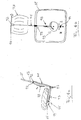
- the Fig. 1a and 1b is shown without upholstery, it is a chair with tilt-adjustable back part 13, which is also referred to below as the backrest.
- the backrest 13 is pivotally connected to a seat part 11 and pivotable about a pivot axis 35 relative to the seat part 11.
- the backrest 13 is connected to a headrest 29, also referred to as a neck support, which is pivotable about an axis 31 relative to the backrest 13, wherein the position of the head portion 29 with respect to the backrest 13 of the inclination of the backrest 13 with respect to the seat part 11 dependent is.
- the head part 29 is adjusted by means of an actuating rod 41, which is articulated with its one end to the head part 29 and with its opposite end to the seat part 11. Further is by means of the actuating rod 41 which is dependent on the inclination of the backrest 13 position of a held on the backrest 13 lumbar support 33 changed.
- the seat / reclining furniture according to the invention further comprises a cantilever support structure comprising two parallel staggered, each extending in a vertical plane supporting bracket 15 which are connected to a base part 39.
- the support bracket 15 are preferably made of wood, but may also be made of a different material, such as a wood laminate, an additional metal reinforcement or exclusively made of metal.
- the mounting brackets 15 each have an approximately horizontally extending horizontal portion 19, a horizontally extending, connected to the base portion 39 base portion 17 and an approximately S-shaped hinge portion 21 which connects the horizontal portion 19 and the base portion 17 and with a comparatively short, Approximately vertically extending portion 43 merges into the base portion 17.
- the backrest 13 is supported with an intermediate region at the rear free ends of the horizontal sections 19 and pivotable about a horizontal axis 23 there.
- the seat part 11 is supported in each case with a downwardly projecting guide portion 37 on an obliquely upward, slightly curved and with its concave side of the horizontal portion 19 facing forced guide portion 27 of the hinge portion 21.
- the manner of restraint of the seat part 11 and the guide portions 37 on the support brackets 15 can basically be done in any manner, for example by rolling or sliding elements.
- the positive guide comprises integrated into the joint portions 21 and in particular made of metal guide rails, wherein the guide portions 37 of the seat part 11 are formed as the guide rails encompassing sliding saddles, each allow a translational movement of the seat part 11 relative to the support bracket 15 only along the predetermined path by the guide rail ,
- the seat part 11 is also pivotable about a horizontal, extending in the region of the guide portions 37 axis relative to the hinge portion 21.
- a respectively set inclination of the backrest 13 can be effected by fixing at least one guide section 37 on the respective joint section 21, for which purpose a lever-operated parking brake is provided.
- the parking brake comprises a brake pad which is held loosely between the sliding calliper and the guide rail and which can be pressed against the guide rail by turning an eccentric section mounted on an actuating lever and sliding on a sliding calliper from a release position into a braking position acting on the brake pad.
- the support bracket 15, the back part 13 and the seat part 11 each form a closed lateral hinge frame whose shape is changed by adjusting the inclination of the back part 13.
- this hinge frame In the position according to Fig. 1a with upright backrest 13, this hinge frame has approximately the shape of a rectangle with an enclosed surface 36, while in the position according to Fig. 1b having downwardly pivoted backrest 13 of the hinge frame approximately the shape of a triangle, wherein the triangular surface 36 'according to Fig. 1b smaller than the rectangular area 36 according to FIG Fig. 1a is because the seat part 11 has moved to the horizontal portion 19 to the top.
- This change in shape of the lateral hinge frame 36, 36 ' is caused by the inclination adjustment of the backrest 13, this main effect can be superimposed on a caused by the pivoting or swinging of the horizontal portions 19, to an additional change in shape of the hinge frame 36, 36' leading side effect, if appropriate Forces act on the seating / reclining furniture.
- the chair comprises a seat / back unit of a back part 13 and a seat part 11, which are hinged together, so that the back part 13 about a horizontal axis 35 relative to the seat part 11th can be pivoted.
- the back part 13 carries a head part 29, which is pivotable about a horizontal axis 31 relative to the back part 13.
- the back part 13 is provided with a lumbar support 33.
- the head part 29 and the lumbar support 33 are additional devices in the sense of the present application and can be adjusted by changing the inclination of the back part 13 relative to the seat part 11, which will be discussed in more detail below.
- the seat / back unit is provided with an actuating device, of two on the sides of the back part 13 and - like Fig. 4 and 5 show - substantially parallel to the side struts of a U-frame comprehensive back portion 13 extending actuating rods 41 is formed.
- the actuating rods 41 are articulated in each case with its lower free end to the seat part 11 in its rear region and connected with its upper free end articulated to the head part 29 at its lower region. In this way, the head part 29 is coupled via the actuating rods 41 to the seat part 11 in such a way that the actuating rods 41 are effective in each case as a thrust member or as a pulling member for the head part 29 as a function of the direction of their essentially parallel to their longitudinal extension.
- the seat / back unit is supported on a cantilever support structure comprising two parallel staggered mounting bracket 15, between which the seat / back unit is arranged and which are connected to a base part 39.
- the support brackets 15 are each provided in the form of a horizontal U and have a substantially horizontally extending, straight horizontal portion 19, a horizontally extending base portion 17 and an approximately S-shaped hinge portion 21 which connects the horizontal portion 19 and the base portion 17 with each other, a pivoting or swinging of the horizontal section 19 relative to the base section 17 is possible.
- the back part 13 is supported with an intermediate region at the free rear ends of the horizontal sections 19 and is pivotable there about a horizontal axis 23 relative to the support structure.
- the seat part 11 is provided at an intermediate portion with a downwardly projecting guide portion 37, which may be basically arbitrary and, for example, comprises one or more roller or sliding elements. With the guide sections 37, the seat part 11 is forcibly guided on the support brackets 15 such that the guide sections 37 can each move translationally only along a forced guide section 27 formed on the hinge section 21 of the respective support bracket 15.
- the seat part 11 is also pivotable about a horizontal, extending in the region of the guide portions 37 axis relative to the hinge portion 21.
- FIG. 2 The comparison of Fig. 2 and Fig. 3 shows that with upright back part according to Fig. 2 the head part 29 extends approximately parallel to the back part 13 and the lumbar support 33 is maximally curved, ie unfolds its maximum support function, while at maximum downwardly pivoted back part 13 in accordance Fig. 3 the head part 29 maximum is inclined with respect to the back portion 13 and the lumbar support 33 is minimally curved and flat against the back portion 13, so that in this configuration of the furniture virtually no support function is exerted by the lumbar support 33 to the user.
- the adjustment of the head portion 29 and the lumbar support 33 is carried out automatically when changing the inclination of the back part by means of the actuating rods 41.
- the actuating rods 41st are each effective as a thrust member. In the manner of adjusting the lumbar support 33 by means of the actuating rods 41 will be discussed in more detail below.
- Fig. 2 and Fig. 3 show further, that is moved by the pivoting of the back part 13 relative to the support structure forming support bracket 15 about the pivot axis 23, the seat part 11 along the predetermined by the forced guidance of the guide portions 37 on the positive guide portions 27 of the support bracket 15 web up or down.
- the actuating rods 41 cooperate with the lumbar support 33 via a Bowden cable arrangement 67 (cf. Fig. 4 and Fig. 5 ), which is anchored at one end to the lumbar support 33 and cooperates at its other end with the back part 13 and one of the actuating rods 41.
- lumbar support 33 is a preferably made of plastic, elastic deformable bending plate, which may for example have a shape as in Fig. 5 is shown with recesses 79 and side extensions 81.
- the bending plate 33 is sewn into a pocket which is formed on the frame of the back part 13 surrounding the bottom cover. The bending plate 33 is fixed in this way only on the lower cover on the back part 13 and held in the desired lumbar support position.
- Fig. 5 schematically shows the interaction of the actuating rod 41 with the bending plate 33 via the Bowden cable assembly 67.
- the pull cable 69 extends from its anchorage 71 at the upper end of the bending plate 33 along the back of the bending plate 33 to the opposite lower end of the bending plate 33. From there extends the tension member 69 within the outer sheath 77 of the Bowden cable assembly up to a stop 73 which is fixedly connected to the frame of the back part 13.
- the outer sheath 77 the length of the pulling member 69 between the lower end of the bending plate 33 and the rear part fixed stopper 73 is kept constant regardless of the inclination of the back part 13.
- the pulling member 69 continues upwards to an anchoring element 75, which is firmly connected to the actuating rod 41.
- the tension member 69 lies in a direction parallel to the back part 13 extending plane and is laid in the form of an upwardly open U.
- This bending of the bending plate 33 takes place against a restoring force caused by the inherent elasticity of the bending plate 33, so that the bending plate 33 stretches again by itself when the back part 13 is pivoted downwards.
- Fig. 6a and 6b show a sitting / lying furniture, which is not part of the invention, with an alternative possibility for adjusting a lumbar support 33 which is pivotally mounted on the back part 13 about an axis 94.
- a control lever 92 cooperates with the lumbar support 33 serving as an actuating member pull cord 41 which, starting from the control lever 92 initially along the back of the back portion 13 along, then over pulleys 97 and then on the underside of the seat part 11 along to an the bottom of the seat part 11 fixed adjusting 95 extends.
- a biasing spring 93 is connected, the bias of which can be changed by means of the adjusting device 95, which is formed in this embodiment as by a user via a setting lever 99 rotatable eccentric disc.
- a biasing force exerted on the lumbar support 33 via the pulling cable 41 can be changed independently of the inclination of the back part 13 relative to the seat part 11 in order to individually adjust the contact pressure of the lumbar support 33 and thus its effect on a user.
- the leverage force exerted on the lumbar support 33 via the adjusting lever 92 is minimal.
- the pull cable 41 may be loose in this configuration.
Landscapes
- Health & Medical Sciences (AREA)
- Dentistry (AREA)
- General Health & Medical Sciences (AREA)
- Chairs For Special Purposes, Such As Reclining Chairs (AREA)
Description
- Die Erfindung betrifft ein Sitz-/Liegemöbel nach dem Oberbegriff des Anspruchs 1.
- Möbel mit einem derartigen Grundaufbau sind grundsätzlich bekannt.
-
EP-A-0 721 751 offenbart einen Ruhesessel mit einem Standfuß, der einen Sesselrahmen mit zwei Armlehnen trägt. Am hinteren Ende der Armlehnen ist eine zu einem Sesselsitz verstellbare Rückenlehne angelenkt. Zwischen dem Sesselrahmen und den Armlehnen verlaufen Gleitschienen, entlang welcher der Sesselsitz geführt wird, wenn die Rückenlehne verstellt wird. Durch einen Feststellmechanismus kann der Sesselsitz an den Gleitschienen arretiert werden. - Aufgabe der Erfindung ist es, ein Sitz-/Liegemöbel der eingangs genannten Art derart weiterzubilden, dass bislang nicht realisierte Ausgestaltungen des Möbels ermöglicht werden, wobei insbesondere sich auch hinsichtlich des Designs neue Möglichkeiten ergeben sollen und außerdem sichergestellt sein soll, dass für einen Benutzer ein möglichst hoher Sitz-/Liege-Komfort gegeben ist.
- Die Lösung dieser Aufgabe erfolgt durch die Merkmale des Anspruchs 1 und insbesondere dadurch, dass eine das Sitzteil und das Rückenteil tragende Freischwingertragstruktur vorgesehen ist, die zumindest einen Tragbügel aufweist, der einen Basisabschnitt, einen zumindest näherungsweise horizontal verlaufenden Horizontalabschnitt sowie einen den Basisabschnitt und den Horizontalabschnitt miteinander verbindenden und ein Verschwenken des Horizontalabschnitts relativ zum Basisabschnitt ermöglichenden Gelenkabschnitt umfasst, wobei das Rückenteil um eine horizontale Achse verschwenkbar am Horizontalabschnitt abgestützt und das Sitzteil längs des Gelenkabschnitts beweglich zwangsgeführt ist.
- Durch die Erfindung wird ein Freischwinger-Möbel geschaffen, also ein Möbel, bei dem der Benutzer durch einfache Gewichtsverlagerung ein Verschwenken oder Schwingen der Sitzfläche bewirken kann, wobei das erfindungsgemäße Freischwinger-Möbel ein Verstellen der Neigung des Rückenteils in einer Art und Weise ermöglicht, die ohne zusätzliche Abstützungen des Sitzteils oder des Rückenteils auskommt, da erfindungsgemäß das Rückenteil und das Sitzteil am Tragbügel der Freischwingertragstruktur abgestützt sind.
- Wenn die Neigung des an den Horizontalabschnitt angelenkten Rückenteils verändert wird, beaufschlagt das Rückenteil das Sitzteil, welches daraufhin relativ zu dem Tragbügel bewegt wird und sich auf einer durch die Zwangsführung vorgegebenen Bahn längs des Gelenkabschnitts des Tragbügels bewegt. Das Rückenteil und das Sitzteil verändern also nicht nur ihre Relativlage untereinander, sondern außerdem auch ihre Lage relativ zu dem Tragbügel. Aufgrund der Freischwingfähigkeit des Tragbügels ist nun aber zusätzlich die Konfiguration des Tragbügels selbst veränderlich, da der Tragbügel während des Verschwenkens oder Schwingens des Horizontalabschnitts in Abhängigkeit von den einwirkenden Kräften seine Form mehr oder weniger stark verändert.
- Es hat sich nun überraschenderweise herausgestellt, dass diese einem Freischwingeraufbau naturgemäß innewohnende In-Sich-Beweglichkeit des Tragbügels der Anbringung einer Anordnung aus Rückenteil und Sitzteil nicht entgegensteht, bei der das Rückenteil an den Horizontalabschnitt des Tragbügels angelenkt ist und sich das gelenkig mit dem Rückenteil verbundene Sitzteil längs des Gelenkabschnitts des Tragbügels über eine Zwangsführung bewegt, wenn die Neigung des Rückenteils verändert wird. Vielmehr wurde festgestellt, dass unerwarteterweise in jeder Momentan-Konfiguration des Tragbügels die Neigung des Rückenteils problemlos und störungsfrei möglich ist.
- Durch die Erfindung werden des Weiteren neue Designmöglichkeiten geschaffen und insbesondere leicht und grazil wirkende Konstruktionen ermöglicht, da aufgrund der erfindungsgemäßen Abstützung der Einheit aus Rückenteil und Sitzteil am Tragbügel keine zusätzlichen Abstützungen erforderlich sind.
- Bevorzugt ist das am Tragbügel zwangsgeführte Sitzteil um eine horizontale Achse relativ zum Tragbügel verschwenkbar, die insbesondere im Bereich eines zwangsgeführten Führungsabschnitts des Sitzteils verläuft.
- Vorzugsweise bilden der Tragbügel, das Rückenteil und das Sitzteil von der Seite betrachtet einen geschlossenen, durch Verstellen der Neigung des Rückenteils in seiner Form veränderlichen Gelenkrahmen.
- Ferner ist es bevorzugt, dass der Tragbügel offen ist. Vorzugsweise weist der Tragbügel zumindest näherungsweise die Form eines auf der Seite liegenden, insbesondere nach hinten offenen U auf. Ferner wird vorgeschlagen, dass der Gelenkabschnitt des Tragbügels zumindest näherungsweise eine S-Form aufweist.
- Des Weiteren ist bevorzugt vorgesehen, dass sich der Tragbügel zumindest im Wesentlichen in einer vertikalen Ebene erstreckt.
- Gemäß einer weiteren bevorzugten Ausführungsform der Erfindung sind das Sitzteil und das Rückenteil zwischen zwei parallel versetzt angeordneten Tragbügeln angeordnet.
- Ferner ist vorzugsweise vorgesehen, dass das Rückenteil im Bereich eines freien hinteren Endes des Horizontalabschnitts abgestützt ist. Das Rückenteil ist vorzugsweise im Bereich seines freien unteren Endes an das Sitzteil angelenkt. Gemäß einem weiteren bevorzugten Ausführungsbeispiel ist vorgesehen, dass das Rückenteil mit einem gekrümmten, mit der konvexen Seite nach vorne weisenden Bereich an das Sitzteil angelenkt ist.
- Ferner wird vorgeschlagen, dass das Sitzteil bezüglich des Horizontalabschnitts nach unten versetzt angeordnet ist. Des Weiteren ist es bevorzugt, dass das Sitzteil mit einem Zwischenbereich am Gelenkabschnitt zwangsgeführt ist. Vorzugsweise ist das Sitzteil im Bereich seines freien hinteren Endes an das Rückenteil angelenkt.
- Zumindest der Zwangsführungsbereich des Gelenkabschnitts verläuft in einer weiteren bevorzugten Ausführung der Erfindung bezüglich der Horizontalen geneigt. Bevorzugt ist der Zwangsführungsbereich zumindest näherungsweise gerade ausgebildet. Wenn gemäß einer weiteren bevorzugten Ausführung der Erfindung der Zwangsführungsbereich gekrümmt ausgebildet ist, dann ist es bevorzugt, wenn der Zwangsführungsbereich mit seiner konkaven Seite nach oben weist.
- Gemäß einer weiteren bevorzugten Ausführungsform der Erfindung ist das Sitzteil am Gelenkabschnitt feststellbar. Zum Feststellen des Sitzteils ist vorzugsweise eine insbesondere hebelbetätigte Feststellbremse vorgesehen. Des Weiteren wird vorgeschlagen, dass die Zwangsführung eine in den Gelenkabschnitt integrierte Führungsschiene und einen mit dem Sitzteil verbundenen, an der Führungsschiene zwangsgeführten Gleitsattel umfasst.
- Bevorzugt ist zwischen dem Gleitsattel und der Führungsschiene wenigstens ein Bremsklotz lose gehalten, der mittels eines am Gleitsattel gelagerten und insbesondere als Hebel ausgebildeten Betätigungsorgan gegen die Führungsschiene pressbar ist. Das Betätigungsorgan kann einen exzentrischen Abschnitt aufweisen, der zwischen einer den Bremsklotz beaufschlagenden Bremsstellung und einer Freigabestellung verstellbar ist.
- Bei einem nicht zur Erfindung gehörenden Sitz-/Liegemöbel, insbesondere Sessel oder Stuhl, mit einer Sitz-/Rücken-Einheit, die ein Sitzteil und ein mit dem Sitzteil gelenkig verbundenes und bezüglich des Sitzteils neigungsverstellbares Rückenteil umfasst, und einer die Sitz-/Rücken-Einheit tragenden Tragstruktur, ist vorgesehen, dass die Sitz-/Rücken-Einheit mit wenigstens einem Betätigungsorgan für zumindest eine Zusatzeinrichtung derart gekoppelt ist, dass eine Neigungsverstellbewegung des Rückenteils relativ zum Sitzteil automatisch mittels des Betätigungsorgans in eine Verstellbewegung der Zusatzeinrichtung umsetzbar ist. Hierbei wird die Neigungsverstellbewegung des Rückenteils ausgenutzt, um die Zusatzeinrichtung mit Hilfe des Betätigungsorgans zu verstellen. Auf diese Weise werden automatisch auch hinsichtlich der Zusatzeinrichtung die Sitz- bzw. Liegebedingungen für den Benutzer verändert, wenn die Neigung des Rückenteils verstellt wird.
- Bei diesem Sitz-/Liegemöbel ist es bevorzugt, wenn durch die Neigungsverstellbewegung des Rückenteils das Betätigungsorgan relativ zum Rückenteil bewegbar ist.
- Bei der Zusatzeinrichtung handelt es sich vorzugsweise um ein am Rückenteil verschwenkbar angebrachtes, auch als Nackenstütze bezeichnetes Kopfteil oder um eine am Rückenteil gehaltene, auch als Lordosenstütze bezeichnete Lendenstütze.
- Es können mehrere Zusatzeinrichtungen, insbesondere ein Kopfteil und eine Lendenstütze, gleichzeitig mittels eines Betätigungsorgans verstellbar sein.
- Bei einer möglichen Ausgestaltung, die grundsätzlich von der konkreten Ausgestaltung der Zusatzeinrichtung und von der konkreten Art und Weise der Koppelung zwischen der Zusatzeinrichtung und dem Betätigungsorgan unabhängig ist, ist vorgesehen, dass die Zusatzeinrichtung am Rückenteil angebracht und über das Betätigungsorgan mit dem Sitzteil gekoppelt ist. Hierbei sind also die Zusatzeinrichtung und das Betätigungsorgan nicht ausschließlich mit dem Rückenteil verbunden, sondern für die Bewegung des Betätigungsorgans zum Verstellen der Zusatzeinrichtung spielt die Art und Weise der Relativbewegung zwischen dem Rückenteil und dem Sitzteil beim Verstellen der Neigung des Rückenteils eine Rolle.
- Bevorzugt ist ferner, wenn das Betätigungsorgan mit dem Sitzteil gelenkig verbunden ist.
- Gemäß einer möglichen Ausgestaltung umfasst das Betätigungsorgan ein Gestänge, das insbesondere von wenigstens einer sich im Wesentlichen parallel zum Rückenteil erstreckenden Betätigungsstange gebildet ist.
- Gemäß einer Ausgestaltung, die grundsätzlich von der konkreten Ausgestaltung des Betätigungsorgans sowie von der Art und Weise der Koppelung des Betätigungsorgans mit der Sitz-/Rücken-Einheit unabhängig ist, ist vorgesehen, dass das Betätigungsorgan indirekt über eine weitere Stelleinrichtung mit der Zusatzeinrichtung zusammenwirkt. Bei der weiteren Stelleinrichtung kann es sich um eine Bowdenzug-Anordnung handeln.
- Es kann das Betätigungsorgan mit einer als Lendenstütze ausgebildeten Zusatzeinrichtung über eine Bowdenzug-Anordnung gekoppelt sein. Dabei kann beim Aufrechtstellen des Rückenteils über die Bowdenzug-Anordnung auf die Lendenstütze Zug ausgeübt werden.
- Es kann vorgesehen sein, dass die Lendenstütze eine Biegeplatte mit von der Neigung des Rückenteils abhängiger, mittels des Betätigungsorgans veränderbarer Krümmung umfasst, wobei vorzugsweise die Krümmung der Biegeplatte bei aufrecht gestelltem Rückenteil maximal und bei maximal geneigtem Rückenteil minimal, bevorzugt zumindest im Wesentlichen Null ist. Vorzugsweise erstreckt sich die Biegeplatte bei maximal geneigtem Rückenteil parallel zum Rückenteil bzw. zu dessen Rückenfläche, wobei die Biegeplatte dabei entsprechend der Krümmung des Rückenteils leicht gekrümmt sein kann. Auf diese Weise ist die Lendenstütze für den Benutzer praktisch nicht spürbar, wenn das Rückenteil ganz nach unten verschwenkt, d.h. maximal geneigt ist.
- In einer möglichen Ausgestaltung ist die Biegeplatte gegen eine insbesondere durch Eigenelastizität hervorgerufene Rückstellkraft mittels des Betätigungsorgans krümmbar.
- Es kann vorgesehen sein, dass sich ein Zugorgan der Bowdenzug-Anordnung ausgehend von seiner Verankerung am oberen oder unteren ersten Ende der Biegeplatte entlang der Rückseite der Biegeplatte zum gegenüberliegenden zweiten Ende der Biegeplatte und weiter über einen am Rückenteil fixierten Anschlag bis zu seiner Verankerung am Betätigungsorgan erstreckt, wobei die Länge des Zugorgans zwischen dem zweiten Ende der Biegeplatte und dem Anschlag unabhängig von der Neigung des Rückenteils konstant gehalten ist.
- Es kann vorgesehen sein, dass ein Zugorgan der Bowdenzug-Anordnung zumindest im Wesentlichen in einer parallel zum Rückenteil verlaufenden Ebene liegt.
- Es kann vorgesehen sein, dass ein Zugorgan der Bowdenzug-Anordnung etwa in Form eines nach oben offenen U verlegt ist.
- Wenn die Zusatzeinrichtung ein am Rückenteil verschwenkbar angebrachtes Kopfteil umfasst, ist bevorzugt vorgesehen, dass das Betätigungsorgan mit seinem einen Ende an das Kopfteil und mit seinem anderen Ende an das Sitzteil angelenkt ist.
- Es kann vorgesehen sein, dass das Betätigungsorgan bezüglich des Kopfteils beim Aufrechtstellen des Rückenteils als Schuborgan und beim Verschwenken des Rückenteils nach unten als Zugorgan wirksam ist.
- In einer möglichen Ausgestaltung ist zur individuellen Einstellung der Zusatzeinrichtung, insbesondere des Anpressdrucks der Lendenstütze, unabhängig von der Neigung des Rückenteils relativ zum Sitzteil eine vom Betätigungsorgan auf die Zusatzeinrichtung ausgeübte Vorspannung veränderbar.
- In einer möglichen Ausgestaltung umfasst das Betätigungsorgan eine Zugseilanordnung, die mit einem Ende am Sitzteil und mit dem anderen Ende an der Zusatzeinrichtung befestigt ist. Vorzugsweise ist vorgesehen, dass die Zusatzeinrichtung über die Zugseilanordnung mit einer einstellbaren Vorspannkraft beaufschlagbar ist, insbesondere mittels einer zusätzlich zu einem Zugseil zwischen die Zusatzeinrichtung und das Sitzteil geschalteten Federeinrichtung mit einstellbarer Vorspannung.
- Es kann vorgesehen sein, dass ein Zugseil der Zugseilanordnung ausgehend von der Unterseite des Sitzteils zunächst an der Unterseite des Sitzteils und anschließend an der Rückseite des Rückenteils entlang bis zu der insbesondere am Rückenteil angebrachten Zusatzeinrichtung geführt ist.
- Es kann vorgesehen sein, dass die insbesondere als Biegeplatte ausgebildete Lendenstütze im Bereich ihres oberen Endes an das Rückenteil angelenkt und mittels des Betätigungsorgans, insbesondere einer Zugseilanordnung, um eine horizontale Achse verschwenkbar ist.
- In einer weiteren Ausgestaltungist das Betätigungsorgan, insbesondere eine Zugseilanordnung, mit der Lendenstütze über eine Hebelanordnung gekoppelt ist.
- Weitere bevorzugte Ausführungsformen der Erfindung sind in den Unteransprüchen, der Beschreibung der Zeichnung angegeben.
- Die Erfindung wird im Folgenden beispielhaft unter Bezugnahme auf die Zeichnung beschrieben. Es zeigen:
- Fig. 1a
- eine Ausführungsform eines erfindungsgemäßen Sitz-/Liegemöbels in einer Konfiguration mit aufrecht gestelltem Rückenteil,
- Fig. 1b
- das Sitz-/Liegemöbel von
Fig. 1a in einer Konfiguration mit geneigtem Rückenteil, - Fig. 2
- eine Ausführungsform eines erfindungsgemäßen Sitz-/Liegemöbels in einer Konfiguration mit aufrecht gestelltem Rückenteil,
- Fig. 3
- das Sitz-/Liegemöbel von
Fig. 2 in einer Konfiguration mit geneigtem Rückenteil, - Fig. 4
- eine Draufsicht auf das Rückenteil des Möbels von
Fig. 2 mit schematisch dargestellter Lendenstütze, - Fig. 5
- eine vergrößerte und schematisierte Ansicht des Rückenteils von
Fig. 4 , - Fig. 6a
- schematisch ein Sitz-/Liegemöbel, das nicht Teil der Erfindung ist, und
- Fig. 6b
- eine Draufsicht auf das Sitz-/Liegemöbel von
Fig. 6a . - Bei dem erfindungsgemäßen Sitz-/Liegemöbel, das in
Fig. 1a und 1b ohne Polsterung dargestellt ist, handelt es sich um einen Sessel mit neigungsverstellbarem Rückenteil 13, das im Folgenden auch als Rückenlehne bezeichnet wird. Die Rückenlehne 13 ist mit einem Sitzteil 11 gelenkig verbunden und um eine Schwenkachse 35 relativ zum Sitzteil 11 verschwenkbar. - Ferner ist die Rückenlehne 13 mit einem auch als Nackenstütze bezeichneten Kopfteil 29 verbunden, das um eine Achse 31 relativ zur Rückenlehne 13 verschwenkbar ist, wobei die Stellung des Kopfteils 29 in Bezug auf die Rückenlehne 13 von der Neigung der Rückenlehne 13 bezüglich des Sitzteils 11 abhängig ist. Das Kopfteil 29 wird mittels einer Betätigungsstange 41 verstellt, die mit ihrem einen Ende an das Kopfteil 29 und mit ihrem gegenüberliegenden Ende an das Sitzteil 11 angelenkt ist. Ferner ist mittels der Betätigungsstange 41 die von der Neigung der Rückenlehne 13 abhängige Stellung einer an der Rückenlehne 13 gehaltenen Lendenstütze 33 veränderbar.
- Auf das Kopfteil 29, die Betätigungsstange 41 sowie die Lendenstütze 33 wird im Folgenden nicht näher eingegangen.
- Das erfindungsgemäße Sitz-/Liegemöbel umfasst des weiteren eine Freischwinger-Tragstruktur, die zwei parallel versetzt angeordnete, sich jeweils in einer vertikalen Ebene erstreckende Tragbügel 15 umfasst, die mit einem Sockelteil 39 verbunden sind. Die Tragbügel 15 bestehen vorzugsweise aus Holz, können jedoch auch aus einem anderen Material, beispielsweise einem Holzlaminat, einer zusätzlichen Metallverstärkung oder ausschließlich aus Metall, hergestellt sein.
- Die Tragbügel 15 weisen jeweils einen sich näherungsweise horizontal erstreckenden Horizontalabschnitt 19, einen horizontal verlaufenden, mit dem Sockelteil 39 verbundenen Basisabschnitt 17 sowie einen näherungsweise S-förmigen Gelenkabschnitt 21 auf, der den Horizontalabschnitt 19 und den Basisabschnitt 17 miteinander verbindet und mit einem vergleichsweise kurzen, sich näherungsweise vertikal erstreckenden Abschnitt 43 in den Basisabschnitt 17 übergeht.
- Die Rückenlehne 13 ist mit einem Zwischenbereich an den hinteren freien Enden der Horizontalabschnitte 19 abgestützt und dort um eine horizontale Achse 23 verschwenkbar.
- Das Sitzteil 11 ist jeweils mit einem nach unten vorstehenden Führungsabschnitt 37 an einem schräg nach oben verlaufenden, geringfügig gekrümmten und mit seiner konkaven Seite dem Horizontalabschnitt 19 zugewandten Zwangsführungsbereich 27 des Gelenkabschnitts 21 abgestützt. Die Art und Weise der Zwangsführung des Sitzteils 11 bzw. der Führungsabschnitte 37 an den Tragbügeln 15 kann grundsätzlich auf beliebige Art und Weise erfolgen, beispielsweise durch Roll- oder Gleitelemente.
- Die Zwangsführung umfasst in die Gelenkabschnitte 21 integrierte und insbesondere aus Metall hergestellte Führungsschienen, wobei die Führungsabschnitte 37 des Sitzteils 11 als die Führungsschienen umgreifende Gleitsättel ausgebildet sind, die jeweils eine Translationsbewegung des Sitzteils 11 relativ zum Tragbügel 15 nur entlang der durch die Führungsschiene vorgegebenen Bahn zulassen. Das Sitzteil 11 ist außerdem um eine horizontale, im Bereich der Führungsabschnitte 37 verlaufende Achse relativ zum Gelenkabschnitt 21 verschwenkbar.
- Eine jeweils eingestellte Neigung der Rückenlehne 13 kann durch Feststellen zumindest eines Führungsabschnitts 37 am jeweiligen Gelenkabschnitt 21 erfolgen, wobei hierzu eine hebelbetätigte Feststellbremse vorgesehen ist. Die Feststellbremse umfasst einen lose zwischen dem Gleitsattel und der Führungsschiene gehaltenen Bremsklotz, der gegen die Führungsschiene gepresst werden kann, indem ein mit einem Betätigungshebel versehener, am Gleitsattel gelagerter exzentrischer Abschnitt aus einer Freigabestellung in eine den Bremsklotz beaufschlagende Bremsstellung gedreht wird.
- In der Seitenansicht gemäß
Fig. 1a und 1b bilden die Tragbügel 15, das Rückenteil 13 und das Sitzteil 11 jeweils einen geschlossenen seitlichen Gelenkrahmen, dessen Form durch Verstellen der Neigung des Rückenteils 13 verändert wird. - In der Stellung gemäß
Fig. 1a mit aufrecht gestellter Rückenlehne 13 besitzt dieser Gelenkrahmen näherungsweise die Form eines Recktecks mit einer umschlossenen Fläche 36, während in der Stellung gemäßFig. 1b mit nach unten geschwenkter Rückenlehne 13 der Gelenkrahmen näherungsweise die Form eines Dreiecks aufweist, wobei die Dreiecksfläche 36' gemäßFig. 1b kleiner als die Rechteckfläche 36 gemäßFig. 1a ist, da sich das Sitzteil 11 auf den Horizontalabschnitt 19 zu nach oben bewegt hat. - Diese Formveränderung der seitlichen Gelenkrahmen 36, 36' wird durch die Neigungsverstellung der Rückenlehne 13 bewirkt, wobei diesem Haupteffekt ein durch das Verschwenken oder Schwingen der Horizontalabschnitte 19 verursachter, zu einer zusätzlichen Formveränderung der Gelenkrahmen 36, 36' führender Nebeneffekt überlagert sein kann, wenn entsprechende Kräfte auf das Sitz-/Liegemöbel einwirken.
- Bei der im Folgenden beschriebenen Ausführungsform eines erfindungsgemäßen Möbels handelt es sich um einen Sessel, der ohne Polsterung dargestellt ist.
- Der Sessel umfasst eine Sitz-/Rücken-Einheit aus einem Rückenteil 13 und einem Sitzteil 11, die gelenkig miteinander verbunden sind, so dass das Rückenteil 13 um eine horizontale Achse 35 relativ zum Sitzteil 11 verschwenkt werden kann. An seinem oberen Ende trägt das Rückenteil 13 ein Kopfteil 29, das um eine horizontale Achse 31 relativ zum Rückenteil 13 verschwenkbar ist. Ferner ist das Rückenteil 13 mit einer Lendenstütze 33 versehen. Das Kopfteil 29 und die Lendenstütze 33 sind Zusatzeinrichtungen im Sinne der vorliegenden Anmeldung und können durch Verändern der Neigung des Rückenteils 13 relativ zum Sitzteil 11 verstellt werden, worauf nachfolgend näher eingegangen wird.
- Zum Verstellen der Zusatzeinrichtungen 29, 33 ist die Sitz-/Rücken-Einheit mit einer Betätigungseinrichtung versehen, die von zwei an den Seiten des Rückenteils 13 und - wie
Fig. 4 und5 zeigen - im Wesentlichen parallel zu den Seitenstreben des einen U-Rahmen umfassenden Rückenteils 13 verlaufenden Betätigungsstangen 41 gebildet ist. - Die Betätigungsstangen 41 sind jeweils mit ihrem unteren freien Ende an das Sitzteil 11 in dessen hinterem Bereich angelenkt und mit ihrem oberen freien Ende gelenkig mit dem Kopfteil 29 an dessen unterem Bereich verbunden. Auf diese Weise ist das Kopfteil 29 über die Betätigungsstangen 41 derart mit dem Sitzteil 11 gekoppelt, dass die Betätigungsstangen 41 jeweils in Abhängigkeit von der Richtung ihrer im Wesentlichen parallel zu ihrer Längserstreckung erfolgenden Stellbewegung als Schuborgan oder als Zugorgan für das Kopfteil 29 wirksam sind.
- Die Sitz-/Rücken-Einheit stützt sich an einer Freischwingertragstruktur ab, die zwei parallel versetzt angeordnete Tragbügel 15 umfasst, zwischen denen die Sitz-/Rücken-Einheit angeordnet ist und die mit einem Sockelteil 39 verbunden sind.
- Die Tragbügel 15 sind jeweils in Form eines liegenden U vorgesehen und weisen einen im Wesentlichen horizontal verlaufenden, geraden Horizontalabschnitt 19, einen horizontal verlaufenden Basisabschnitt 17 sowie einen näherungsweise S-förmigen Gelenkabschnitt 21 auf, der den Horizontalabschnitt 19 und den Basisabschnitt 17 derart miteinander verbindet, dass ein Verschwenken oder Schwingen des Horizontalabschnitts 19 relativ zum Basisabschnitt 17 möglich ist.
- Das Rückenteil 13 stützt sich mit einem Zwischenbereich an den freien hinteren Enden der Horizontalabschnitte 19 ab und ist dort um eine horizontale Achse 23 relativ zur Tragstruktur verschwenkbar.
- Das Sitzteil 11 ist an einem Zwischenbereich mit einem nach unten vorstehenden Führungsabschnitt 37 versehen, der grundsätzlich beliebig ausgeführt sein kann und beispielsweise ein oder mehrere Rollen- oder Gleitelemente umfasst. Mit den Führungsabschnitten 37 ist das Sitzteil 11 an den Tragbügeln 15 derart zwangsgeführt, dass sich die Führungsabschnitte 37 jeweils lediglich entlang eines am Gelenkabschnitt 21 des jeweiligen Tragbügels 15 ausgebildeten Zwangsführungsbereiches 27 translatorisch bewegen können. Das Sitzteil 11 ist außerdem um eine horizontale, im Bereich der Führungsabschnitte 37 verlaufende Achse relativ zum Gelenkabschnitt 21 verschwenkbar.
- Der Vergleich von
Fig. 2 und Fig. 3 zeigt, dass bei aufrecht gestelltem Rückenteil gemäßFig. 2 das Kopfteil 29 näherungsweise parallel zum Rückenteil 13 verläuft und die Lendenstütze 33 maximal gekrümmt ist, d.h. ihre maximale Stützfunktion entfaltet, während bei maximal nach unten verschwenktem Rückenteil 13 gemäßFig. 3 das Kopfteil 29 maximal bezüglich des Rückenteils 13 geneigt ist und die Lendenstütze 33 minimal gekrümmt ist und flach am Rückenteil 13 anliegt, so dass in dieser Konfiguration des Möbels praktisch keine Stützfunktion durch die Lendenstütze 33 auf den Benutzer ausgeübt wird. - Das Verstellen des Kopfteils 29 und der Lendenstütze 33 erfolgt automatisch beim Verändern der Neigung des Rückenteils mittels der Betätigungsstangen 41. Beim Verschwenken des Rückenteils 13 nach unten wird mittels der Betätigungsstangen 41 auf das Kopfteil 29 Zug ausgeübt, während beim Aufrechtstellen des Rückenteils 13 die Betätigungsstangen 41 jeweils als Schuborgan wirksam sind. Auf die Art und Weise des Verstellens der Lendenstütze 33 mittels der Betätigungsstangen 41 wird nachstehend näher eingegangen.
-
Fig. 2 und Fig. 3 zeigen ferner, dass durch das Verschwenken des Rückenteils 13 relativ zu den die Tragstruktur bildenden Tragbügel 15 um die Schwenkachse 23 das Sitzteil 11 entlang der durch die Zwangsführung der Führungsabschnitte 37 an den Zwangsführungsbereichen 27 der Tragbügel 15 vorgegebenen Bahn nach oben oder unten bewegt wird. - Die Betätigungsstangen 41 wirken mit der Lendenstütze 33 über eine Bowdenzug-Anordnung 67 zusammen (vgl. insbesondere
Fig. 4 undFig. 5 ), die mit ihrem einen Ende an der Lendenstütze 33 verankert ist und an ihrem anderen Ende mit dem Rückenteil 13 und einer der Betätigungsstangen 41 zusammenwirkt. - Bei der in
Fig. 4 lediglich schematisch dargestellten Lendenstütze 33 handelt es sich um eine bevorzugt aus Kunststoff hergestellte, elastisch verformbare Biegeplatte, die beispielsweise eine Form aufweisen kann, wie sie inFig. 5 mit Aussparungen 79 und seitlichen Erweiterungen 81 dargestellt ist. Insbesondere durch die Anzahl, Anordnung und Größe der Aussparungen 79 und/oder Erweiterungen 81 kann die Härte und Biegesteifigkeit der Lendenstütze 33 gezielt eingestellt werden. Vorzugsweise ist die Biegeplatte 33 in eine Tasche eingenäht, die am den Rahmen des Rückenteils 13 umgebenden Unterbezug ausgebildet ist. Die Biegeplatte 33 ist auf diese Weise lediglich über den Unterbezug am Rückenteil 13 fixiert und in der gewünschten Lendenstütz-Position gehalten. -
Fig. 5 zeigt schematisch das Zusammenwirken der Betätigungsstange 41 mit der Biegeplatte 33 über die Bowdenzug-Anordnung 67. Das Zugseil 69 erstreckt sich ausgehend von seiner Verankerung 71 am oberen Ende der Biegeplatte 33 entlang der Rückseite der Biegeplatte 33 zum gegenüberliegenden unteren Ende der Biegeplatte 33. Von dort verläuft das Zugorgan 69 innerhalb der Außenumhüllung 77 der Bowdenzug-Anordnung bis zu einem Anschlag 73, der fest mit dem Rahmen des Rückenteils 13 verbunden ist. Durch die Außenumhüllung 77 ist die Länge des Zugorgans 69 zwischen dem unteren Ende der Biegeplatte 33 und dem rückenteilfesten Anschlag 73 unabhängig von der Neigung des Rückenteils 13 konstant gehalten. - Ausgehend von dem Anschlag 73 verläuft das Zugorgan 69 weiter nach oben bis zu einem Verankerungselement 75, das fest mit der Betätigungsstange 41 verbunden ist.
- Das Zugorgan 69 liegt dabei in einer parallel zum Rückenteil 13 verlaufenden Ebene und ist in Form eines nach oben offenen U verlegt.
- Wenn das Rückenteil 13 ausgehend von einer geneigten Position aufrecht gestellt wird (vgl.
Fig. 2 und Fig. 3 ), dann bewegen sich die mit ihren unteren freien Enden am - in denFig. 4 undFig. 5 nicht dargestellten - Sitzteil 11 angelenkten Betätigungsstangen 41 bezüglich des Rahmens des Rückenteils 13 nach oben, wodurch über das an der einen Betätigungsstange 41 verankerte Zugorgan 69 auf die bezüglich des Rückenteils 13 fixierte Biegeplatte 33 Zug ausgeübt und dadurch die Biegeplatte 33 gekrümmt wird. - Diese Krümmung der Biegeplatte 33 erfolgt gegen eine durch die Eigenelastizität der Biegeplatte 33 hervorgerufene Rückstellkraft, so dass sich die Biegeplatte 33 von selbst wieder streckt, wenn das Rückenteil 13 nach unten verschwenkt wird.
-
Fig. 6a und 6b zeigenein Sitz-/Liegemöbel, das nicht Teil der Erfindung ist, mit einer alternativen Möglichkeit zum Verstellen einer Lendenstütze 33, die am Rückenteil 13 um eine Achse 94 verschwenkbar angebracht ist. - Über einen Stellhebel 92 wirkt mit der Lendenstütze 33 ein als Betätigungsorgan dienendes Zugseil 41 zusammen, das sich ausgehend von dem Stellhebel 92 zunächst an der Rückseite des Rückenteils 13 entlang, dann über Umlenkrollen 97 und anschließend an der Unterseite des Sitzteils 11 entlang bis zu einer an der Unterseite des Sitzteils 11 fixierten Einstelleinrichtung 95 erstreckt.
- Zwischen die Einstelleinrichtung 95 und das Zugseil 41 ist eine Vorspannfeder 93 geschaltet, deren Vorspannung mittels der Einstelleinrichtung 95, die in dieser Ausführung als von einem Benutzer über einen Einstellhebel 99 drehbare Exzenterscheibe ausgebildet ist, verändert werden kann.
- Mittels der Einstelleinrichtung 95 kann eine über das Zugseil 41 auf die Lendenstütze 33 ausgeübte Vorspannkraft unabhängig von der Neigung des Rückenteils 13 relativ zum Sitzteil 11 verändert werden, um auf diese Weise den Anpressdruck der Lendenstütze 33 und somit deren Wirkung auf einen Benutzer individuell einzustellen.
- Bei nach unten geschwenktem Rückenteil 13 ist die über den Stellhebel 92 auf die Lendenstütze 33 ausgeübte Hebelkraft minimal. Das Zugseil 41 kann in dieser Konfiguration locker sein.
- Wird die Rückenlehne 13 aufrecht gestellt, spannt sich das Zugseil 41, so dass die Lendenstütze 33 von der Vorderseite des Rückenteils 13 weg nach oben geschwenkt wird, wodurch auf den Benutzer mittels der Lendenstütze 33 ein Anpressdruck ausgeübt wird, der für eine jeweilige Neigung des Rückenteils 13 relativ zum Sitzteil 11 von der mittels der Einstelleinrichtung 95 eingestellten Vorspannung abhängig ist.
-
- 11
- Sitzteil
- 13
- Rückenteil, Rückenlehne
- 15
- Tragbügel
- 17
- Basisabschnitt
- 19
- Horizontalabschnitt
- 21
- Gelenkabschnitt
- 23
- Schwenkachse des Rückenteils
- 25
- gekrümmter Bereich des Rückenteils
- 27
- Zwangsführungsbereich
- 29
- Zusatzeinrichtung, Kopfteil, Nackenstütze
- 31
- Schwenkachse für Kopfteil
- 33
- Zusatzeinrichtung, Lendenstütze, Biegeplatte
- 35
- Schwenkachse zwischen Sitz- und Rückenteil
- 36, 36'
- umschlossene Fläche
- 37
- Führungsabschnitt
- 39
- Sockelteil
- 41
- Betätigungsorgan, Stange, Zugseil
- 43
- vertikaler Abschnitt des Gelenkabschnitts
- 67
- weitere Stelleinrichtung, Bowdenzug-Anordnung
- 69
- Zugorgan
- 71
- Verankerung an Biegeplatte
- 73
- Anschlag
- 75
- Verankerung an Betätigungsorgan
- 77
- Außenumhüllung
- 79
- Aussparung
- 81
- Erweiterung
- 92
- Stellhebel
- 93
- Vorspannfeder
- 94
- Schwenkachse
- 95
- Einstelleinrichtung
- 97
- Umlenkrolle
- 99
- Einstellhebel
Claims (8)
- Sitz-/Liegemöbel, insbesondere Sessel oder Stuhl, mit einem Sitzteil (11), einem mit dem Sitzteil (11) gelenkig verbundenen und bezüglich des Sitzteils (11) neigungsverstellbaren Rückenteil (13) und einer das Sitzteil (11) und das Rückenteil (13) tragenden Freischwingertragstruktur mit zumindest einem Tragbügel (15), der einen Basisabschnitt (17), einen zumindest näherungsweise horizontal verlaufenden Horizontalabschnitt (19) sowie einen den Basisabschnitt (17) und den Horizontalabschnitt (19) miteinander verbindenden Gelenkabschnitt (21) umfasst, wobei das Rückenteil (13) um eine horizontale Achse (23) verschwenkbar am Horizontalabschnitt (19) abgestützt und das Sitzteil (11) längs des Gelenkabschnitts (21) beweglich zwangsgeführt ist, dadurch gekennzeichnet, dass der Gelenkabschnitt (21) ein Verschwenken des Horizontalabschnitts (19) relativ zum Basisabschnitt (17) ermöglicht.
- Möbel nach Anspruch 1,
dadurch gekennzeichnet,
dass der Tragbügel (15), das Rückenteil (13) und das Sitzteil (11) von der Seite betrachtet einen geschlossenen, durch Verstellen der Neigung des Rückenteils (13) in seiner Form veränderlichen Gelenkrahmen bilden. - Möbel nach Anspruch 1 oder 2,
dadurch gekennzeichnet,
dass der Tragbügel (15) offen ist und bevorzugt zumindest näherungsweise die Form eines auf der Seite liegenden, insbesondere nach hinten offenen U aufweist, und/oder
dass der Gelenkabschnitt (21) des Tragbügels (15) zumindest näherungsweise eine S-Form aufweist, und/oder
dass sich der Tragbügel (15) zumindest im Wesentlichen in einer vertikalen Ebene erstreckt. - Möbel nach einem der vorhergehenden Ansprüche,
dadurch gekennzeichnet,
dass das Sitzteil (11) und das Rückenteil (13) zwischen zwei parallel versetzt angeordneten Tragbügeln (15) angeordnet sind, und/oder dass das Rückenteil (13) im Bereich eines freien hinteren Endes des Horizontalabschnitts (19) abgestützt ist, und/oder dass das Rückenteil (13) im Bereich seines freien unteren Endes an das Sitzteil (11) angelenkt ist, und/oder
dass das Rückenteil (13) mit einem gekrümmten, mit der konvexen Seite nach vorne weisenden Bereich (25) an das Sitzteil (11) angelenkt ist, und/oder
dass das Sitzteil (11) bezüglich des Horizontalabschnitts (19) nach unten versetzt angeordnet ist. - Möbel nach einem der vorhergehenden Ansprüche,
dadurch gekennzeichnet,
dass das Sitzteil (11) mit einem Zwischenbereich am Gelenkabschnitt (21) zwangsgeführt ist, und/oder
dass das Sitzteil (11) im Bereich seines freien hinteren Endes an das Rückenteil (13) angelenkt ist, und/oder
dass zumindest der Zwangsführungsbereich (27) des Gelenkabschnitts (21) bezüglich der Horizontalen geneigt verläuft, und/oder dass der Zwangsführungsbereich (27) zumindest näherungsweise gerade ausgebildet ist, und/oder
dass der Zwangsführungsbereich (27) gekrümmt ausgebildet ist und mit seiner konkaven Seite nach oben weist. - Möbel nach einem der vorhergehenden Ansprüche,
dadurch gekennzeichnet,
dass das Sitzteil (11) am Gelenkabschnitt (21) feststellbar ist, und/oder
dass zum Feststellen des Sitzteils (11) eine insbesondere hebelbetätigte Feststellbremse vorgesehen ist. - Möbel nach einem der vorhergehenden Ansprüche,
dadurch gekennzeichnet,
dass die Zwangsführung eine in den Gelenkabschnitt (21) integrierte Führungsschiene und einen mit dem Sitzteil (11) verbundenen, an der Führungsschiene zwangsgeführten Gleitsattel umfasst, wobei insbesondere
zwischen dem Gleitsattel und der Führungsschiene wenigstens ein Bremsklotz lose gehalten ist, der mittels eines am Gleitsattel gelagerten und insbesondere als Hebel ausgebildeten Betätigungsorgans gegen die Führungsschiene pressbar ist, wobei insbesondere das Betätigungsorgan einen exzentrischen Abschnitt aufweist, der zwischen einer den Bremsklotz beaufschlagenden Bremsstellung und einer Freigabestellung verstellbar ist. - Möbel nach einem der vorhergehenden Ansprüche,
dadurch gekennzeichnet,
dass das am Tragbügel (15) zwangsgeführte Sitzteil (11) um eine horizontale Achse relativ zum Tragbügel (15) verschwenkbar ist, die insbesondere im Bereich eines zwangsgeführten Führungsabschnitts (37) des Sitzteils (11) verläuft.
Applications Claiming Priority (4)
| Application Number | Priority Date | Filing Date | Title |
|---|---|---|---|
| DE20200407U | 2002-01-11 | ||
| DE10200895 | 2002-01-11 | ||
| DE20200407U DE20200407U1 (de) | 2002-01-11 | 2002-01-11 | Sitz-/Liegemöbel |
| DE10200895.7A DE10200895B4 (de) | 2002-01-11 | 2002-01-11 | Sitz-/Liegemöbel |
Publications (3)
| Publication Number | Publication Date |
|---|---|
| EP1327400A2 EP1327400A2 (de) | 2003-07-16 |
| EP1327400A3 EP1327400A3 (de) | 2004-04-28 |
| EP1327400B1 true EP1327400B1 (de) | 2014-04-23 |
Family
ID=26010915
Family Applications (1)
| Application Number | Title | Priority Date | Filing Date |
|---|---|---|---|
| EP02027865.1A Expired - Lifetime EP1327400B1 (de) | 2002-01-11 | 2002-12-12 | Sitz-/Liegemöbel |
Country Status (2)
| Country | Link |
|---|---|
| EP (1) | EP1327400B1 (de) |
| DE (2) | DE10200895B4 (de) |
Cited By (2)
| Publication number | Priority date | Publication date | Assignee | Title |
|---|---|---|---|---|
| NO20210031A1 (no) * | 2021-01-11 | 2022-07-12 | H2 Norway As | Sitteanordning |
| WO2023055918A1 (en) * | 2021-10-01 | 2023-04-06 | Current Products Corp. | Seating system |
Families Citing this family (13)
| Publication number | Priority date | Publication date | Assignee | Title |
|---|---|---|---|---|
| WO2005099518A1 (en) * | 2004-04-13 | 2005-10-27 | Contempo S.P.A. | Mechanism for reclining chairs |
| DE202004015301U1 (de) | 2004-10-01 | 2005-03-31 | Himolla Hierl Gmbh C | Sitz-/Liegemöbel |
| GB0517384D0 (en) * | 2005-08-26 | 2005-10-05 | Birkbeck Hilary R | Variable configuration seating |
| DE102006029537A1 (de) * | 2006-06-26 | 2007-12-27 | Dauphin Entwicklungs- U. Beteiligungs-Gmbh | Stuhl mit automatisch verstellbarer Lumbalstütze |
| DE202006010843U1 (de) * | 2006-07-12 | 2006-10-05 | Deisig, Wolfgang | Rückenlehne für Büroarbeitsstuhl |
| US20100244515A1 (en) * | 2009-03-31 | 2010-09-30 | Dragomir Ivicevic | Reclining Chair |
| DE202009004493U1 (de) | 2009-03-31 | 2009-06-18 | Neidhardt, Lisa | Ergonomischer Stuhl, insbesondere Schulstuhl |
| CA2801962C (en) | 2010-06-15 | 2016-08-02 | Claudia Plikat | Chair with torsionally supported rear part |
| US9504326B1 (en) | 2012-04-10 | 2016-11-29 | Humanscale Corporation | Reclining chair |
| USD707995S1 (en) | 2012-05-23 | 2014-07-01 | Hni Technologies Inc. | Chair |
| US9198514B2 (en) | 2012-05-23 | 2015-12-01 | Hni Technologies Inc. | Chair with pivot function and method of making |
| DE102012218862B4 (de) | 2012-10-16 | 2024-05-16 | himolla Polstermöbel GmbH | Sitz-/Liegemöbel |
| DE102013219659A1 (de) | 2013-09-27 | 2015-04-02 | himolla Polstermöbel GmbH | Sitz-/Liegemöbel |
Family Cites Families (11)
| Publication number | Priority date | Publication date | Assignee | Title |
|---|---|---|---|---|
| US4040661A (en) * | 1974-11-04 | 1977-08-09 | Uop Inc. | Vehicle seat with headrest movement responsive to seat back tilting |
| US4768829A (en) * | 1984-01-27 | 1988-09-06 | Plycraft Inc. | Adjustable chair |
| NO176384C (no) * | 1990-10-12 | 1995-03-29 | Ekornes Fabrikker As J E | Anordning ved en stol, spesielt en stol med regulerbar rygg og nakkestötte |
| DE4033972A1 (de) * | 1990-10-25 | 1992-04-30 | Buerositzmoebelfabrik Friedric | Freischwinger-stuhl |
| DE4232679C1 (de) * | 1992-09-29 | 1994-02-03 | Ameu Management Corp Luxembour | Rückenlehne eines Sitzes mit einer Verstellvorrichtung für ein elastisches Wölbelement zur Verstellung der Wölbung der Rückenlehne |
| FI98980C (fi) * | 1994-10-21 | 1997-09-25 | Ortus Ab Oy | Niskatuen mekanismi |
| US5857739A (en) * | 1996-06-10 | 1999-01-12 | Nepsco, Inc. | Chair |
| NO991126D0 (no) * | 1999-03-08 | 1999-03-08 | Ekornes Asa | Anordning ved en stol, spesielt en stol med regulerbar rygg og nakkest°tte |
| DE20009504U1 (de) * | 2000-05-26 | 2000-08-10 | Franz Fertig Sitz + Liegemöbelfabrik GmbH & Co KG, 74722 Buchen | Ruhesessel |
| GB2362818B (en) * | 2000-06-01 | 2002-09-11 | Chern Shing Top Co Ltd | Back cushion assembly |
| DE20115881U1 (de) * | 2001-09-26 | 2001-12-13 | Flehmig, Sten, 21075 Hamburg | Trifunktionaler Sessel |
-
2002
- 2002-01-11 DE DE10200895.7A patent/DE10200895B4/de not_active Expired - Fee Related
- 2002-01-11 DE DE20200407U patent/DE20200407U1/de not_active Expired - Lifetime
- 2002-12-12 EP EP02027865.1A patent/EP1327400B1/de not_active Expired - Lifetime
Cited By (3)
| Publication number | Priority date | Publication date | Assignee | Title |
|---|---|---|---|---|
| NO20210031A1 (no) * | 2021-01-11 | 2022-07-12 | H2 Norway As | Sitteanordning |
| NO346789B1 (no) * | 2021-01-11 | 2023-01-09 | H2 Norway As | Sitteanordning |
| WO2023055918A1 (en) * | 2021-10-01 | 2023-04-06 | Current Products Corp. | Seating system |
Also Published As
| Publication number | Publication date |
|---|---|
| EP1327400A2 (de) | 2003-07-16 |
| DE20200407U1 (de) | 2003-05-22 |
| DE10200895A1 (de) | 2003-07-24 |
| DE10200895B4 (de) | 2017-06-01 |
| EP1327400A3 (de) | 2004-04-28 |
Similar Documents
| Publication | Publication Date | Title |
|---|---|---|
| DE3822574C2 (de) | ||
| AT402602B (de) | Stuhl stuhl | |
| DE69912948T2 (de) | Einstellmechanismus für eine lendenstütze | |
| DE8627482U1 (de) | Sessel | |
| EP0017253A1 (de) | Sitzmöbel | |
| DE102005017713A1 (de) | Fahrzeugsitz mit verformbarer Rückenlehne | |
| DE10200895B4 (de) | Sitz-/Liegemöbel | |
| EP0359962B1 (de) | Sitz, insbesondere Kraftfahrzeugsitz | |
| DE102007024218A1 (de) | Sitzmöbel | |
| DE3002032A1 (de) | Verstellbarer lehnstuhl mit wandausweichender wirkung | |
| DE4219599C2 (de) | Synchronverstelleinrichtung für Bürostühle oder dergleichen | |
| EP1632152A2 (de) | Sitzmöbel | |
| AT508427B1 (de) | Stuhl mit schwenkbarer rückenlehne | |
| DE4424096A1 (de) | Stuhl | |
| DE8915853U1 (de) | Rückenlehne mit einer höhenverstellbaren Lendenlordosen-Unterstützung | |
| EP0347538B1 (de) | Stuhl, insbesondere Bürostuhl | |
| EP1872689B1 (de) | Stuhl mit automatisch verstellbarer Lumbalstütze | |
| AT411962B (de) | Stuhl | |
| EP1959795B1 (de) | Rückenlehne und stuhl | |
| DE19845772C2 (de) | Kraftfahrzeugsitz | |
| EP1118291A2 (de) | Sitzmöbel | |
| DE29617154U1 (de) | Polstersessel oder Polsterelement mit verstellbarem Sitz- und Rückenpolster | |
| DE29716669U1 (de) | Sitz-Liege-Möbel | |
| EP3586678B1 (de) | Möbel | |
| DE202008016707U1 (de) | Sitzmöbel |
Legal Events
| Date | Code | Title | Description |
|---|---|---|---|
| PUAI | Public reference made under article 153(3) epc to a published international application that has entered the european phase |
Free format text: ORIGINAL CODE: 0009012 |
|
| AK | Designated contracting states |
Designated state(s): AT BE BG CH CY CZ DE DK EE ES FI FR GB GR IE IT LI LU MC NL PT SE SI SK TR |
|
| AX | Request for extension of the european patent |
Extension state: AL LT LV MK RO |
|
| PUAL | Search report despatched |
Free format text: ORIGINAL CODE: 0009013 |
|
| RIC1 | Information provided on ipc code assigned before grant |
Ipc: 7A 47C 1/032 A Ipc: 7A 47C 7/46 B |
|
| AK | Designated contracting states |
Kind code of ref document: A3 Designated state(s): AT BE BG CH CY CZ DE DK EE ES FI FR GB GR IE IT LI LU MC NL PT SE SI SK TR |
|
| AX | Request for extension of the european patent |
Extension state: AL LT LV MK RO |
|
| 17P | Request for examination filed |
Effective date: 20041027 |
|
| AKX | Designation fees paid |
Designated state(s): AT BE BG CH CY CZ DE DK EE ES FI FR GB GR IE IT LI LU MC NL PT SE SI SK TR |
|
| 17Q | First examination report despatched |
Effective date: 20070417 |
|
| GRAP | Despatch of communication of intention to grant a patent |
Free format text: ORIGINAL CODE: EPIDOSNIGR1 |
|
| INTG | Intention to grant announced |
Effective date: 20130328 |
|
| GRAP | Despatch of communication of intention to grant a patent |
Free format text: ORIGINAL CODE: EPIDOSNIGR1 |
|
| INTG | Intention to grant announced |
Effective date: 20131030 |
|
| GRAS | Grant fee paid |
Free format text: ORIGINAL CODE: EPIDOSNIGR3 |
|
| GRAA | (expected) grant |
Free format text: ORIGINAL CODE: 0009210 |
|
| AK | Designated contracting states |
Kind code of ref document: B1 Designated state(s): AT BE BG CH CY CZ DE DK EE ES FI FR GB GR IE IT LI LU MC NL PT SE SI SK TR |
|
| REG | Reference to a national code |
Ref country code: GB Ref legal event code: FG4D Free format text: NOT ENGLISH |
|
| REG | Reference to a national code |
Ref country code: CH Ref legal event code: EP Ref country code: CH Ref legal event code: NV Representative=s name: DR. GRAF AND PARTNER AG INTELLECTUAL PROPERTY, CH |
|
| REG | Reference to a national code |
Ref country code: AT Ref legal event code: REF Ref document number: 663243 Country of ref document: AT Kind code of ref document: T Effective date: 20140515 |
|
| REG | Reference to a national code |
Ref country code: IE Ref legal event code: FG4D Free format text: LANGUAGE OF EP DOCUMENT: GERMAN |
|
| REG | Reference to a national code |
Ref country code: DE Ref legal event code: R096 Ref document number: 50215917 Country of ref document: DE Effective date: 20140605 |
|
| REG | Reference to a national code |
Ref country code: NL Ref legal event code: T3 |
|
| PG25 | Lapsed in a contracting state [announced via postgrant information from national office to epo] |
Ref country code: BG Free format text: LAPSE BECAUSE OF FAILURE TO SUBMIT A TRANSLATION OF THE DESCRIPTION OR TO PAY THE FEE WITHIN THE PRESCRIBED TIME-LIMIT Effective date: 20140723 Ref country code: FI Free format text: LAPSE BECAUSE OF FAILURE TO SUBMIT A TRANSLATION OF THE DESCRIPTION OR TO PAY THE FEE WITHIN THE PRESCRIBED TIME-LIMIT Effective date: 20140423 Ref country code: CY Free format text: LAPSE BECAUSE OF FAILURE TO SUBMIT A TRANSLATION OF THE DESCRIPTION OR TO PAY THE FEE WITHIN THE PRESCRIBED TIME-LIMIT Effective date: 20140423 Ref country code: GR Free format text: LAPSE BECAUSE OF FAILURE TO SUBMIT A TRANSLATION OF THE DESCRIPTION OR TO PAY THE FEE WITHIN THE PRESCRIBED TIME-LIMIT Effective date: 20140724 |
|
| PG25 | Lapsed in a contracting state [announced via postgrant information from national office to epo] |
Ref country code: SE Free format text: LAPSE BECAUSE OF FAILURE TO SUBMIT A TRANSLATION OF THE DESCRIPTION OR TO PAY THE FEE WITHIN THE PRESCRIBED TIME-LIMIT Effective date: 20140423 Ref country code: ES Free format text: LAPSE BECAUSE OF FAILURE TO SUBMIT A TRANSLATION OF THE DESCRIPTION OR TO PAY THE FEE WITHIN THE PRESCRIBED TIME-LIMIT Effective date: 20140423 |
|
| PG25 | Lapsed in a contracting state [announced via postgrant information from national office to epo] |
Ref country code: PT Free format text: LAPSE BECAUSE OF FAILURE TO SUBMIT A TRANSLATION OF THE DESCRIPTION OR TO PAY THE FEE WITHIN THE PRESCRIBED TIME-LIMIT Effective date: 20140825 |
|
| REG | Reference to a national code |
Ref country code: DE Ref legal event code: R097 Ref document number: 50215917 Country of ref document: DE |
|
| PG25 | Lapsed in a contracting state [announced via postgrant information from national office to epo] |
Ref country code: EE Free format text: LAPSE BECAUSE OF FAILURE TO SUBMIT A TRANSLATION OF THE DESCRIPTION OR TO PAY THE FEE WITHIN THE PRESCRIBED TIME-LIMIT Effective date: 20140423 Ref country code: DK Free format text: LAPSE BECAUSE OF FAILURE TO SUBMIT A TRANSLATION OF THE DESCRIPTION OR TO PAY THE FEE WITHIN THE PRESCRIBED TIME-LIMIT Effective date: 20140423 Ref country code: SK Free format text: LAPSE BECAUSE OF FAILURE TO SUBMIT A TRANSLATION OF THE DESCRIPTION OR TO PAY THE FEE WITHIN THE PRESCRIBED TIME-LIMIT Effective date: 20140423 Ref country code: CZ Free format text: LAPSE BECAUSE OF FAILURE TO SUBMIT A TRANSLATION OF THE DESCRIPTION OR TO PAY THE FEE WITHIN THE PRESCRIBED TIME-LIMIT Effective date: 20140423 |
|
| PLBE | No opposition filed within time limit |
Free format text: ORIGINAL CODE: 0009261 |
|
| STAA | Information on the status of an ep patent application or granted ep patent |
Free format text: STATUS: NO OPPOSITION FILED WITHIN TIME LIMIT |
|
| PG25 | Lapsed in a contracting state [announced via postgrant information from national office to epo] |
Ref country code: IT Free format text: LAPSE BECAUSE OF FAILURE TO SUBMIT A TRANSLATION OF THE DESCRIPTION OR TO PAY THE FEE WITHIN THE PRESCRIBED TIME-LIMIT Effective date: 20140423 |
|
| 26N | No opposition filed |
Effective date: 20150126 |
|
| REG | Reference to a national code |
Ref country code: DE Ref legal event code: R097 Ref document number: 50215917 Country of ref document: DE Effective date: 20150126 |
|
| PG25 | Lapsed in a contracting state [announced via postgrant information from national office to epo] |
Ref country code: LU Free format text: LAPSE BECAUSE OF FAILURE TO SUBMIT A TRANSLATION OF THE DESCRIPTION OR TO PAY THE FEE WITHIN THE PRESCRIBED TIME-LIMIT Effective date: 20141212 Ref country code: SI Free format text: LAPSE BECAUSE OF FAILURE TO SUBMIT A TRANSLATION OF THE DESCRIPTION OR TO PAY THE FEE WITHIN THE PRESCRIBED TIME-LIMIT Effective date: 20140423 |
|
| GBPC | Gb: european patent ceased through non-payment of renewal fee |
Effective date: 20141212 |
|
| REG | Reference to a national code |
Ref country code: IE Ref legal event code: MM4A |
|
| PG25 | Lapsed in a contracting state [announced via postgrant information from national office to epo] |
Ref country code: GB Free format text: LAPSE BECAUSE OF NON-PAYMENT OF DUE FEES Effective date: 20141212 Ref country code: IE Free format text: LAPSE BECAUSE OF NON-PAYMENT OF DUE FEES Effective date: 20141212 |
|
| REG | Reference to a national code |
Ref country code: FR Ref legal event code: PLFP Year of fee payment: 14 |
|
| PG25 | Lapsed in a contracting state [announced via postgrant information from national office to epo] |
Ref country code: MC Free format text: LAPSE BECAUSE OF FAILURE TO SUBMIT A TRANSLATION OF THE DESCRIPTION OR TO PAY THE FEE WITHIN THE PRESCRIBED TIME-LIMIT Effective date: 20140423 |
|
| PG25 | Lapsed in a contracting state [announced via postgrant information from national office to epo] |
Ref country code: TR Free format text: LAPSE BECAUSE OF FAILURE TO SUBMIT A TRANSLATION OF THE DESCRIPTION OR TO PAY THE FEE WITHIN THE PRESCRIBED TIME-LIMIT Effective date: 20140423 |
|
| REG | Reference to a national code |
Ref country code: FR Ref legal event code: PLFP Year of fee payment: 15 |
|
| REG | Reference to a national code |
Ref country code: FR Ref legal event code: PLFP Year of fee payment: 16 |
|
| PGFP | Annual fee paid to national office [announced via postgrant information from national office to epo] |
Ref country code: FR Payment date: 20171228 Year of fee payment: 16 |
|
| PGFP | Annual fee paid to national office [announced via postgrant information from national office to epo] |
Ref country code: AT Payment date: 20171229 Year of fee payment: 16 Ref country code: BE Payment date: 20171228 Year of fee payment: 16 |
|
| PGFP | Annual fee paid to national office [announced via postgrant information from national office to epo] |
Ref country code: NL Payment date: 20171228 Year of fee payment: 16 |
|
| PGFP | Annual fee paid to national office [announced via postgrant information from national office to epo] |
Ref country code: DE Payment date: 20180227 Year of fee payment: 16 Ref country code: CH Payment date: 20180119 Year of fee payment: 16 |
|
| REG | Reference to a national code |
Ref country code: DE Ref legal event code: R119 Ref document number: 50215917 Country of ref document: DE |
|
| REG | Reference to a national code |
Ref country code: CH Ref legal event code: PL |
|
| REG | Reference to a national code |
Ref country code: NL Ref legal event code: MM Effective date: 20190101 |
|
| REG | Reference to a national code |
Ref country code: AT Ref legal event code: MM01 Ref document number: 663243 Country of ref document: AT Kind code of ref document: T Effective date: 20181212 |
|
| PG25 | Lapsed in a contracting state [announced via postgrant information from national office to epo] |
Ref country code: NL Free format text: LAPSE BECAUSE OF NON-PAYMENT OF DUE FEES Effective date: 20190101 |
|
| REG | Reference to a national code |
Ref country code: BE Ref legal event code: MM Effective date: 20181231 |
|
| PG25 | Lapsed in a contracting state [announced via postgrant information from national office to epo] |
Ref country code: DE Free format text: LAPSE BECAUSE OF NON-PAYMENT OF DUE FEES Effective date: 20190702 Ref country code: FR Free format text: LAPSE BECAUSE OF NON-PAYMENT OF DUE FEES Effective date: 20181231 |
|
| PG25 | Lapsed in a contracting state [announced via postgrant information from national office to epo] |
Ref country code: BE Free format text: LAPSE BECAUSE OF NON-PAYMENT OF DUE FEES Effective date: 20181231 |
|
| PG25 | Lapsed in a contracting state [announced via postgrant information from national office to epo] |
Ref country code: CH Free format text: LAPSE BECAUSE OF NON-PAYMENT OF DUE FEES Effective date: 20181231 Ref country code: LI Free format text: LAPSE BECAUSE OF NON-PAYMENT OF DUE FEES Effective date: 20181231 Ref country code: AT Free format text: LAPSE BECAUSE OF NON-PAYMENT OF DUE FEES Effective date: 20181212 |