EP1322356B1 - Vorrichtung zur verabreichung von physiologisch aktiven wirkstoffen in pulverform - Google Patents
Vorrichtung zur verabreichung von physiologisch aktiven wirkstoffen in pulverform Download PDFInfo
- Publication number
- EP1322356B1 EP1322356B1 EP01954194A EP01954194A EP1322356B1 EP 1322356 B1 EP1322356 B1 EP 1322356B1 EP 01954194 A EP01954194 A EP 01954194A EP 01954194 A EP01954194 A EP 01954194A EP 1322356 B1 EP1322356 B1 EP 1322356B1
- Authority
- EP
- European Patent Office
- Prior art keywords
- powder
- air
- closure
- reservoir
- indexing
- Prior art date
- Legal status (The legal status is an assumption and is not a legal conclusion. Google has not performed a legal analysis and makes no representation as to the accuracy of the status listed.)
- Expired - Lifetime
Links
Images


Classifications
-
- A—HUMAN NECESSITIES
- A61—MEDICAL OR VETERINARY SCIENCE; HYGIENE
- A61M—DEVICES FOR INTRODUCING MEDIA INTO, OR ONTO, THE BODY; DEVICES FOR TRANSDUCING BODY MEDIA OR FOR TAKING MEDIA FROM THE BODY; DEVICES FOR PRODUCING OR ENDING SLEEP OR STUPOR
- A61M15/00—Inhalators
- A61M15/0065—Inhalators with dosage or measuring devices
-
- A—HUMAN NECESSITIES
- A61—MEDICAL OR VETERINARY SCIENCE; HYGIENE
- A61M—DEVICES FOR INTRODUCING MEDIA INTO, OR ONTO, THE BODY; DEVICES FOR TRANSDUCING BODY MEDIA OR FOR TAKING MEDIA FROM THE BODY; DEVICES FOR PRODUCING OR ENDING SLEEP OR STUPOR
- A61M15/00—Inhalators
- A61M15/0001—Details of inhalators; Constructional features thereof
- A61M15/0021—Mouthpieces therefor
- A61M15/0025—Mouthpieces therefor with caps
-
- A—HUMAN NECESSITIES
- A61—MEDICAL OR VETERINARY SCIENCE; HYGIENE
- A61M—DEVICES FOR INTRODUCING MEDIA INTO, OR ONTO, THE BODY; DEVICES FOR TRANSDUCING BODY MEDIA OR FOR TAKING MEDIA FROM THE BODY; DEVICES FOR PRODUCING OR ENDING SLEEP OR STUPOR
- A61M15/00—Inhalators
- A61M15/0028—Inhalators using prepacked dosages, one for each application, e.g. capsules to be perforated or broken-up
- A61M15/0045—Inhalators using prepacked dosages, one for each application, e.g. capsules to be perforated or broken-up using multiple prepacked dosages on a same carrier, e.g. blisters
- A61M15/0046—Inhalators using prepacked dosages, one for each application, e.g. capsules to be perforated or broken-up using multiple prepacked dosages on a same carrier, e.g. blisters characterized by the type of carrier
- A61M15/0048—Inhalators using prepacked dosages, one for each application, e.g. capsules to be perforated or broken-up using multiple prepacked dosages on a same carrier, e.g. blisters characterized by the type of carrier the dosages being arranged in a plane, e.g. on diskettes
-
- A—HUMAN NECESSITIES
- A61—MEDICAL OR VETERINARY SCIENCE; HYGIENE
- A61M—DEVICES FOR INTRODUCING MEDIA INTO, OR ONTO, THE BODY; DEVICES FOR TRANSDUCING BODY MEDIA OR FOR TAKING MEDIA FROM THE BODY; DEVICES FOR PRODUCING OR ENDING SLEEP OR STUPOR
- A61M16/00—Devices for influencing the respiratory system of patients by gas treatment, e.g. mouth-to-mouth respiration; Tracheal tubes
- A61M16/0057—Pumps therefor
- A61M16/0075—Bellows-type
-
- A—HUMAN NECESSITIES
- A61—MEDICAL OR VETERINARY SCIENCE; HYGIENE
- A61M—DEVICES FOR INTRODUCING MEDIA INTO, OR ONTO, THE BODY; DEVICES FOR TRANSDUCING BODY MEDIA OR FOR TAKING MEDIA FROM THE BODY; DEVICES FOR PRODUCING OR ENDING SLEEP OR STUPOR
- A61M2202/00—Special media to be introduced, removed or treated
- A61M2202/06—Solids
- A61M2202/064—Powder
-
- A—HUMAN NECESSITIES
- A61—MEDICAL OR VETERINARY SCIENCE; HYGIENE
- A61M—DEVICES FOR INTRODUCING MEDIA INTO, OR ONTO, THE BODY; DEVICES FOR TRANSDUCING BODY MEDIA OR FOR TAKING MEDIA FROM THE BODY; DEVICES FOR PRODUCING OR ENDING SLEEP OR STUPOR
- A61M2205/00—General characteristics of the apparatus
- A61M2205/07—General characteristics of the apparatus having air pumping means
- A61M2205/071—General characteristics of the apparatus having air pumping means hand operated
- A61M2205/075—Bulb type
-
- A—HUMAN NECESSITIES
- A61—MEDICAL OR VETERINARY SCIENCE; HYGIENE
- A61M—DEVICES FOR INTRODUCING MEDIA INTO, OR ONTO, THE BODY; DEVICES FOR TRANSDUCING BODY MEDIA OR FOR TAKING MEDIA FROM THE BODY; DEVICES FOR PRODUCING OR ENDING SLEEP OR STUPOR
- A61M2210/00—Anatomical parts of the body
- A61M2210/06—Head
- A61M2210/0618—Nose
Definitions
- This invention relates to a device for delivering multiple doses of physiologically active agent in powdered form.
- the device is preferably, but not exclusively, intended for the delivery of a physiologically active agent in powdered form into a patient's nasal cavity.
- physiologically active agent used hereinafter includes any compound or composition of matter which, when administered to an organism (human or animal subject) induces a desired pharmacologic and/or physiologic effect by local and/or systemic action.
- the term therefore includes those compounds or chemicals traditionally regarded as drugs, biopharmaceuticals (including molecules such as peptides, proteins, nucleic acids), vaccines and gene therapies (e.g. gene constructs).
- biopharmaceuticals including molecules such as peptides, proteins, nucleic acids
- vaccines e.g. gene constructs
- gene therapies e.g. gene constructs.
- the agent is provided in powdered form, the size of the powder is affected by its delivery route. For pulmonary delivery the optimum particle size is 1-5 ⁇ m, whereas for nasal delivery the optimum size is believed to be 10-20 ⁇ m.
- a suitable amount for a single dosing event is of the order of 100's of ⁇ g to 10's of mg.
- nasal delivery provides an excellent route for delivering some physiologically active agents into the human system in addition to topical treatment.
- advantages of nasal delivery include high permeability of the nasal cavity compared with the gasto-intestinal tract, the highly vascularised subepithelial layer in the nasal mucosa and high patient compliance compared with injection. This can lead to potentially greater therapeutic effect, the requirement for potentially smaller doses and rapid systemic absorption.
- nasal drug delivery devices which have some of the following properties: smaller delivery volumes, increased dosing accuracy, an avoidance for a need to prime device, prevention of bacteriological contamination and performance that is independent of the user.
- Dry powders of physiologically active agents generally offer advantages over liquid formulations in nasal delivery, these advantages including longer retention in the nasal cavity, better absorption of some agents, use of higher concentrations of agent, minimisation of problems associated with liquid running back out of the nose and improved stability of the physiologically active agent when stored in dry form.
- US-A-5 740 792 discloses a dry powder inhaler for delivering multiple doses of physiologically agent in powdered form.
- the device comprises a rotatable metering dose plate for use in metering out successive single doses of powder from a bulk reservoir of powder provided within the device.
- a powder delivery passage is provided for the flow therealong to a patient of air with a said metered dose of powder entrained therein so as substantially to empty a metered dose hole provided in the metering dose plate.
- the device is further provided with a closure for covering the powder delivery passage when the device is not in use. The action of removing the closure moves the metered dose hole from alignment with the bulk reservoir into alignment with the powder delivery passage. When the closure is replaced, the metered dose hole is moved back from alignment with the powder delivery passage into alignment with the bulk reservoir.
- US-A-5 921 237 discloses an inhaler comprising a powder container defining therein a plurality of individual receptacles, each containing a discrete metered dose of a drug; a container indexing mechanism for sequentially presenting each receptacle to the outlet of the inhaler; and a closure for preventing ingress of moisture into the inhaler.
- the inhaler disclosed in US-A-5 921 237 is operated by the inhalation action of a patient in combination with a powered impeller.
- WO 94/11044 discloses an inhaler which includes a bulk reservoir of a drug powder; a piston and cylinder arrangement which together for a manually rechargeable pressurised air reservoir; and a closure which may be linked to the air reservoir such that movement of the closure pressurises the air reservoir.
- Both US-A-5 921 237 and WO 94/11044 further disclose a powder delivery passage for delivery to the patient of the drug powder which is entrained in an airflow.
- a device for delivering multiple doses of physiologically active agent in powdered form comprising:
- the operation of the container indexing mechanism and/or the charging of the air reservoir with air is performed automatically by the operator of the device (usually the intended recipient or patient) opening the closure, which action the operator will have to perform in any event.
- the operator of the device usually the intended recipient or patient
- opening the closure which action the operator will have to perform in any event.
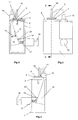
- Figs. 1-14 of the drawings illustrate a bench prototype (and components thereof) of a first embodiment of device suitable for delivering multiple doses of physiologically active agent in powdered form, built to test some of the principles involved. It is anticipated that, as in the later embodiments, the finished device will be capable of being reduced in size to be hand-held in use, and capable of being stored in a pocket or handbag when not in use.
- Figs 19 onwards illustrate more compact, hand-held devices.
- the device comprises a frame 1 of generally U-shaped cross section - see Figs. 1 and 2.
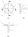
- a top plate 2 Secured to the top of the frame 1 is a top plate 2 having a recess 3 formed in its top planar surface. This recess 3 is generally cup-shaped and can be seen most clearly in Fig. 5.
- the top plate 2 combines with a spacer plate 4 and a nozzle plate 5 to form a powder metering unit for metering out a dose of powder from a bulk reservoir containing multiple doses of powder.
- the spacer plate 4 includes a main circular element 6 with a cylindrical hub 7 downwardly depending therefrom, as shown in Fig. 7.
- the cylindrical hub 7 is rotatably received in a bore provided in the top plate 2, to enable the spacer plate 4 (and nozzle plate 5 mounted thereon) to be rotatably indexed relative to the top plate 2 around the longitudinal axis of the hub 7, for reasons which will be explained later.
- the main circular element 6 Provided in the main circular element 6 are two angled drillings 8a, 8b aligned on a line radial to the longitudinal axis of the cylindrical hub 7. Spaced 90° therefrom with regard to said longitudinal axis, the main circular element 6 is also provided with an aperture 9 which converges downwardly in the manner of a hopper.
- the nozzle plate 5 is mounted on top of the plate 4 and is rotationally fast therewith.
- the space plate 4 and nozzle plate 5 were made separately in the embodiment of Figs. 1-14 purely for ease of manufacture.
- the nozzle plate 5 has two stub pipes 10,11 extending upwardly therefrom and positioned on a radial line with respect to the longitudinal axis of the cylindrical hub 7 of the spacer plate 4.
- the longest stub pipe models a nasal tube for insertion into the nostril of a patient.
- the shorter stub tube 11 is intended to have the end of a flexible tube fitted thereover (shown only in dotted lines 16), the flexible tube leading from the output of a manually rechargeable air reservoir 12 which will be described later.
- the flat surface of the nozzle plate 5 is also provided with an aperture 13.
- this aperture 13 is positioned over, and in alignment with, the aperture 9 provided in the spacer plate 4, as shown in Fig. 1, to form the base of a bulk reservoir for powder.
- the nasal tube 10 is positioned over, and in alignment with, drilling 8b of the spacer plate 4.
- the stub tube 11 is positioned over, and in alignment with, the upper end of the drilling 8a. As can be seen from Fig.
- the excess powder in the reservoir is transported away from the recess 3 and the powder in the receptacle 3 is scribed off flat by the edge at the base of aperture 9, to leave the recess 3 filled with a volume of powder equal to the internal volume of the recess 3.
- This volume of powder is known as a metered dose and by varying the volume of the recess 3 the size of the metered dose can obviously be changed.
- the bulk reservoir is likely to be both larger and sealed.
- the bulk reservoir formed by aligned apertures 9, 13 is very small (and unsealed) and can contain only a very small number of doses of powder.
- the powder metering unit formed by the top plate 2, spacer plate 4 and nozzle plate 5 can be used to meter accurately metered doses of powder from a bulk reservoir containing sufficient loose powder to make up multiple doses of powder.
- all of the frame 1, top plate 2, spacer plate 4 and nozzle plate 5 are made of metal, for example steel or aluminium.
- metal for example steel or aluminium.
- plastics material for reasons of both economy and light weight, such a material being well suited to moulding.
- the forced flow of gas used to discharge the metered dose of powder from the nasal tube 10 is provided by a manually rechargeable air reservoir 12 in the form of a bellows.
- the bellows is expandable and contractible as denoted by the double-headed arrow 13 in Fig. 2.
- the bellows is provided with a one way valve on its body, as indicated schematically at 14, as is the air exit 15 from the bellows. Consequently, in expanding the bellows, air enters the bellows via one way valve 14 (and not via bellows exit 15), whereas upon compression of the bellows air is forced from the bellows exit 15 (and not from valve 14).
- the flexible pipe 16 which would link the bellows exit 15 to the stub pipe 11 on the nozzle plate 5 has been represented schematically by a pair of dotted lines.
- the purpose of this flexible pipe is to channel the forced flow of air from the bellows 12 into the bore of the stub pipe 11, for use in entraining and discharging a metered dose of powder.
- the bellows 12 is expanded against the restoring bias of a compression spring 17.
- the bias of this spring can be modified by changing the position of a plunger 18, relative to a sidewall of the frame 1, but this is not envisaged as being necessary in a commercial device.
- the bellows 12 is not manually compressed by the user of the device; it is manually expanded. If the bellows were to be manually compressed, the velocity of the gas exiting the bellows exit 15 would be dependent upon the rate of compression of the bellows 12 by the user. Because the rate of gas exit from the bellows exit 15 can influence the way in which the powder of the metered dose is entrained and discharged, it is advantageous to be able to remove this variable from influence by the device user. Consequently, in the illustrated embodiment it is advantageous that all the user has to do, once the bellows 12 is primed (as shown in Fig. 2), is to trigger compression of the bellows 12 by raising the spring latch 20. The rate of compression of the bellows 12 is then determined by the bias of the spring 17.
- Figs. 15-18 illustrate an alternative triggering mechanism for a bellows.
- the surroundings to the mechanism are omitted.
- the spring 20 used to compress the bellows 21 will need to be braced against some other part of the device.
- an operating lever 22 is provided. At one end of the operating lever 22 the lever is hinged adjacent the bellows air exit 23. At the other end a latch 23 is pivotally attached to the lever 22. Upon lifting the latch end of the lever 22, engagement of the latch 23 with a pin 24 provided on one of the side walls of the bellows 21 causes the bellows to be expanded, as shown in Figs. 15 and 16. When the bellows 21 have been fully recharged with air, the latch 23 engages the underside of a stop peg 25, such that continued lifting movement of the lever 22 causes the stop peg 25 to pivot the latch 23 around its point of attachment to the lever 22, moving the hook provided at the base of the latch 23 free from engagement with the pin 24 (as shown in Fig.
- the bellows may be recharged with air, and then have its release triggered, all using one lever.
- the lever 22 could in one simple movement of the lever 22 both recharge the bellows with air and then release that charge of air, avoiding the need to have one lever or control for priming the rechargeable air reservoir and another control element for triggering release of air from the primed air reservoir.
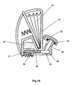
- Fig. 19 illustrates a second embodiment of device for delivering multiple doses of physiologically active agent in powdered form.
- the device is intended to be hand-held and comprises a main body which may advantageously be moulded in plastics material, as may most of the components of the device in this and the other embodiments.
- the main body 31 includes a nasal tube 32 for insertion in the nostril of a patient and defining internally a powder delivery passage.
- a closure 33 in the form of a hinged lid.
- the lid to tube seal may, as shown, be enhanced by the provision of an O-ring 34.
- the closure 33 also has the advantage of preventing debris from entering the device via the powder delivery passage.
- the bulk reservoir 35 containing multiple doses of powder has an aperture or exit 36 provided in its base surface.
- a powder metering slide 37 is positioned below the bulk reservoir 35 and is intended to slide linearly (horizontally as drawn) in a guide channel 38.
- the drug metering slide 37 is provided with a recess in the form of a through aperture 39 which, through sliding movement of the slide 37, can be moved from alignment with the bulk reservoir exit 36 (as shown in Fig. 19) to be aligned, instead, with the powder delivery passage provided in the nasal tube 32.
- the powder metering slide 37 When the powder metering slide 37 is in the position shown in Fig. 19, powder from the bulk reservoir 35 will, under the influence of gravity, enter and fill the aperture 39 provided in the slide 37.
- the aperture 39 may be transported into alignment with the powder delivery passage provided in the nasal tube 32, and with a passage 40 opening out of the base of the channel 38, which passage 40, in use, forms the upstream air supply passage (from the bellows 41).
- the top surface of the slide 37, to the left of the aperture 39 slides underneath the aperture 36 provided in the base of the bulk reservoir 35 to prevent powdered drug from falling out of the reservoir aperture 36 to foul the channel 38.
- the recess 39 formed in the slide forms a cup for metering out the required dose of powder.
- the arrangement for priming and triggering the bellows 41 in the second embodiment may be as in the first embodiment of Figs. 1-14, or may alternatively be as described above in connection with Figs. 15-18.
- the drug metering slide 37 is manually indexed by the user from the position shown to bring its aperture 39 into alignment with the downstream powder delivery passage, prior to the forced flow through the aperture 39 of air from the bellows 41. Once the device has been used to deliver a metered dose of powder, the slide 37 will need to be moved back to the left, to meter out a fresh dose of powder, prior to being moved back to the right, in order for the device to be used to deliver a subsequent dose.
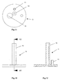
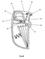
- the third embodiment of device avoids the need to have a separate manual action to index the drug metering slide, by linking this indexing movement with another task which the device user has to perform, namely movement of the closure covering the nasal tube.
- a powder metering slide 50 is provided which is movable linearly from having its powder receiving aperture or recess 51 aligned with the exit 52 from its bulk reservoir 53 to a position (to the right as drawn in Fig. 20) in which the metering slide's aperture 51 is positioned in line with an upstream air supply passage 54 (leading from the bellows exit) and a downstream powder delivery passage 55 formed by the nasal tube 56.
- the main difference between the second and third embodiments resides in the manner in which the powder metering slide 50 is moved between its two main positions.
- the closure 57 which closes the nasal tube 56 when the device is not in use, is attached to the main body of the device at a hinge point 58.
- the closure is, however, additionally connected to the drug metering slide 50 via a linkage 59.
- the linkage 59 acts as a pushrod to slide the powder metering slide 50 to the right, from the position shown in Fig. 20.
- the drug metering slide 50 will have been moved sufficiently far to the right that its aperture 51 will then be coaxially aligned with the upstream air supply passage 54 and the downstream powder delivery passage 55, making the device ready for use.
- the above described third embodiment of device should be simpler to use than the second embodiment of device in that it avoids the need for the device user to consciously index the powder metering slide manually.
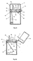
- Figures 21 and 22 illustrate a fourth embodiment of device. This device works on a similar principle to the previous devices.
- the fourth embodiment of device comprises a main element 60 incorporating the powder metering unit.
- a base housing 61 enclosing the bellows 62, seals against the main element 60, this seal being enhanced by the provision of an O-ring seal 63.
- a closure 64 in the form of a hinged cover, is attached to the base housing 61 by a hinge. To enhance sealing of the closure 64 to the main element 60 a further O-ring 65 is provided.
- the powder metering unit includes a metering slide 65.
- the recess provided in the slide for receiving the metered dose of powder comprises a U-shaped cup, opening only into the top face of the slide, such that the forced air flow to dislodge the metered dose of powder both enters and exits the powder-containing recess through the single aperture in the top face of the slide 65.
- the absence of a through hole in the slide 65 eliminates the possibility of particles falling downwardly through a hole in the slide, which is a possibility with the second and third embodiments described above.
- the metering slide 65 is movable between two main positions.
- the first position is one in which the recess in the metering slide can receive powder from the bulk reservoir 66, in which position it is isolated from both the upstream air supply passage 67 and the downstream powder delivery passage 68. This first position is shown in Fig. 21.
- the second main position for the metering slide is shown in Fig. 22.
- the recess in the metering slide is coincident with both the upstream air supply passage 67 and the downstream powder delivery passage 68 and is isolated from the bulk reservoir 66.
- the fourth embodiment it is the action of the powder-containing recess formed in the metering slide moving out of alignment with the powder exit from the bulk reservoir 66 which controls the amount of powder in the metered dose.
- the fourth embodiment is constructed and arranged so that the metering unit is operated by the action of moving the closure 64.
- the metering slide is provided with a flexible linkage 69 which is pivotally attached to a hook 70 at the right hand end of the channel in which the slide moves.
- the flexible linkage 69 is sufficiently stiff and resilient, for example being made of plastics material, that when not acted upon by external influences it will straighten (as shown in Fig. 22), causing the metering slide to move to the aforementioned second position.
- the closure 64 when, prior to using the device to discharge powdered drug, the closure 64 is opened, the metering slide will move automatically from its first position to its second position, to carry a metered dose of powder into alignment with the air supply and powder delivery passages, 67,68. In this condition, the forced flow of gas from the manually rechargeable air reservoir, in the form of bellows 62, will deliver the powder in the manner discussed above.
- moisture can have an adverse effect.
- moisture ingress into the device can adversely affect the delivered dose of agent by coating surfaces and causing agglomeration of the powder.
- the design of the fourth embodiment of device is effective in restricting the unwanted ingress of air (and thus moisture) into the device when the device is not in use.
- closure 64 prevents unwanted ingress of ambient air (and moisture) through the powder delivery passage in the nasal tube, but it also has the effect of sealing the apertures 72,74 such that the maximum amount of moisture that can be present in the device will be that present in the device, and the air trapped in the device, at the time the closure 64 is closed after use.
- closure 64 is shown as being hinged to the remainder of the device, it will be appreciated that the closure 64 could equally well be completely detachable from the remainder of the device, such that to open the closure one removes it from the remainder of the device and replaces it after use.
- the hinged arrangement in Figs. 21 and 22 is preferred because it prevents the closure 64 from being detached and getting lost.
- the powder metering slide 65 moves from its first position to its second position (on opening) and from its second position back to its first position (on closing), other movement possibilities are envisaged.
- the metering slide 65 might start at its second position, move initially to its first position (to receive a metered dose of powder) and then move back to the second position.
- there might be a third position for the metering slide in which the powder-containing recess in the slide is neither capable of receiving powder from the bulk reservoir 66 nor coincident with either of the air supply passage 67 or the powder delivery passage 68, and from which, when the closure 64 is opened, the slide 65 is moved to the first position and then to the second position.
- the metering slide 65 might be moved to its first position by the action of opening the closure, although in this case some means would need to be provided to move the slide subsequently to its second position prior to activation of the device to discharge the powder.
- the bellows 62 may take the form of any of the bellows described above, with regard to charging and/or triggering release of a charge of air.
- priming of the bellows could advantageously be linked to another operation which the user of the device already has to perform.
- priming of the bellows might also be linked to the action of opening or closing the closure 64.
- the bellows 62 might also be primed (i.e.
- triggering of the release of the bellows could also be linked to movement of the closure 64.
- part of the full range of movement of the closure 64 might be used to move the metering slide 65 to its second position and to charge the bellows 62, with the final portion of the closure's range of movement being used to trigger release of the bellows, i.e. to "fire" the device.
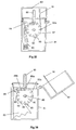
- Figs. 23 and 24 of the application is fundamentally similar to that of the fourth embodiment of Figs. 21 and 22.
- similar parts have been given the same reference numerals as in Figs. 21 and 22.
- the main difference, apart from a slight change in general layout, is in the arrangement of the linkage 69.
- the right hand end of the linkage 69 is attached to the closure 64, rather than to a hook 70 provided at the stationary right hand side of the main element 60. In this way, the need to have a downwardly depending element 71 to displace the linkage 69 laterally can be avoided.
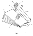
- each of the devices is provided with a powder container defining therein a plurality of individual receptacles, each receptacle containing a discrete metered dose of powder. This avoids the need for a dose of powder to be metered within the device; instead, the doses can be pre-metered in a factory before the powder container is associated with the remainder of the device.
- the device comprises a base housing 81 having an openable closure 82 attached thereto by a hinge.
- a bellows 83 is provided in the base housing and feeds into the upstream end of an upstream air supply passage 84.
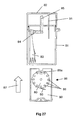
- This air supply passage terminates at a downstream end that is aligned with, but spaced apart from, the upstream end of a downstream drug delivery passage 85.
- This spacing is equivalent to the axial thickness of the powder container 80; such that when a removable cassette 86 housing the powder container 80 is slid (in the direction of arrow 87 in Fig. 27) into the open bottom of the base housing 81, a circumferential portion of the rotatable powder container 80 will be snugly received in the gap between the downstream end of the upstream air supply passage 84 and the upstream end of the downstream drug delivery passage 85.
- the powder container 80 is provided in the region of its circumference with twelve receptacles 88 in the form of throughbores. Each of these throughbores 88 is sized to contain a discrete pre-metered dose of powder for delivery.
- the powder container 80 is mounted on a spindle 89 to allow it to be rotatably indexed, as will be described below. In the position shown in Fig. 27, only the open first and second opposite ends of the uppermost throughbore 88a are exposed. The opposite ends of the remaining eleven throughbores are closed by the main walls 90 of the removable cassette 86, only one of these walls 90 being visible in Fig. 27. Consequently, the metered doses of powder contained within these eleven closed throughbores are prevented from leaking out of the throughbores - any leakage would be undesirable as it could lead to underdosing.
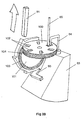
- a flexible indexing finger 91 will move into contact with one of the twelve gear teeth 92 provided around the periphery of the powder container 80.
- the tip of the flexible indexing finger 91 will come into contact with the gear tooth 92a in the 2 o'clock position (as drawn in Fig. 26).
- Continued closing of the closure 82 after this finger-to-tooth contact is established will rotate the powder container 80 through 1/12 of a turn in the clockwise direction, such that the geartooth 92a ends up in the 3 o'clock position, as shown in Fig.
- a pawl 93 is provided to cooperate with the gear teeth 92 of the ratchet-like container 80.
- the powder container 80 as well as the body of the removable cassette 86, the base housing 81 and the closure 82 are injection moulded in an engineering plastics material.
- the cassette 86 can be removed from the device by pulling on the integrally moulded handle 94 and the removed cassette 86 discarded. In its place, an entirely fresh replacement cassette 86 can be inserted, to enable the device to be used for a further twelve dosing events.
- the powder container could be provided with greater or fewer powder-containing receptacles.
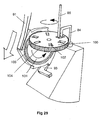
- a separate gear wheel can be provided between the flexible indexing finger 91 and the powder container 100.
- a gear wheel 101 is provided with its number of gear teeth matching the number of powder-containing receptacles provided in the powder container 100, this number being six in the illustrated arrangement.
- FIG. 28 and 29 A further difference between the arrangement illustrated in Figs. 28 and 29, and that illustrated in Figs. 25-27, is that in the Fig. 28 and 29 arrangement the powder containing receptacles 102 are not throughbores but are instead cup-shaped. Consequently, only the upper surface of the powder container 100 has openings formed therein and the upstream air supply passage 84 and the downstream drug delivery passage 85 both face into the receptacles 102 (when aligned therewith) through this single, upwardly facing opening.
- a face plate with a small sector cut away around the downstream end of the upstream air supply passage 84 and the upstream end of the downstream drug delivery passage 85 may be placed over the top of the powder container 100 so that only one powder-containing receptacle 102 is open at any given time.
- a foil membrane could be provided over each of the receptacles, which membrane is slit or otherwise ruptured prior to the contents of the respective receptacle being discharged. This would enhance the protection of the doses against degradation from airborne moisture.
- the manually rechargeable air reservoir takes the form of an inflatable bellows provided with a spring bias, with the bellows being expanded against the spring bias to charge the bellows with air
- these means may alternatively take the form of a cylinder and piston arrangement.
- the piston could be provided with a spring bias, with the piston being moved against the spring bias to sweep the cylinder to charge the cylinder with air ready for triggering and air release.
Landscapes
- Health & Medical Sciences (AREA)
- Engineering & Computer Science (AREA)
- Life Sciences & Earth Sciences (AREA)
- Anesthesiology (AREA)
- Pulmonology (AREA)
- Biomedical Technology (AREA)
- Heart & Thoracic Surgery (AREA)
- Hematology (AREA)
- Bioinformatics & Cheminformatics (AREA)
- Animal Behavior & Ethology (AREA)
- General Health & Medical Sciences (AREA)
- Public Health (AREA)
- Veterinary Medicine (AREA)
- Biophysics (AREA)
- Infusion, Injection, And Reservoir Apparatuses (AREA)
- Medical Preparation Storing Or Oral Administration Devices (AREA)
Claims (26)
- Vorrichtung zur Verabreichung von mehreren Dosen eines physiologisch aktiven Mittels in Pulverform, wobei die Vorrichtung umfasst:ein manuell wiederaufladbares Luftreservoir (83);einen Pulverbehälter (80, 100), welcher darin mehrere individuelle Aufnahmen (88, 88a, 88b, 102) definiert, wobei jede Aufnahme eine separate abgemessene Dosis des Pulvers enthält,einen Pulververabreichungskanal (85) für den erzwungenen Luftstrom dort entlang zu einem Patienten, wobei die abgemessene Dosis des Pulvers darin im Wesentlichen derart mitgerissen wird, dass die Aufnahme entleert wird,einen Verschluss (82), um das unerwünschte Eindringen von Feuchtigkeit in die Vorrichtung über den Kanal zu begrenzen, wenn sich die Vorrichtung nicht im Betrieb befindet; undeinen Mechanismus (91, 92) zum Indizieren des Behälters, um eine Bewegung des Behälters derart zu indizieren, dass eine im Wesentlichen leere Aufnahme (88a) aus einer Verbindung mit dem Arzneimittelverabreichungskanal bewegt wird und eine frische das Pulver enthaltende der Aufnahmen (88b) in eine Verbindung mit dem Pulververabreichungskanal bewegt wird;wobei die Vorrichtung derart konstruiert und angeordnet ist, dass der Vorgang eines Öffnens und Verschließens des Verschlusses (i) den Mechanismus zum Indizieren des Behälters betreibt und (ii) das Luftreservoir mit Luft auflädt.
- Vorrichtung nach Anspruch 1, wobei der Mechanismus (91, 92) zum Indizieren des Behälters derart ausgestaltet ist, dass eine indizierende Bewegung bei dem Vorgang des Öffnens des Verschlusses (82) bei einer Vorbereitung zur Verwendung der Vorrichtung zur Verabreichung des Pulvers ausgeführt wird.
- Vorrichtung nach Anspruch 1 oder Anspruch 2, wobei der Pulverbehälter (80) derart angeordnet ist, dass er sich um eine Achse (89) dreht, wenn eine indizierende Bewegung ausgeführt wird.
- Vorrichtung nach einem der vorhergehenden Ansprüche, weiter einen Luftzuführungskanal (84) für den erzwungenen Luftstrom dort entlang von dem Luftreservoir (83) umfassend, wobei, wenn sich eine der Aufnahmen (88, 102) in Verbindung mit dem Pulververabreichungskanal (85) befindet, dieselbe Aufnahme auch in Verbindung mit dem Luftzuführungskanal steht, wobei der erzwungene Luftstrom entlang dem Luftzuführungskanal verwendet werden kann, um die separate abgemessene Dosis des Pulvers von der Aufnahme zu entladen und das entladene Pulver in der Luft mitzureißen, um das mitgerissene Pulver über den Pulververabreichungskanal dem Patienten zu verabreichen.
- Vorrichtung nach Anspruch 4, wobei jede Aufnahme (102), welche in, dem Pulverbehälter vorhanden ist, im Allgemeinen becherförmig ist und eine einzige Öffnung aufweist, wobei jede Aufnahme derart angeordnet ist, dass sie mit dem Luftzuführungskanal , und mit dem Pulververabreichungskanal über ihre einzige Öffnung in Verbindung steht.
- Vorrichtung nach Anspruch 4, wobei jede Aufnahme, welche in dem Pulverbehälter (80) vorhanden ist, eine Durchgangsbohrung (88) ist, welche ein erstes und ein zweites Ende aufweist, die einander gegenüberliegen, wobei jedes Reservoir derart angeordnet ist, dass es mit dem Luftzuführungskanal (84) bzw. dem Pulververabreichungskanal (85) über sein erstes bzw. sein zweites Ende in Verbindung steht, so dass im Betrieb der erzwungene Luftstrom im Allgemeinen in Längsrichtung durch das Bohrloch verläuft.
- Vorrichtung nach einem der vorhergehenden Ansprüche, wobei der Mechanismus zum Indizieren des Behälters ein indizierendes Element (91) umfasst, welches derart ausgestaltet ist, dass es sich bei dem Öffnen oder dem Schließen des Verschlusses (82) bewegt, wobei das Element derart ausgestaltet ist, dass es eine Bewegung des Pulverbehälters (80) indiziert.
- Vorrichtung nach Anspruch 7, wobei das indizierende Element (91) derart ausgestaltet ist, dass es direkt auf den Pulverbehälter (80) wirkt, um die indizierende Bewegung zu bewirken.
- Vorrichtung nach Anspruch 8, wobei das indizierende Element einen flexiblen indizierenden Finger (91) umfasst, wobei der Finger derart angeordnet ist, dass er den Umfang des Pulverbehälters (80) derart berührt, dass er die indizierende Bewegung bewirkt.
- Vorrichtung nach Anspruch 8, wobei das indizierende Element (91) derart ausgestaltet ist, dass es indirekt auf den Pulverbehälter (100) derart einwirkt, dass es die indizierende Bewegung bewirkt.
- Vorrichtung nach Anspruch 10, wobei das indizierende Elements einen flexiblen indizierenden Finger (91) umfasst, wobei der Finger derart ausgestaltet ist, dass er auf ein Zahnrad (101) wirkt, welches getrennt von dem Pulverbehälter (100) angeordnet ist und sich mit diesem in Eingriff befindet.
- Vorrichtung nach Anspruch 9 oder Anspruch 11, wobei die Spitze des flexiblen indizierenden Fingers (91) derart ausgestaltet ist, dass sie derart einen Getriebezahn (92) berührt und schiebt, dass eine Bewegung im Allgemeinen in Längsrichtung des flexiblen indizierenden Fingers in eine im Allgemeinen drehende Bewegung des Pulverbehälters (80) umgesetzt wird.
- Vorrichtung nach Anspruch 12, wobei die Getriebezähne (92) einer Sperrklinke ähnlich sind und eine Klaue (93) vorhanden ist, um eine unerwünschte Bewegung der Sperrklinke zu verhindern.
- Vorrichtung nach einem der vorhergehenden Ansprüche, wobei das Luftreservoir (83) derart konstruiert und angeordnet ist, dass es durch den Vorgang des Öffnens des Verschlusses (82) in einer Vorbereitung zur Verwendung der Vorrichtung zur Verabreichung des Pulvers mit Luft frisch geladen wird.
- Vorrichtung nach einem der vorhergehenden Ansprüche, weiter eine Kopplung zwischen dem Reservoir und dem Verschluss umfassend.
- Vorrichtung nach Anspruch 15, wobei der Verschluss zwischen seiner offenen und seiner geschlossenen Position schwenkbar ist und die Kopplung derart ausgestaltet ist, dass sie zumindest einen Teil der Schwenkbewegung des Verschlusses in eine Bewegung eines Teils des Reservoir derart umsetzt, dass bewirkt wird, dass Luft derart in das Reservoir eingesaugt wird, dass es wieder aufgeladen wird.
- Vorrichtung nach einem der vorhergehenden Ansprüche, wobei das Reservoir einen Zylinder umfasst, wobei ein Kolben gleitend und abdichtend darin aufgenommen ist.
- Vorrichtung nach einem der Ansprüche 1 bis 16, wobei das Reservoir ein Balg (83) ist.
- Vorrichtung nach Anspruch 17 oder Anspruch 18, wobei der Kolben oder der Balg (83) gegen eine Vorspannfeder von einem das Reservoir entladenden Zustand in einen das Reservoir aufladenden Zustand, um so dass Reservoir mit Luft wiederaufzuladen, versetzbar ist.
- Vorrichtung nach Anspruch 19, wobei eine Verriegelungsanordnung vorhanden ist, um den Kolben oder den Balg in dem aufgeladenen Zustand zu verriegeln.
- Vorrichtung nach Anspruch 20, wobei die Verriegelungsanordnung lösbar ist, um den Kolben oder den Balg unter dem Einfluss der Vorspannfeder von seinem aufgeladenen Zustand in seinen entladenden Zustand verändern zu können.
- Vorrichtung nach Anspruch 20 oder Anspruch 21, wobei die Verriegelungsanordnung mit einem manuell betreibbaren Auslöser versehen ist, um sie zu lösen.
- Vorrichtung nach einem der Ansprüche 20 bis 22, wobei die Verriegelungsanordnung derart ausgestaltet ist, dass sie durch eine Bewegung des Verschlusses gelöst wird.
- Vorrichtung nach einem der vorhergehenden Ansprüche, wobei das physiologisch aktive Mittel in Pulverform eine Verbindung oder eine Zusammensetzung einer Substanz ist, welche, wenn sie einem Organismus verabreicht wird, einen erwünschten pharmakologischen und/oder physiologischen Effekt durch einen lokalen und/oder systemischen Vorgang induziert.
- Vorrichtung nach einem der vorhergehenden Ansprüche, wobei das physiologisch aktive Mittel in Pulverform ein Arzneimittel, ein Biopharmazeutikum, ein Impfstoff oder eine Gentherapie ist.
- Vorrichtung nach einem der vorhergehenden Ansprüche, wobei die Vorrichtung derart konstruiert und angeordnet ist, dass sie zur Verabreichung von mehreren Dosen eines physiologisch aktiven Mittels in Pulverform in die Nasenhöhle eines Objektes eingesetzt wird.
Applications Claiming Priority (3)
| Application Number | Priority Date | Filing Date | Title |
|---|---|---|---|
| GB0019715 | 2000-08-10 | ||
| GBGB0019715.2A GB0019715D0 (en) | 2000-08-10 | 2000-08-10 | Device for delivering physiologically active agent in powdered form |
| PCT/GB2001/003555 WO2002011800A2 (en) | 2000-08-10 | 2001-08-08 | Device for delivering physiologically active agent in powdered form |
Publications (2)
| Publication Number | Publication Date |
|---|---|
| EP1322356A1 EP1322356A1 (de) | 2003-07-02 |
| EP1322356B1 true EP1322356B1 (de) | 2007-12-05 |
Family
ID=9897388
Family Applications (1)
| Application Number | Title | Priority Date | Filing Date |
|---|---|---|---|
| EP01954194A Expired - Lifetime EP1322356B1 (de) | 2000-08-10 | 2001-08-08 | Vorrichtung zur verabreichung von physiologisch aktiven wirkstoffen in pulverform |
Country Status (9)
| Country | Link |
|---|---|
| US (1) | US7275537B2 (de) |
| EP (1) | EP1322356B1 (de) |
| JP (1) | JP2004509669A (de) |
| AU (2) | AU2001276538B2 (de) |
| CA (1) | CA2418906A1 (de) |
| DE (1) | DE60131760T2 (de) |
| ES (1) | ES2295187T3 (de) |
| GB (1) | GB0019715D0 (de) |
| WO (1) | WO2002011800A2 (de) |
Cited By (1)
| Publication number | Priority date | Publication date | Assignee | Title |
|---|---|---|---|---|
| US11154665B2 (en) | 2015-06-24 | 2021-10-26 | Ethicon, Inc. | Hemostatic powder delivery devices and methods |
Families Citing this family (24)
| Publication number | Priority date | Publication date | Assignee | Title |
|---|---|---|---|---|
| US6082358A (en) | 1998-05-05 | 2000-07-04 | 1263152 Ontario Inc. | Indicating device for aerosol container |
| GB0216556D0 (en) * | 2002-07-17 | 2002-08-28 | Reckitt Benckiser Uk Ltd | Dispenser |
| GB0303870D0 (en) * | 2003-02-20 | 2003-03-26 | Norton Healthcare Ltd | Pre-metered dose magazine for breath-actuated dry powder inhaler |
| FI20031158A (fi) * | 2003-08-15 | 2005-02-16 | Perlos Oyj | Inhalaattori |
| FR2881118B1 (fr) * | 2005-01-25 | 2007-04-20 | Valois Sas | Dispositif de distribution de produit fluide. |
| FR2881117B1 (fr) * | 2005-01-25 | 2010-07-30 | Valois Sas | Dispositif de distribution de produit fluide. |
| TWI442951B (zh) * | 2005-04-14 | 2014-07-01 | Astrazeneca Ab | 吸入器計量器 |
| US7614429B2 (en) | 2005-05-18 | 2009-11-10 | Symyx Solutions, Inc. | Apparatus and methods for storing and dispensing solid material |
| JP4500280B2 (ja) * | 2005-06-08 | 2010-07-14 | 日立オートモティブシステムズ株式会社 | 粉末薬剤投与器 |
| GB0515584D0 (en) * | 2005-07-28 | 2005-09-07 | Glaxo Group Ltd | Medicament dispenser |
| DE102006043637A1 (de) * | 2006-05-18 | 2007-11-22 | Boehringer Ingelheim Pharma Gmbh & Co. Kg | Zerstäuber |
| US20100269819A1 (en) * | 2006-08-14 | 2010-10-28 | Sievers Robert E | Human Powered Dry Powder Inhaler and Dry Powder Inhaler Compositions |
| EP2112923A1 (de) | 2007-01-22 | 2009-11-04 | Targacept Inc. | Intranasale, orale und sublinguale verabreichung von metanikotin-analogen |
| GB0704928D0 (en) * | 2007-03-14 | 2007-04-25 | Cambridge Consultants | Dry powder inhalers |
| EP2042208A1 (de) * | 2007-09-25 | 2009-04-01 | Boehringer Ingelheim Pharma GmbH & Co. KG | Abgabevorrichtung |
| EP2082759A1 (de) † | 2008-01-24 | 2009-07-29 | Boehringer Ingelheim International GmbH | Inhalator |
| US20100127022A1 (en) * | 2008-11-21 | 2010-05-27 | Symyx Technologies, Inc. | Dispensing valve |
| EP3260152B1 (de) | 2009-05-18 | 2019-12-18 | Adamis Pharmaceuticals Corporation | Trockenpulverinhalatoren |
| AT13748U1 (de) * | 2013-05-29 | 2014-08-15 | Boehringer Ingelheim Int | Zerstäuber |
| US20170197047A1 (en) * | 2016-01-08 | 2017-07-13 | Inertia Engineering + Design Inc. | Portable electromechanical resuscitator bag compression device |
| WO2023135237A1 (en) | 2022-01-14 | 2023-07-20 | Cybin Irl Limited | Tryptamine compositions and methods |
| WO2023156450A1 (en) | 2022-02-15 | 2023-08-24 | Cybin Irl Limited | Therapeutic phenethylamine compositions and methods of use |
| WO2023156453A1 (en) | 2022-02-15 | 2023-08-24 | Cybin Irl Limited | Phenethylamine derivatives, compositions, and methods of use |
| WO2023186963A1 (en) | 2022-03-31 | 2023-10-05 | Cybin Irl Limited | Combination of nitrous oxide and 5-ht2a receptor agonists |
Citations (3)
| Publication number | Priority date | Publication date | Assignee | Title |
|---|---|---|---|---|
| WO1994011044A2 (en) * | 1992-11-12 | 1994-05-26 | Minnesota Mining And Manufacturing Company | Powder inhaler |
| US5740792A (en) * | 1992-12-18 | 1998-04-21 | Schering Corporation | Inhaler for powdered medications with gear-teeth counter assembly |
| US5921237A (en) * | 1995-04-24 | 1999-07-13 | Dura Pharmaceuticals, Inc. | Dry powder inhaler |
Family Cites Families (25)
| Publication number | Priority date | Publication date | Assignee | Title |
|---|---|---|---|---|
| GB1479283A (en) * | 1973-07-23 | 1977-07-13 | Bespak Industries Ltd | Inhaler for powdered medicament |
| US4274403A (en) * | 1979-08-29 | 1981-06-23 | Struve Roger L | Inhaler |
| GB8810898D0 (en) | 1988-05-09 | 1988-06-15 | Bespak Plc | Improvements in dispensing apparatus |
| GB8909891D0 (en) * | 1989-04-28 | 1989-06-14 | Riker Laboratories Inc | Device |
| DE4027749A1 (de) * | 1990-09-01 | 1992-03-05 | Pfeiffer Erich Gmbh & Co Kg | Austragvorrichtung fuer medien |
| DE69132850T2 (de) | 1990-09-26 | 2002-05-29 | Pharmachemie Bv | Wirbelkammer-Pulverinhalator |
| AU8720791A (en) | 1990-10-12 | 1992-05-20 | Novo Nordisk A/S | Disposable dispenser for powder |
| GB2251898A (en) | 1990-11-29 | 1992-07-22 | D M W | Metered dose spray system |
| US5161524A (en) * | 1991-08-02 | 1992-11-10 | Glaxo Inc. | Dosage inhalator with air flow velocity regulating means |
| JPH06504223A (ja) | 1991-08-15 | 1994-05-19 | デル・ボン・フランコ | 吸入器 |
| GB9123953D0 (en) | 1991-11-12 | 1992-01-02 | Minnesota Mining & Mfg | Inhalation device |
| GB9203761D0 (en) * | 1992-02-21 | 1992-04-08 | Innovata Biomed Ltd | Inhaler |
| GB9218937D0 (en) | 1992-09-08 | 1992-10-21 | Norton Healthcare Ltd | Medicament dispensing device |
| DE4227899A1 (de) * | 1993-09-24 | 1994-02-24 | Pfeiffer Erich Gmbh & Co Kg | Austrageeinrichtung für fließfähige Medien |
| DE19518810A1 (de) * | 1995-05-26 | 1996-11-28 | Bayer Ag | Nasal-Applikator |
| JPH1028735A (ja) | 1996-05-11 | 1998-02-03 | Unisia Jecs Corp | 鼻腔用投薬器 |
| GB9700226D0 (en) | 1997-01-08 | 1997-02-26 | Glaxo Group Ltd | Inhalation device |
| GB9702688D0 (en) | 1997-02-10 | 1997-04-02 | Bespak Plc | A dispensing apparatus |
| HU224242B1 (hu) * | 1998-01-30 | 2005-06-28 | IG Sprühtechnik GmbH & Co. KG | Inhaláló por alakú gyógyszerekhez |
| GB9820900D0 (en) * | 1998-09-26 | 1998-11-18 | Glaxo Group Ltd | Inhalation device |
| EP1222672A2 (de) * | 1999-10-06 | 2002-07-17 | Nordic Superconductor Technologies A/S | Verfahren zur herstellung und verwendung eines supraleiterbandes, insbesondere zum wickeln einer spule. |
| EP1220698B1 (de) * | 1999-10-12 | 2004-07-21 | SHL Medical AB | Inhalateur |
| US7171965B2 (en) * | 2000-02-01 | 2007-02-06 | Valois S.A.S. | Breath actuated dry powder inhaler and tape dose strip |
| GB0015034D0 (en) * | 2000-06-21 | 2000-08-09 | Glaxo Group Ltd | Inhalation device |
| KR20060036104A (ko) | 2003-07-28 | 2006-04-27 | 콸콤 인코포레이티드 | 발진기의 주파수 편이 파라미터를 추정하는 절차 |
-
2000
- 2000-08-10 GB GBGB0019715.2A patent/GB0019715D0/en not_active Ceased
-
2001
- 2001-08-08 CA CA002418906A patent/CA2418906A1/en not_active Abandoned
- 2001-08-08 JP JP2002517132A patent/JP2004509669A/ja active Pending
- 2001-08-08 ES ES01954194T patent/ES2295187T3/es not_active Expired - Lifetime
- 2001-08-08 AU AU2001276538A patent/AU2001276538B2/en not_active Ceased
- 2001-08-08 EP EP01954194A patent/EP1322356B1/de not_active Expired - Lifetime
- 2001-08-08 WO PCT/GB2001/003555 patent/WO2002011800A2/en active IP Right Grant
- 2001-08-08 DE DE60131760T patent/DE60131760T2/de not_active Expired - Fee Related
- 2001-08-08 AU AU7653801A patent/AU7653801A/xx active Pending
- 2001-08-08 US US10/344,130 patent/US7275537B2/en not_active Expired - Fee Related
Patent Citations (3)
| Publication number | Priority date | Publication date | Assignee | Title |
|---|---|---|---|---|
| WO1994011044A2 (en) * | 1992-11-12 | 1994-05-26 | Minnesota Mining And Manufacturing Company | Powder inhaler |
| US5740792A (en) * | 1992-12-18 | 1998-04-21 | Schering Corporation | Inhaler for powdered medications with gear-teeth counter assembly |
| US5921237A (en) * | 1995-04-24 | 1999-07-13 | Dura Pharmaceuticals, Inc. | Dry powder inhaler |
Cited By (2)
| Publication number | Priority date | Publication date | Assignee | Title |
|---|---|---|---|---|
| US11154665B2 (en) | 2015-06-24 | 2021-10-26 | Ethicon, Inc. | Hemostatic powder delivery devices and methods |
| US11717619B2 (en) | 2015-06-24 | 2023-08-08 | Ethicon, Inc. | Hemostatic powder delivery devices and methods |
Also Published As
| Publication number | Publication date |
|---|---|
| DE60131760D1 (de) | 2008-01-17 |
| AU2001276538B2 (en) | 2006-08-10 |
| JP2004509669A (ja) | 2004-04-02 |
| GB0019715D0 (en) | 2000-09-27 |
| AU2001276538C1 (en) | 2002-02-18 |
| EP1322356A1 (de) | 2003-07-02 |
| US20030183230A1 (en) | 2003-10-02 |
| DE60131760T2 (de) | 2008-11-13 |
| WO2002011800A2 (en) | 2002-02-14 |
| AU7653801A (en) | 2002-02-18 |
| ES2295187T3 (es) | 2008-04-16 |
| CA2418906A1 (en) | 2002-02-14 |
| US7275537B2 (en) | 2007-10-02 |
Similar Documents
| Publication | Publication Date | Title |
|---|---|---|
| EP1322356B1 (de) | Vorrichtung zur verabreichung von physiologisch aktiven wirkstoffen in pulverform | |
| AU2001276538A1 (en) | Device for delivering physiologically active agent in powdered form | |
| AU2005209199B2 (en) | Sublingual drug delivery device | |
| JP4497730B2 (ja) | 複合薬剤用の粉末吸入器 | |
| AU2019222959B2 (en) | Dry powder inhaler and inhalation actuated mechanism thereof | |
| JP2010512876A5 (de) | ||
| MX2008011620A (es) | Inhalador para sustancias pulverulentas. | |
| SE0003408D0 (sv) | Continuous dry powder inhaler | |
| KR20090126236A (ko) | 분말 형태의 약을 위한 흡입 장치 | |
| HU216770B (hu) | Inhalálókészülék por alakú gyógyszerkészítmények adagolására | |
| JP2004509669A5 (de) | ||
| PL182513B1 (pl) | Urządzenie do inhalacji oraz sposób inhalacji | |
| CA2225396A1 (en) | Pharmaceutical powder cartridge with integrated metering device and inhaler for powdered medicaments | |
| JP2002541988A (ja) | 粉末吸入器 | |
| NZ726772B2 (en) | Dry powder inhaler and inhalation actuated mechanism thereof |
Legal Events
| Date | Code | Title | Description |
|---|---|---|---|
| PUAI | Public reference made under article 153(3) epc to a published international application that has entered the european phase |
Free format text: ORIGINAL CODE: 0009012 |
|
| 17P | Request for examination filed |
Effective date: 20030221 |
|
| AK | Designated contracting states |
Designated state(s): AT BE CH CY DE DK ES FI FR GB GR IE IT LI LU MC NL PT SE TR |
|
| AX | Request for extension of the european patent |
Extension state: AL LT LV MK RO SI |
|
| RBV | Designated contracting states (corrected) |
Designated state(s): DE ES FR GB IT |
|
| 17Q | First examination report despatched |
Effective date: 20041214 |
|
| GRAP | Despatch of communication of intention to grant a patent |
Free format text: ORIGINAL CODE: EPIDOSNIGR1 |
|
| GRAS | Grant fee paid |
Free format text: ORIGINAL CODE: EPIDOSNIGR3 |
|
| GRAA | (expected) grant |
Free format text: ORIGINAL CODE: 0009210 |
|
| AK | Designated contracting states |
Kind code of ref document: B1 Designated state(s): DE ES FR GB IT |
|
| REG | Reference to a national code |
Ref country code: GB Ref legal event code: FG4D |
|
| REF | Corresponds to: |
Ref document number: 60131760 Country of ref document: DE Date of ref document: 20080117 Kind code of ref document: P |
|
| REG | Reference to a national code |
Ref country code: ES Ref legal event code: FG2A Ref document number: 2295187 Country of ref document: ES Kind code of ref document: T3 |
|
| ET | Fr: translation filed | ||
| RAP2 | Party data changed (patent owner data changed or rights of a patent transferred) |
Owner name: PFIZER LIMITED |
|
| PLBE | No opposition filed within time limit |
Free format text: ORIGINAL CODE: 0009261 |
|
| STAA | Information on the status of an ep patent application or granted ep patent |
Free format text: STATUS: NO OPPOSITION FILED WITHIN TIME LIMIT |
|
| PGFP | Annual fee paid to national office [announced via postgrant information from national office to epo] |
Ref country code: ES Payment date: 20080808 Year of fee payment: 8 Ref country code: DE Payment date: 20080204 Year of fee payment: 8 |
|
| 26N | No opposition filed |
Effective date: 20080908 |
|
| PGFP | Annual fee paid to national office [announced via postgrant information from national office to epo] |
Ref country code: IT Payment date: 20080826 Year of fee payment: 8 |
|
| PGFP | Annual fee paid to national office [announced via postgrant information from national office to epo] |
Ref country code: GB Payment date: 20080806 Year of fee payment: 8 |
|
| PGFP | Annual fee paid to national office [announced via postgrant information from national office to epo] |
Ref country code: FR Payment date: 20080820 Year of fee payment: 8 |
|
| GBPC | Gb: european patent ceased through non-payment of renewal fee |
Effective date: 20090808 |
|
| REG | Reference to a national code |
Ref country code: FR Ref legal event code: ST Effective date: 20100430 |
|
| PG25 | Lapsed in a contracting state [announced via postgrant information from national office to epo] |
Ref country code: FR Free format text: LAPSE BECAUSE OF NON-PAYMENT OF DUE FEES Effective date: 20090831 Ref country code: DE Free format text: LAPSE BECAUSE OF NON-PAYMENT OF DUE FEES Effective date: 20100302 |
|
| REG | Reference to a national code |
Ref country code: ES Ref legal event code: FD2A Effective date: 20090810 |
|
| PG25 | Lapsed in a contracting state [announced via postgrant information from national office to epo] |
Ref country code: GB Free format text: LAPSE BECAUSE OF NON-PAYMENT OF DUE FEES Effective date: 20090808 |
|
| PG25 | Lapsed in a contracting state [announced via postgrant information from national office to epo] |
Ref country code: IT Free format text: LAPSE BECAUSE OF NON-PAYMENT OF DUE FEES Effective date: 20090808 |
|
| PG25 | Lapsed in a contracting state [announced via postgrant information from national office to epo] |
Ref country code: ES Free format text: LAPSE BECAUSE OF NON-PAYMENT OF DUE FEES Effective date: 20090809 |