EP1322356B1 - Device for delivering physiologically active agent in powdered form - Google Patents
Device for delivering physiologically active agent in powdered form Download PDFInfo
- Publication number
- EP1322356B1 EP1322356B1 EP01954194A EP01954194A EP1322356B1 EP 1322356 B1 EP1322356 B1 EP 1322356B1 EP 01954194 A EP01954194 A EP 01954194A EP 01954194 A EP01954194 A EP 01954194A EP 1322356 B1 EP1322356 B1 EP 1322356B1
- Authority
- EP
- European Patent Office
- Prior art keywords
- powder
- air
- closure
- reservoir
- indexing
- Prior art date
- Legal status (The legal status is an assumption and is not a legal conclusion. Google has not performed a legal analysis and makes no representation as to the accuracy of the status listed.)
- Expired - Lifetime
Links
- 239000013543 active substance Substances 0.000 title claims abstract description 24
- 239000000843 powder Substances 0.000 claims abstract description 173
- 230000009471 action Effects 0.000 claims abstract description 18
- 238000004891 communication Methods 0.000 claims abstract description 11
- 210000003928 nasal cavity Anatomy 0.000 claims abstract description 8
- 230000007246 mechanism Effects 0.000 claims description 17
- 239000003814 drug Substances 0.000 claims description 15
- 229940079593 drug Drugs 0.000 claims description 15
- 230000000694 effects Effects 0.000 claims description 4
- 150000001875 compounds Chemical class 0.000 claims description 3
- 238000002360 preparation method Methods 0.000 claims description 3
- 230000009885 systemic effect Effects 0.000 claims description 3
- 229960000074 biopharmaceutical Drugs 0.000 claims description 2
- 230000008859 change Effects 0.000 claims description 2
- 238000001415 gene therapy Methods 0.000 claims description 2
- 239000000203 mixture Substances 0.000 claims description 2
- 230000000144 pharmacologic effect Effects 0.000 claims description 2
- 229960005486 vaccine Drugs 0.000 claims description 2
- 239000003570 air Substances 0.000 description 74
- 238000011144 upstream manufacturing Methods 0.000 description 21
- 125000006850 spacer group Chemical group 0.000 description 15
- 238000005553 drilling Methods 0.000 description 10
- 238000012377 drug delivery Methods 0.000 description 8
- 230000037452 priming Effects 0.000 description 7
- 239000003795 chemical substances by application Substances 0.000 description 6
- 238000007906 compression Methods 0.000 description 6
- 230000006835 compression Effects 0.000 description 6
- 239000000463 material Substances 0.000 description 5
- 230000002411 adverse Effects 0.000 description 4
- 230000008901 benefit Effects 0.000 description 4
- 230000003466 anti-cipated effect Effects 0.000 description 3
- 210000001331 nose Anatomy 0.000 description 3
- 239000004033 plastic Substances 0.000 description 3
- 229920003023 plastic Polymers 0.000 description 3
- 238000010521 absorption reaction Methods 0.000 description 2
- 238000002347 injection Methods 0.000 description 2
- 239000007924 injection Substances 0.000 description 2
- 238000003780 insertion Methods 0.000 description 2
- 230000037431 insertion Effects 0.000 description 2
- 210000004379 membrane Anatomy 0.000 description 2
- 239000012528 membrane Substances 0.000 description 2
- 239000002245 particle Substances 0.000 description 2
- 108090000623 proteins and genes Proteins 0.000 description 2
- 230000002685 pulmonary effect Effects 0.000 description 2
- 238000007789 sealing Methods 0.000 description 2
- 241001465754 Metazoa Species 0.000 description 1
- 229910000831 Steel Inorganic materials 0.000 description 1
- 230000004913 activation Effects 0.000 description 1
- 238000005054 agglomeration Methods 0.000 description 1
- 230000002776 aggregation Effects 0.000 description 1
- 239000004411 aluminium Substances 0.000 description 1
- 229910052782 aluminium Inorganic materials 0.000 description 1
- XAGFODPZIPBFFR-UHFFFAOYSA-N aluminium Chemical compound [Al] XAGFODPZIPBFFR-UHFFFAOYSA-N 0.000 description 1
- 239000012080 ambient air Substances 0.000 description 1
- 230000000721 bacterilogical effect Effects 0.000 description 1
- 230000015556 catabolic process Effects 0.000 description 1
- 239000011248 coating agent Substances 0.000 description 1
- 238000000576 coating method Methods 0.000 description 1
- 238000011109 contamination Methods 0.000 description 1
- 238000006731 degradation reaction Methods 0.000 description 1
- 230000001419 dependent effect Effects 0.000 description 1
- 238000013461 design Methods 0.000 description 1
- 238000007599 discharging Methods 0.000 description 1
- 229940112141 dry powder inhaler Drugs 0.000 description 1
- 229920006351 engineering plastic Polymers 0.000 description 1
- 238000010304 firing Methods 0.000 description 1
- 239000011888 foil Substances 0.000 description 1
- 230000005484 gravity Effects 0.000 description 1
- 230000002401 inhibitory effect Effects 0.000 description 1
- 239000007788 liquid Substances 0.000 description 1
- 239000012669 liquid formulation Substances 0.000 description 1
- 230000014759 maintenance of location Effects 0.000 description 1
- 238000004519 manufacturing process Methods 0.000 description 1
- 229910052751 metal Inorganic materials 0.000 description 1
- 239000002184 metal Substances 0.000 description 1
- 238000000034 method Methods 0.000 description 1
- 238000000465 moulding Methods 0.000 description 1
- 210000002850 nasal mucosa Anatomy 0.000 description 1
- 229940052404 nasal powder Drugs 0.000 description 1
- 102000039446 nucleic acids Human genes 0.000 description 1
- 108020004707 nucleic acids Proteins 0.000 description 1
- 150000007523 nucleic acids Chemical class 0.000 description 1
- 230000035699 permeability Effects 0.000 description 1
- 230000002265 prevention Effects 0.000 description 1
- 230000008569 process Effects 0.000 description 1
- 102000004196 processed proteins & peptides Human genes 0.000 description 1
- 108090000765 processed proteins & peptides Proteins 0.000 description 1
- 102000004169 proteins and genes Human genes 0.000 description 1
- 239000010959 steel Substances 0.000 description 1
- 239000000126 substance Substances 0.000 description 1
- 238000012360 testing method Methods 0.000 description 1
- 230000001225 therapeutic effect Effects 0.000 description 1
- 230000000699 topical effect Effects 0.000 description 1
- 230000001960 triggered effect Effects 0.000 description 1
Images


Classifications
-
- A—HUMAN NECESSITIES
- A61—MEDICAL OR VETERINARY SCIENCE; HYGIENE
- A61M—DEVICES FOR INTRODUCING MEDIA INTO, OR ONTO, THE BODY; DEVICES FOR TRANSDUCING BODY MEDIA OR FOR TAKING MEDIA FROM THE BODY; DEVICES FOR PRODUCING OR ENDING SLEEP OR STUPOR
- A61M15/00—Inhalators
- A61M15/0065—Inhalators with dosage or measuring devices
-
- A—HUMAN NECESSITIES
- A61—MEDICAL OR VETERINARY SCIENCE; HYGIENE
- A61M—DEVICES FOR INTRODUCING MEDIA INTO, OR ONTO, THE BODY; DEVICES FOR TRANSDUCING BODY MEDIA OR FOR TAKING MEDIA FROM THE BODY; DEVICES FOR PRODUCING OR ENDING SLEEP OR STUPOR
- A61M15/00—Inhalators
- A61M15/0001—Details of inhalators; Constructional features thereof
- A61M15/0021—Mouthpieces therefor
- A61M15/0025—Mouthpieces therefor with caps
-
- A—HUMAN NECESSITIES
- A61—MEDICAL OR VETERINARY SCIENCE; HYGIENE
- A61M—DEVICES FOR INTRODUCING MEDIA INTO, OR ONTO, THE BODY; DEVICES FOR TRANSDUCING BODY MEDIA OR FOR TAKING MEDIA FROM THE BODY; DEVICES FOR PRODUCING OR ENDING SLEEP OR STUPOR
- A61M15/00—Inhalators
- A61M15/0028—Inhalators using prepacked dosages, one for each application, e.g. capsules to be perforated or broken-up
- A61M15/0045—Inhalators using prepacked dosages, one for each application, e.g. capsules to be perforated or broken-up using multiple prepacked dosages on a same carrier, e.g. blisters
- A61M15/0046—Inhalators using prepacked dosages, one for each application, e.g. capsules to be perforated or broken-up using multiple prepacked dosages on a same carrier, e.g. blisters characterized by the type of carrier
- A61M15/0048—Inhalators using prepacked dosages, one for each application, e.g. capsules to be perforated or broken-up using multiple prepacked dosages on a same carrier, e.g. blisters characterized by the type of carrier the dosages being arranged in a plane, e.g. on diskettes
-
- A—HUMAN NECESSITIES
- A61—MEDICAL OR VETERINARY SCIENCE; HYGIENE
- A61M—DEVICES FOR INTRODUCING MEDIA INTO, OR ONTO, THE BODY; DEVICES FOR TRANSDUCING BODY MEDIA OR FOR TAKING MEDIA FROM THE BODY; DEVICES FOR PRODUCING OR ENDING SLEEP OR STUPOR
- A61M16/00—Devices for influencing the respiratory system of patients by gas treatment, e.g. ventilators; Tracheal tubes
- A61M16/0057—Pumps therefor
- A61M16/0075—Bellows-type
-
- A—HUMAN NECESSITIES
- A61—MEDICAL OR VETERINARY SCIENCE; HYGIENE
- A61M—DEVICES FOR INTRODUCING MEDIA INTO, OR ONTO, THE BODY; DEVICES FOR TRANSDUCING BODY MEDIA OR FOR TAKING MEDIA FROM THE BODY; DEVICES FOR PRODUCING OR ENDING SLEEP OR STUPOR
- A61M2202/00—Special media to be introduced, removed or treated
- A61M2202/06—Solids
- A61M2202/064—Powder
-
- A—HUMAN NECESSITIES
- A61—MEDICAL OR VETERINARY SCIENCE; HYGIENE
- A61M—DEVICES FOR INTRODUCING MEDIA INTO, OR ONTO, THE BODY; DEVICES FOR TRANSDUCING BODY MEDIA OR FOR TAKING MEDIA FROM THE BODY; DEVICES FOR PRODUCING OR ENDING SLEEP OR STUPOR
- A61M2205/00—General characteristics of the apparatus
- A61M2205/07—General characteristics of the apparatus having air pumping means
- A61M2205/071—General characteristics of the apparatus having air pumping means hand operated
- A61M2205/075—Bulb type
-
- A—HUMAN NECESSITIES
- A61—MEDICAL OR VETERINARY SCIENCE; HYGIENE
- A61M—DEVICES FOR INTRODUCING MEDIA INTO, OR ONTO, THE BODY; DEVICES FOR TRANSDUCING BODY MEDIA OR FOR TAKING MEDIA FROM THE BODY; DEVICES FOR PRODUCING OR ENDING SLEEP OR STUPOR
- A61M2210/00—Anatomical parts of the body
- A61M2210/06—Head
- A61M2210/0618—Nose
Definitions
- This invention relates to a device for delivering multiple doses of physiologically active agent in powdered form.
- the device is preferably, but not exclusively, intended for the delivery of a physiologically active agent in powdered form into a patient's nasal cavity.
- physiologically active agent used hereinafter includes any compound or composition of matter which, when administered to an organism (human or animal subject) induces a desired pharmacologic and/or physiologic effect by local and/or systemic action.
- the term therefore includes those compounds or chemicals traditionally regarded as drugs, biopharmaceuticals (including molecules such as peptides, proteins, nucleic acids), vaccines and gene therapies (e.g. gene constructs).
- biopharmaceuticals including molecules such as peptides, proteins, nucleic acids
- vaccines e.g. gene constructs
- gene therapies e.g. gene constructs.
- the agent is provided in powdered form, the size of the powder is affected by its delivery route. For pulmonary delivery the optimum particle size is 1-5 ⁇ m, whereas for nasal delivery the optimum size is believed to be 10-20 ⁇ m.
- a suitable amount for a single dosing event is of the order of 100's of ⁇ g to 10's of mg.
- nasal delivery provides an excellent route for delivering some physiologically active agents into the human system in addition to topical treatment.
- advantages of nasal delivery include high permeability of the nasal cavity compared with the gasto-intestinal tract, the highly vascularised subepithelial layer in the nasal mucosa and high patient compliance compared with injection. This can lead to potentially greater therapeutic effect, the requirement for potentially smaller doses and rapid systemic absorption.
- nasal drug delivery devices which have some of the following properties: smaller delivery volumes, increased dosing accuracy, an avoidance for a need to prime device, prevention of bacteriological contamination and performance that is independent of the user.
- Dry powders of physiologically active agents generally offer advantages over liquid formulations in nasal delivery, these advantages including longer retention in the nasal cavity, better absorption of some agents, use of higher concentrations of agent, minimisation of problems associated with liquid running back out of the nose and improved stability of the physiologically active agent when stored in dry form.
- US-A-5 740 792 discloses a dry powder inhaler for delivering multiple doses of physiologically agent in powdered form.
- the device comprises a rotatable metering dose plate for use in metering out successive single doses of powder from a bulk reservoir of powder provided within the device.
- a powder delivery passage is provided for the flow therealong to a patient of air with a said metered dose of powder entrained therein so as substantially to empty a metered dose hole provided in the metering dose plate.
- the device is further provided with a closure for covering the powder delivery passage when the device is not in use. The action of removing the closure moves the metered dose hole from alignment with the bulk reservoir into alignment with the powder delivery passage. When the closure is replaced, the metered dose hole is moved back from alignment with the powder delivery passage into alignment with the bulk reservoir.
- US-A-5 921 237 discloses an inhaler comprising a powder container defining therein a plurality of individual receptacles, each containing a discrete metered dose of a drug; a container indexing mechanism for sequentially presenting each receptacle to the outlet of the inhaler; and a closure for preventing ingress of moisture into the inhaler.
- the inhaler disclosed in US-A-5 921 237 is operated by the inhalation action of a patient in combination with a powered impeller.
- WO 94/11044 discloses an inhaler which includes a bulk reservoir of a drug powder; a piston and cylinder arrangement which together for a manually rechargeable pressurised air reservoir; and a closure which may be linked to the air reservoir such that movement of the closure pressurises the air reservoir.
- Both US-A-5 921 237 and WO 94/11044 further disclose a powder delivery passage for delivery to the patient of the drug powder which is entrained in an airflow.
- a device for delivering multiple doses of physiologically active agent in powdered form comprising:
- the operation of the container indexing mechanism and/or the charging of the air reservoir with air is performed automatically by the operator of the device (usually the intended recipient or patient) opening the closure, which action the operator will have to perform in any event.
- the operator of the device usually the intended recipient or patient
- opening the closure which action the operator will have to perform in any event.
- Figs. 1-14 of the drawings illustrate a bench prototype (and components thereof) of a first embodiment of device suitable for delivering multiple doses of physiologically active agent in powdered form, built to test some of the principles involved. It is anticipated that, as in the later embodiments, the finished device will be capable of being reduced in size to be hand-held in use, and capable of being stored in a pocket or handbag when not in use.
- Figs 19 onwards illustrate more compact, hand-held devices.
- the device comprises a frame 1 of generally U-shaped cross section - see Figs. 1 and 2.
- a top plate 2 Secured to the top of the frame 1 is a top plate 2 having a recess 3 formed in its top planar surface. This recess 3 is generally cup-shaped and can be seen most clearly in Fig. 5.
- the top plate 2 combines with a spacer plate 4 and a nozzle plate 5 to form a powder metering unit for metering out a dose of powder from a bulk reservoir containing multiple doses of powder.
- the spacer plate 4 includes a main circular element 6 with a cylindrical hub 7 downwardly depending therefrom, as shown in Fig. 7.
- the cylindrical hub 7 is rotatably received in a bore provided in the top plate 2, to enable the spacer plate 4 (and nozzle plate 5 mounted thereon) to be rotatably indexed relative to the top plate 2 around the longitudinal axis of the hub 7, for reasons which will be explained later.
- the main circular element 6 Provided in the main circular element 6 are two angled drillings 8a, 8b aligned on a line radial to the longitudinal axis of the cylindrical hub 7. Spaced 90° therefrom with regard to said longitudinal axis, the main circular element 6 is also provided with an aperture 9 which converges downwardly in the manner of a hopper.
- the nozzle plate 5 is mounted on top of the plate 4 and is rotationally fast therewith.
- the space plate 4 and nozzle plate 5 were made separately in the embodiment of Figs. 1-14 purely for ease of manufacture.
- the nozzle plate 5 has two stub pipes 10,11 extending upwardly therefrom and positioned on a radial line with respect to the longitudinal axis of the cylindrical hub 7 of the spacer plate 4.
- the longest stub pipe models a nasal tube for insertion into the nostril of a patient.
- the shorter stub tube 11 is intended to have the end of a flexible tube fitted thereover (shown only in dotted lines 16), the flexible tube leading from the output of a manually rechargeable air reservoir 12 which will be described later.
- the flat surface of the nozzle plate 5 is also provided with an aperture 13.
- this aperture 13 is positioned over, and in alignment with, the aperture 9 provided in the spacer plate 4, as shown in Fig. 1, to form the base of a bulk reservoir for powder.
- the nasal tube 10 is positioned over, and in alignment with, drilling 8b of the spacer plate 4.
- the stub tube 11 is positioned over, and in alignment with, the upper end of the drilling 8a. As can be seen from Fig.
- the excess powder in the reservoir is transported away from the recess 3 and the powder in the receptacle 3 is scribed off flat by the edge at the base of aperture 9, to leave the recess 3 filled with a volume of powder equal to the internal volume of the recess 3.
- This volume of powder is known as a metered dose and by varying the volume of the recess 3 the size of the metered dose can obviously be changed.
- the bulk reservoir is likely to be both larger and sealed.
- the bulk reservoir formed by aligned apertures 9, 13 is very small (and unsealed) and can contain only a very small number of doses of powder.
- the powder metering unit formed by the top plate 2, spacer plate 4 and nozzle plate 5 can be used to meter accurately metered doses of powder from a bulk reservoir containing sufficient loose powder to make up multiple doses of powder.
- all of the frame 1, top plate 2, spacer plate 4 and nozzle plate 5 are made of metal, for example steel or aluminium.
- metal for example steel or aluminium.
- plastics material for reasons of both economy and light weight, such a material being well suited to moulding.
- the forced flow of gas used to discharge the metered dose of powder from the nasal tube 10 is provided by a manually rechargeable air reservoir 12 in the form of a bellows.
- the bellows is expandable and contractible as denoted by the double-headed arrow 13 in Fig. 2.
- the bellows is provided with a one way valve on its body, as indicated schematically at 14, as is the air exit 15 from the bellows. Consequently, in expanding the bellows, air enters the bellows via one way valve 14 (and not via bellows exit 15), whereas upon compression of the bellows air is forced from the bellows exit 15 (and not from valve 14).
- the flexible pipe 16 which would link the bellows exit 15 to the stub pipe 11 on the nozzle plate 5 has been represented schematically by a pair of dotted lines.
- the purpose of this flexible pipe is to channel the forced flow of air from the bellows 12 into the bore of the stub pipe 11, for use in entraining and discharging a metered dose of powder.
- the bellows 12 is expanded against the restoring bias of a compression spring 17.
- the bias of this spring can be modified by changing the position of a plunger 18, relative to a sidewall of the frame 1, but this is not envisaged as being necessary in a commercial device.
- the bellows 12 is not manually compressed by the user of the device; it is manually expanded. If the bellows were to be manually compressed, the velocity of the gas exiting the bellows exit 15 would be dependent upon the rate of compression of the bellows 12 by the user. Because the rate of gas exit from the bellows exit 15 can influence the way in which the powder of the metered dose is entrained and discharged, it is advantageous to be able to remove this variable from influence by the device user. Consequently, in the illustrated embodiment it is advantageous that all the user has to do, once the bellows 12 is primed (as shown in Fig. 2), is to trigger compression of the bellows 12 by raising the spring latch 20. The rate of compression of the bellows 12 is then determined by the bias of the spring 17.
- Figs. 15-18 illustrate an alternative triggering mechanism for a bellows.
- the surroundings to the mechanism are omitted.
- the spring 20 used to compress the bellows 21 will need to be braced against some other part of the device.
- an operating lever 22 is provided. At one end of the operating lever 22 the lever is hinged adjacent the bellows air exit 23. At the other end a latch 23 is pivotally attached to the lever 22. Upon lifting the latch end of the lever 22, engagement of the latch 23 with a pin 24 provided on one of the side walls of the bellows 21 causes the bellows to be expanded, as shown in Figs. 15 and 16. When the bellows 21 have been fully recharged with air, the latch 23 engages the underside of a stop peg 25, such that continued lifting movement of the lever 22 causes the stop peg 25 to pivot the latch 23 around its point of attachment to the lever 22, moving the hook provided at the base of the latch 23 free from engagement with the pin 24 (as shown in Fig.
- the bellows may be recharged with air, and then have its release triggered, all using one lever.
- the lever 22 could in one simple movement of the lever 22 both recharge the bellows with air and then release that charge of air, avoiding the need to have one lever or control for priming the rechargeable air reservoir and another control element for triggering release of air from the primed air reservoir.
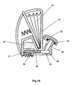
- Fig. 19 illustrates a second embodiment of device for delivering multiple doses of physiologically active agent in powdered form.
- the device is intended to be hand-held and comprises a main body which may advantageously be moulded in plastics material, as may most of the components of the device in this and the other embodiments.
- the main body 31 includes a nasal tube 32 for insertion in the nostril of a patient and defining internally a powder delivery passage.
- a closure 33 in the form of a hinged lid.
- the lid to tube seal may, as shown, be enhanced by the provision of an O-ring 34.
- the closure 33 also has the advantage of preventing debris from entering the device via the powder delivery passage.
- the bulk reservoir 35 containing multiple doses of powder has an aperture or exit 36 provided in its base surface.
- a powder metering slide 37 is positioned below the bulk reservoir 35 and is intended to slide linearly (horizontally as drawn) in a guide channel 38.
- the drug metering slide 37 is provided with a recess in the form of a through aperture 39 which, through sliding movement of the slide 37, can be moved from alignment with the bulk reservoir exit 36 (as shown in Fig. 19) to be aligned, instead, with the powder delivery passage provided in the nasal tube 32.
- the powder metering slide 37 When the powder metering slide 37 is in the position shown in Fig. 19, powder from the bulk reservoir 35 will, under the influence of gravity, enter and fill the aperture 39 provided in the slide 37.
- the aperture 39 may be transported into alignment with the powder delivery passage provided in the nasal tube 32, and with a passage 40 opening out of the base of the channel 38, which passage 40, in use, forms the upstream air supply passage (from the bellows 41).
- the top surface of the slide 37, to the left of the aperture 39 slides underneath the aperture 36 provided in the base of the bulk reservoir 35 to prevent powdered drug from falling out of the reservoir aperture 36 to foul the channel 38.
- the recess 39 formed in the slide forms a cup for metering out the required dose of powder.
- the arrangement for priming and triggering the bellows 41 in the second embodiment may be as in the first embodiment of Figs. 1-14, or may alternatively be as described above in connection with Figs. 15-18.
- the drug metering slide 37 is manually indexed by the user from the position shown to bring its aperture 39 into alignment with the downstream powder delivery passage, prior to the forced flow through the aperture 39 of air from the bellows 41. Once the device has been used to deliver a metered dose of powder, the slide 37 will need to be moved back to the left, to meter out a fresh dose of powder, prior to being moved back to the right, in order for the device to be used to deliver a subsequent dose.
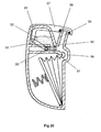
- the third embodiment of device avoids the need to have a separate manual action to index the drug metering slide, by linking this indexing movement with another task which the device user has to perform, namely movement of the closure covering the nasal tube.
- a powder metering slide 50 is provided which is movable linearly from having its powder receiving aperture or recess 51 aligned with the exit 52 from its bulk reservoir 53 to a position (to the right as drawn in Fig. 20) in which the metering slide's aperture 51 is positioned in line with an upstream air supply passage 54 (leading from the bellows exit) and a downstream powder delivery passage 55 formed by the nasal tube 56.
- the main difference between the second and third embodiments resides in the manner in which the powder metering slide 50 is moved between its two main positions.
- the closure 57 which closes the nasal tube 56 when the device is not in use, is attached to the main body of the device at a hinge point 58.
- the closure is, however, additionally connected to the drug metering slide 50 via a linkage 59.
- the linkage 59 acts as a pushrod to slide the powder metering slide 50 to the right, from the position shown in Fig. 20.
- the drug metering slide 50 will have been moved sufficiently far to the right that its aperture 51 will then be coaxially aligned with the upstream air supply passage 54 and the downstream powder delivery passage 55, making the device ready for use.
- the above described third embodiment of device should be simpler to use than the second embodiment of device in that it avoids the need for the device user to consciously index the powder metering slide manually.
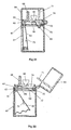
- Figures 21 and 22 illustrate a fourth embodiment of device. This device works on a similar principle to the previous devices.
- the fourth embodiment of device comprises a main element 60 incorporating the powder metering unit.
- a base housing 61 enclosing the bellows 62, seals against the main element 60, this seal being enhanced by the provision of an O-ring seal 63.
- a closure 64 in the form of a hinged cover, is attached to the base housing 61 by a hinge. To enhance sealing of the closure 64 to the main element 60 a further O-ring 65 is provided.
- the powder metering unit includes a metering slide 65.
- the recess provided in the slide for receiving the metered dose of powder comprises a U-shaped cup, opening only into the top face of the slide, such that the forced air flow to dislodge the metered dose of powder both enters and exits the powder-containing recess through the single aperture in the top face of the slide 65.
- the absence of a through hole in the slide 65 eliminates the possibility of particles falling downwardly through a hole in the slide, which is a possibility with the second and third embodiments described above.
- the metering slide 65 is movable between two main positions.
- the first position is one in which the recess in the metering slide can receive powder from the bulk reservoir 66, in which position it is isolated from both the upstream air supply passage 67 and the downstream powder delivery passage 68. This first position is shown in Fig. 21.
- the second main position for the metering slide is shown in Fig. 22.
- the recess in the metering slide is coincident with both the upstream air supply passage 67 and the downstream powder delivery passage 68 and is isolated from the bulk reservoir 66.
- the fourth embodiment it is the action of the powder-containing recess formed in the metering slide moving out of alignment with the powder exit from the bulk reservoir 66 which controls the amount of powder in the metered dose.
- the fourth embodiment is constructed and arranged so that the metering unit is operated by the action of moving the closure 64.
- the metering slide is provided with a flexible linkage 69 which is pivotally attached to a hook 70 at the right hand end of the channel in which the slide moves.
- the flexible linkage 69 is sufficiently stiff and resilient, for example being made of plastics material, that when not acted upon by external influences it will straighten (as shown in Fig. 22), causing the metering slide to move to the aforementioned second position.
- the closure 64 when, prior to using the device to discharge powdered drug, the closure 64 is opened, the metering slide will move automatically from its first position to its second position, to carry a metered dose of powder into alignment with the air supply and powder delivery passages, 67,68. In this condition, the forced flow of gas from the manually rechargeable air reservoir, in the form of bellows 62, will deliver the powder in the manner discussed above.
- moisture can have an adverse effect.
- moisture ingress into the device can adversely affect the delivered dose of agent by coating surfaces and causing agglomeration of the powder.
- the design of the fourth embodiment of device is effective in restricting the unwanted ingress of air (and thus moisture) into the device when the device is not in use.
- closure 64 prevents unwanted ingress of ambient air (and moisture) through the powder delivery passage in the nasal tube, but it also has the effect of sealing the apertures 72,74 such that the maximum amount of moisture that can be present in the device will be that present in the device, and the air trapped in the device, at the time the closure 64 is closed after use.
- closure 64 is shown as being hinged to the remainder of the device, it will be appreciated that the closure 64 could equally well be completely detachable from the remainder of the device, such that to open the closure one removes it from the remainder of the device and replaces it after use.
- the hinged arrangement in Figs. 21 and 22 is preferred because it prevents the closure 64 from being detached and getting lost.
- the powder metering slide 65 moves from its first position to its second position (on opening) and from its second position back to its first position (on closing), other movement possibilities are envisaged.
- the metering slide 65 might start at its second position, move initially to its first position (to receive a metered dose of powder) and then move back to the second position.
- there might be a third position for the metering slide in which the powder-containing recess in the slide is neither capable of receiving powder from the bulk reservoir 66 nor coincident with either of the air supply passage 67 or the powder delivery passage 68, and from which, when the closure 64 is opened, the slide 65 is moved to the first position and then to the second position.
- the metering slide 65 might be moved to its first position by the action of opening the closure, although in this case some means would need to be provided to move the slide subsequently to its second position prior to activation of the device to discharge the powder.
- the bellows 62 may take the form of any of the bellows described above, with regard to charging and/or triggering release of a charge of air.
- priming of the bellows could advantageously be linked to another operation which the user of the device already has to perform.
- priming of the bellows might also be linked to the action of opening or closing the closure 64.
- the bellows 62 might also be primed (i.e.
- triggering of the release of the bellows could also be linked to movement of the closure 64.
- part of the full range of movement of the closure 64 might be used to move the metering slide 65 to its second position and to charge the bellows 62, with the final portion of the closure's range of movement being used to trigger release of the bellows, i.e. to "fire" the device.
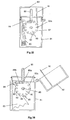
- Figs. 23 and 24 of the application is fundamentally similar to that of the fourth embodiment of Figs. 21 and 22.
- similar parts have been given the same reference numerals as in Figs. 21 and 22.
- the main difference, apart from a slight change in general layout, is in the arrangement of the linkage 69.
- the right hand end of the linkage 69 is attached to the closure 64, rather than to a hook 70 provided at the stationary right hand side of the main element 60. In this way, the need to have a downwardly depending element 71 to displace the linkage 69 laterally can be avoided.
- each of the devices is provided with a powder container defining therein a plurality of individual receptacles, each receptacle containing a discrete metered dose of powder. This avoids the need for a dose of powder to be metered within the device; instead, the doses can be pre-metered in a factory before the powder container is associated with the remainder of the device.
- the device comprises a base housing 81 having an openable closure 82 attached thereto by a hinge.
- a bellows 83 is provided in the base housing and feeds into the upstream end of an upstream air supply passage 84.
- This air supply passage terminates at a downstream end that is aligned with, but spaced apart from, the upstream end of a downstream drug delivery passage 85.
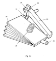
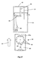
- This spacing is equivalent to the axial thickness of the powder container 80; such that when a removable cassette 86 housing the powder container 80 is slid (in the direction of arrow 87 in Fig. 27) into the open bottom of the base housing 81, a circumferential portion of the rotatable powder container 80 will be snugly received in the gap between the downstream end of the upstream air supply passage 84 and the upstream end of the downstream drug delivery passage 85.
- the powder container 80 is provided in the region of its circumference with twelve receptacles 88 in the form of throughbores. Each of these throughbores 88 is sized to contain a discrete pre-metered dose of powder for delivery.
- the powder container 80 is mounted on a spindle 89 to allow it to be rotatably indexed, as will be described below. In the position shown in Fig. 27, only the open first and second opposite ends of the uppermost throughbore 88a are exposed. The opposite ends of the remaining eleven throughbores are closed by the main walls 90 of the removable cassette 86, only one of these walls 90 being visible in Fig. 27. Consequently, the metered doses of powder contained within these eleven closed throughbores are prevented from leaking out of the throughbores - any leakage would be undesirable as it could lead to underdosing.
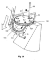
- a flexible indexing finger 91 will move into contact with one of the twelve gear teeth 92 provided around the periphery of the powder container 80.
- the tip of the flexible indexing finger 91 will come into contact with the gear tooth 92a in the 2 o'clock position (as drawn in Fig. 26).
- Continued closing of the closure 82 after this finger-to-tooth contact is established will rotate the powder container 80 through 1/12 of a turn in the clockwise direction, such that the geartooth 92a ends up in the 3 o'clock position, as shown in Fig.
- a pawl 93 is provided to cooperate with the gear teeth 92 of the ratchet-like container 80.
- the powder container 80 as well as the body of the removable cassette 86, the base housing 81 and the closure 82 are injection moulded in an engineering plastics material.
- the cassette 86 can be removed from the device by pulling on the integrally moulded handle 94 and the removed cassette 86 discarded. In its place, an entirely fresh replacement cassette 86 can be inserted, to enable the device to be used for a further twelve dosing events.
- the powder container could be provided with greater or fewer powder-containing receptacles.
- a separate gear wheel can be provided between the flexible indexing finger 91 and the powder container 100.
- a gear wheel 101 is provided with its number of gear teeth matching the number of powder-containing receptacles provided in the powder container 100, this number being six in the illustrated arrangement.
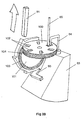
- FIG. 28 and 29 A further difference between the arrangement illustrated in Figs. 28 and 29, and that illustrated in Figs. 25-27, is that in the Fig. 28 and 29 arrangement the powder containing receptacles 102 are not throughbores but are instead cup-shaped. Consequently, only the upper surface of the powder container 100 has openings formed therein and the upstream air supply passage 84 and the downstream drug delivery passage 85 both face into the receptacles 102 (when aligned therewith) through this single, upwardly facing opening.
- a face plate with a small sector cut away around the downstream end of the upstream air supply passage 84 and the upstream end of the downstream drug delivery passage 85 may be placed over the top of the powder container 100 so that only one powder-containing receptacle 102 is open at any given time.
- a foil membrane could be provided over each of the receptacles, which membrane is slit or otherwise ruptured prior to the contents of the respective receptacle being discharged. This would enhance the protection of the doses against degradation from airborne moisture.
- the manually rechargeable air reservoir takes the form of an inflatable bellows provided with a spring bias, with the bellows being expanded against the spring bias to charge the bellows with air
- these means may alternatively take the form of a cylinder and piston arrangement.
- the piston could be provided with a spring bias, with the piston being moved against the spring bias to sweep the cylinder to charge the cylinder with air ready for triggering and air release.
Landscapes
- Health & Medical Sciences (AREA)
- Engineering & Computer Science (AREA)
- Life Sciences & Earth Sciences (AREA)
- Anesthesiology (AREA)
- Pulmonology (AREA)
- Biomedical Technology (AREA)
- Heart & Thoracic Surgery (AREA)
- Hematology (AREA)
- Bioinformatics & Cheminformatics (AREA)
- Animal Behavior & Ethology (AREA)
- General Health & Medical Sciences (AREA)
- Public Health (AREA)
- Veterinary Medicine (AREA)
- Biophysics (AREA)
- Infusion, Injection, And Reservoir Apparatuses (AREA)
- Medical Preparation Storing Or Oral Administration Devices (AREA)
Abstract
Description
- This invention relates to a device for delivering multiple doses of physiologically active agent in powdered form. The device is preferably, but not exclusively, intended for the delivery of a physiologically active agent in powdered form into a patient's nasal cavity.
- The term "physiologically active agent" used hereinafter includes any compound or composition of matter which, when administered to an organism (human or animal subject) induces a desired pharmacologic and/or physiologic effect by local and/or systemic action. The term therefore includes those compounds or chemicals traditionally regarded as drugs, biopharmaceuticals (including molecules such as peptides, proteins, nucleic acids), vaccines and gene therapies (e.g. gene constructs). When the agent is provided in powdered form, the size of the powder is affected by its delivery route. For pulmonary delivery the optimum particle size is 1-5µm, whereas for nasal delivery the optimum size is believed to be 10-20µm. A suitable amount for a single dosing event is of the order of 100's of µg to 10's of mg.
- It has .been recognised that nasal delivery provides an excellent route for delivering some physiologically active agents into the human system in addition to topical treatment. For example, advantages of nasal delivery include high permeability of the nasal cavity compared with the gasto-intestinal tract, the highly vascularised subepithelial layer in the nasal mucosa and high patient compliance compared with injection. This can lead to potentially greater therapeutic effect, the requirement for potentially smaller doses and rapid systemic absorption. There is a demand amongst pharmaceutical companies for nasal drug delivery devices which have some of the following properties: smaller delivery volumes, increased dosing accuracy, an avoidance for a need to prime device, prevention of bacteriological contamination and performance that is independent of the user.
- Dry powders of physiologically active agents generally offer advantages over liquid formulations in nasal delivery, these advantages including longer retention in the nasal cavity, better absorption of some agents, use of higher concentrations of agent, minimisation of problems associated with liquid running back out of the nose and improved stability of the physiologically active agent when stored in dry form.
-
US-A-5 740 792 discloses a dry powder inhaler for delivering multiple doses of physiologically agent in powdered form. The device comprises a rotatable metering dose plate for use in metering out successive single doses of powder from a bulk reservoir of powder provided within the device. A powder delivery passage is provided for the flow therealong to a patient of air with a said metered dose of powder entrained therein so as substantially to empty a metered dose hole provided in the metering dose plate. The device is further provided with a closure for covering the powder delivery passage when the device is not in use. The action of removing the closure moves the metered dose hole from alignment with the bulk reservoir into alignment with the powder delivery passage. When the closure is replaced, the metered dose hole is moved back from alignment with the powder delivery passage into alignment with the bulk reservoir. -
US-A-5 921 237 discloses an inhaler comprising a powder container defining therein a plurality of individual receptacles, each containing a discrete metered dose of a drug; a container indexing mechanism for sequentially presenting each receptacle to the outlet of the inhaler; and a closure for preventing ingress of moisture into the inhaler. The inhaler disclosed inUS-A-5 921 237 is operated by the inhalation action of a patient in combination with a powered impeller. -
WO 94/11044 - Both
US-A-5 921 237 andWO 94/11044 - According to the present invention there is provided a device for delivering multiple doses of physiologically active agent in powdered form, the device comprising:
- a manually rechargeable air reservoir;
- a powder container defining therein a plurality of individual receptacles, each receptacle containing a discrete metered dose of powder,
- a powder delivery passage for the forced flow therealong to a patient of air with a said metered dose of powder entrained therein so as substantially to empty a said receptacle,
- a closure for restricting the unwanted ingress of moisture into the device via said passage when the device is not in use; and
- a container indexing mechanism for indexing movement of said container to move a substantially empty said receptacle out of communication with said powder delivery passage and to move a fresh powder-containing said receptacle into communication with said powder delivery passage;
- In a preferred embodiment of device in accordance with the present invention, the operation of the container indexing mechanism and/or the charging of the air reservoir with air is performed automatically by the operator of the device (usually the intended recipient or patient) opening the closure, which action the operator will have to perform in any event. In removing the need for that person to conduct a conscious, discrete action of operating the powder container indexing mechanism and/or charging the air reservoir with air (separately of the act of opening or closing the closure), use of the device is simplified.
- Embodiments of device will now be described, by way of example only, with reference to the following drawings, described in the paragraph immediately below. Of the illustrated embodiments, only those of Figs.25 - 27 and 28 - 29 are in accordance with the invention as claimed. The embodiments of device illustrated in Figs. 1 - 24 are not in accordance with the invention as claimed.
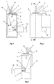
- Fig. 1 is a perspective view of a first embodiment of device for use in delivering multiple doses of physiologically active agent in powdered form;
- Fig. 2 is a vertical cross-section of the Fig. 1 device, taken along the line II II in Fig. 3;
- Fig. 3 is a front elevation of the device of Fig. 1;
- Fig. 4 is a side elevation of the device of Fig. 1;
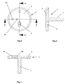
- Fig. 5 is a cross-sectional side elevation, taken along the line V-V in Fig. 6, of the top plate of the embodiment of Fig. 1;
- Fig. 6 is a top plan view of the top plate of the first embodiment;
- Fig. 7 is a cross-sectional side elevation of the spacer plate of the first embodiment, taken along the line VII-VII of Fig. 8;
- Fig. 8 is a top plan view of the spacer plate of the first embodiment;
- Fig. 9 is a cross-sectional side elevation, taken along the line IX-IX of Fig. 8;
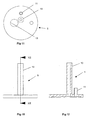
- Fig. 10 is a side elevation of the nozzle plate of the first embodiment;
- Fig. 11 is a top plan view of the nozzle plate of Fig. 10;
- Fig. 12 is a cross-sectional side elevation of the top plate, taken along the line XII-XII of Fig. 10;
- Fig. 13 is a front elevation of the bellows of the first embodiment;
- Fig. 14 is a side elevation of the bellows of Fig. 13;
- Fig. 15 illustrates an alternative triggering mechanism for the bellows of the first embodiment of device;
- Figs. 16-18 illustrate a sequence of operation for the alternative triggering mechanism of Fig. 15;
- Fig. 19 illustrates a second embodiment of device for delivering multiple doses of physiologically active agent in powdered form, in cross-sectional side elevation;
- Fig. 20 illustrates a third embodiment of device for delivering multiple doses of physiologically active agent in powdered form, in cross-sectional side elevation;
- Figs. 21 and 22 illustrate, in cross-sectional side elevation, a fourth embodiment of device for delivering multiple doses of physiologically active agent in powdered form, Fig. 21 showing the device's closure closed and Fig. 22 showing the closure opened;
- Figs. 23 and 24 illustrate, in cross-sectional side elevation, a fifth embodiment of device for delivering multiple doses of physiologically active agent in powdered form, Fig. 23 showing the device's closure closed and Fig. 24 showing the closure opened;
- Figs. 25 and 26 illustrate, in cross-sectional side elevation, a sixth embodiment of device for delivering multiple doses of physiologically active agent in powdered form, Fig. 25 showing the device's closure closed and Fig. 26 showing the closure opened;
- Fig. 27 is a similar view to that of Fig. 25, but showing a cassette housing the powder container removed from the remainder of the sixth embodiment of device; and
- Figs. 28 and 29 are perspective views of a powder containing indexing mechanism suitable for use in a seventh embodiment of device for delivering multiple doses of physiologically active agent in powdered form.
- Figs. 1-14 of the drawings illustrate a bench prototype (and components thereof) of a first embodiment of device suitable for delivering multiple doses of physiologically active agent in powdered form, built to test some of the principles involved. It is anticipated that, as in the later embodiments, the finished device will be capable of being reduced in size to be hand-held in use, and capable of being stored in a pocket or handbag when not in use. Figs 19 onwards illustrate more compact, hand-held devices.
- In the embodiment illustrated in Figs. 1-14, the device comprises a
frame 1 of generally U-shaped cross section - see Figs. 1 and 2. Secured to the top of theframe 1 is atop plate 2 having arecess 3 formed in its top planar surface. Thisrecess 3 is generally cup-shaped and can be seen most clearly in Fig. 5. Thetop plate 2 combines with aspacer plate 4 and anozzle plate 5 to form a powder metering unit for metering out a dose of powder from a bulk reservoir containing multiple doses of powder. - The
spacer plate 4 includes a maincircular element 6 with acylindrical hub 7 downwardly depending therefrom, as shown in Fig. 7. Thecylindrical hub 7 is rotatably received in a bore provided in thetop plate 2, to enable the spacer plate 4 (andnozzle plate 5 mounted thereon) to be rotatably indexed relative to thetop plate 2 around the longitudinal axis of thehub 7, for reasons which will be explained later. - Provided in the main
circular element 6 are twoangled drillings cylindrical hub 7. Spaced 90° therefrom with regard to said longitudinal axis, the maincircular element 6 is also provided with anaperture 9 which converges downwardly in the manner of a hopper. - The
nozzle plate 5 is mounted on top of theplate 4 and is rotationally fast therewith. Thespace plate 4 andnozzle plate 5 were made separately in the embodiment of Figs. 1-14 purely for ease of manufacture. Thenozzle plate 5 has twostub pipes cylindrical hub 7 of thespacer plate 4. The longest stub pipe models a nasal tube for insertion into the nostril of a patient. Theshorter stub tube 11 is intended to have the end of a flexible tube fitted thereover (shown only in dotted lines 16), the flexible tube leading from the output of a manuallyrechargeable air reservoir 12 which will be described later. - The flat surface of the
nozzle plate 5 is also provided with anaperture 13. When thenozzle plate 5 andspacer plate 4 are assembled together, thisaperture 13 is positioned over, and in alignment with, theaperture 9 provided in thespacer plate 4, as shown in Fig. 1, to form the base of a bulk reservoir for powder. Thenasal tube 10 is positioned over, and in alignment with,drilling 8b of thespacer plate 4. Thestub tube 11 is positioned over, and in alignment with, the upper end of thedrilling 8a. As can be seen from Fig. 2 of the application, when the (rotationally fast) assembly of thespacer plate 4 andnozzle plate 5 is rotated around the axis of thecylindrical hub 7, such that theangled drillings recess 3 provided in thetop plate 2, a continuous passage, suitable for the flow therethrough of gas, is established. This passage (as one travels in the downstream direction) constitutes the bore ofstub pipe 11, the bore ofangled drilling 8a, the generally cup-shaped interior ofrecess 3, the bore ofangled drilling 8b and finally the bore ofnozzle tube 10. By rotating the assembly of the spacer plate andnozzle plate 5, around the longitudinal axis ofcylindrical hub 7, in a clockwise direction from the position shown in Figs. 1-4, thedrillings recess 3. Instead, the base of the bulk reservoir constituted by alignedapertures recess 3. - By starting with the assembly of the
nozzle plate 5 andspacer plate 4 in the position shown in Figs. 1-4, if the bulk drug reservoir formed by the alignedapertures assembly recess 3 the powder in the reservoir will no longer be supported by the upper face of thetop plate 2, such that powder will fall into therecess 3 to fill it. By then indexing theassembly recess 3 and the powder in thereceptacle 3 is scribed off flat by the edge at the base ofaperture 9, to leave therecess 3 filled with a volume of powder equal to the internal volume of therecess 3. This volume of powder is known as a metered dose and by varying the volume of therecess 3 the size of the metered dose can obviously be changed. Because the bases of theangled drillings recess 3, it will be apparent that if gas is blown vigorously down an upstream gas supply passage formed by the aligned bores ofstub pipe 11 anddrilling 8a, the metered dose of powder in therecess 3 will be displaced from therecess 3 and entrained in the gas as the gas passes along a downstream powder delivery passage constituted by the bores ofdrilling 8b andnasal tube 10. - Once the metered dose has been delivered from the device in the manner described above, by repeating the process of indexing the assembly of the
nozzle plate 5 andspacer plate 4 by rotating it through 90° clockwise and then re-indexing it through 90° anti-clockwise, it will be apparent that a fresh dose of powder from the bulk reservoir can be metered in therecess 3 so as to enable the device to be used to deliver a second dose, thus enabling the device to be used to deliver multiple sequential metered doses. - As will become apparent from the later embodiments, the bulk reservoir is likely to be both larger and sealed. In the bench prototype of the embodiment of Figs. 1-14, the bulk reservoir formed by aligned
apertures - It will be apparent from the above that the powder metering unit formed by the
top plate 2,spacer plate 4 andnozzle plate 5 can be used to meter accurately metered doses of powder from a bulk reservoir containing sufficient loose powder to make up multiple doses of powder. - In this first embodiment, all of the
frame 1,top plate 2,spacer plate 4 andnozzle plate 5 are made of metal, for example steel or aluminium. In commercial embodiments it is anticipated that as many of these parts as possible will be made in plastics material, for reasons of both economy and light weight, such a material being well suited to moulding. - In the embodiment of Figs. 1-14, the forced flow of gas used to discharge the metered dose of powder from the
nasal tube 10 is provided by a manuallyrechargeable air reservoir 12 in the form of a bellows. The bellows is expandable and contractible as denoted by the double-headedarrow 13 in Fig. 2. The bellows is provided with a one way valve on its body, as indicated schematically at 14, as is theair exit 15 from the bellows. Consequently, in expanding the bellows, air enters the bellows via one way valve 14 (and not via bellows exit 15), whereas upon compression of the bellows air is forced from the bellows exit 15 (and not from valve 14). - For reasons of clarity, the flexible pipe 16 which would link the bellows exit 15 to the
stub pipe 11 on thenozzle plate 5 has been represented schematically by a pair of dotted lines. The purpose of this flexible pipe is to channel the forced flow of air from thebellows 12 into the bore of thestub pipe 11, for use in entraining and discharging a metered dose of powder. - The bellows 12 is expanded against the restoring bias of a
compression spring 17. In the Fig. 1-14 embodiment, the bias of this spring can be modified by changing the position of aplunger 18, relative to a sidewall of theframe 1, but this is not envisaged as being necessary in a commercial device. Once thebellows 12 has been expanded and air drawn into the bellows via the oneway valve 14, a part of thespring post 19 provided at the left hand end of compression spring 17 (as drawn in Fig. 2) slides under the end of aresilient spring latch 20. In the condition illustrated in Fig. 2, thebellows 12 is in an expanded position, with thespring 17 compressed, i.e. the air reservoir is primed. Consequently, when the left hand end of thespring latch 20 is raised; thespring post 19 is no longer restrained by thespring latch 20, enabling the restoring force of thespring 17 to contract thebellows 12, forcing air out of thebellows exit 15, along the interior of flexible pipe 16, into the bore ofstub pipe 11, enabling a metered dose of powder in therecess 3 to be entrained in the air and discharged from thenozzle tube 10. - It will be noted that the
bellows 12 is not manually compressed by the user of the device; it is manually expanded. If the bellows were to be manually compressed, the velocity of the gas exiting the bellows exit 15 would be dependent upon the rate of compression of thebellows 12 by the user. Because the rate of gas exit from the bellows exit 15 can influence the way in which the powder of the metered dose is entrained and discharged, it is advantageous to be able to remove this variable from influence by the device user. Consequently, in the illustrated embodiment it is advantageous that all the user has to do, once thebellows 12 is primed (as shown in Fig. 2), is to trigger compression of thebellows 12 by raising thespring latch 20. The rate of compression of thebellows 12 is then determined by the bias of thespring 17. - Figs. 15-18 illustrate an alternative triggering mechanism for a bellows. For reasons of clarity the surroundings to the mechanism are omitted. For example, it will be appreciated that in this arrangement, the
spring 20 used to compress thebellows 21 will need to be braced against some other part of the device. - In the Fig. 15-18 arrangement, an operating
lever 22 is provided. At one end of the operatinglever 22 the lever is hinged adjacent thebellows air exit 23. At the other end alatch 23 is pivotally attached to thelever 22. Upon lifting the latch end of thelever 22, engagement of thelatch 23 with apin 24 provided on one of the side walls of thebellows 21 causes the bellows to be expanded, as shown in Figs. 15 and 16. When the bellows 21 have been fully recharged with air, thelatch 23 engages the underside of astop peg 25, such that continued lifting movement of thelever 22 causes thestop peg 25 to pivot thelatch 23 around its point of attachment to thelever 22, moving the hook provided at the base of thelatch 23 free from engagement with the pin 24 (as shown in Fig. 17). This enables thespring 20 to compress the bellows (as shown in Fig. 18) to force air out of thebellows exit 23. In this arrangement it will be appreciated that the bellows may be recharged with air, and then have its release triggered, all using one lever. For example, in the case of the device being used to deliver powder to the nasal cavity of a patient, once the nasal tube is inserted in the patient's nostril the patient could in one simple movement of thelever 22 both recharge the bellows with air and then release that charge of air, avoiding the need to have one lever or control for priming the rechargeable air reservoir and another control element for triggering release of air from the primed air reservoir. - Fig. 19 illustrates a second embodiment of device for delivering multiple doses of physiologically active agent in powdered form. The device is intended to be hand-held and comprises a main body which may advantageously be moulded in plastics material, as may most of the components of the device in this and the other embodiments.
- In the second embodiment the
main body 31 includes anasal tube 32 for insertion in the nostril of a patient and defining internally a powder delivery passage. To restrict the unwanted ingress of airborne moisture into the device through the powder delivery passage, the distal or downstream end of thenasal tube 32 is provided with aclosure 33 in the form of a hinged lid. The lid to tube seal may, as shown, be enhanced by the provision of an O-ring 34. In addition to inhibiting the inflow of moisture into the device, which could adversely affect the powdered agent, theclosure 33 also has the advantage of preventing debris from entering the device via the powder delivery passage. - In the second embodiment the
bulk reservoir 35 containing multiple doses of powder has an aperture orexit 36 provided in its base surface. Apowder metering slide 37 is positioned below thebulk reservoir 35 and is intended to slide linearly (horizontally as drawn) in aguide channel 38. Thedrug metering slide 37 is provided with a recess in the form of a throughaperture 39 which, through sliding movement of theslide 37, can be moved from alignment with the bulk reservoir exit 36 (as shown in Fig. 19) to be aligned, instead, with the powder delivery passage provided in thenasal tube 32. When thepowder metering slide 37 is in the position shown in Fig. 19, powder from thebulk reservoir 35 will, under the influence of gravity, enter and fill theaperture 39 provided in theslide 37. The bottom interior surface of theguide channel 38 will fit closely against the bottom surface of theslide 37, such that powder will not fall out of the bottom of theaperture 39. By then moving theslide 37 to the right (as drawn) theaperture 39 may be transported into alignment with the powder delivery passage provided in thenasal tube 32, and with apassage 40 opening out of the base of thechannel 38, whichpassage 40, in use, forms the upstream air supply passage (from the bellows 41). In moving to the right (from the position shown in Fig. 19), the top surface of theslide 37, to the left of theaperture 39, slides underneath theaperture 36 provided in the base of thebulk reservoir 35 to prevent powdered drug from falling out of thereservoir aperture 36 to foul thechannel 38. It will be appreciated that therecess 39 formed in the slide forms a cup for metering out the required dose of powder. - Once the metered dose in the
aperture 39 of theslide 37 has been moved into alignment with the downstream powder delivery passage, it will be appreciated that, by operating thebellows 41 to discharge therefrom a charge of air, the forced flow of air from thebellows 41 to the upstream air supply passage 40 (only the downstream end of which is visible in Fig. 19) will displace the metered dose of powder from theaperture 39 and entrain it in the forced air flow prior to exiting from the distal end of thenasal tube 32 past the openedclosure 33. - The arrangement for priming and triggering the
bellows 41 in the second embodiment may be as in the first embodiment of Figs. 1-14, or may alternatively be as described above in connection with Figs. 15-18. - In the second embodiment the
drug metering slide 37 is manually indexed by the user from the position shown to bring itsaperture 39 into alignment with the downstream powder delivery passage, prior to the forced flow through theaperture 39 of air from thebellows 41. Once the device has been used to deliver a metered dose of powder, theslide 37 will need to be moved back to the left, to meter out a fresh dose of powder, prior to being moved back to the right, in order for the device to be used to deliver a subsequent dose. - The third embodiment of device, described below in conjunction with Fig. 20, avoids the need to have a separate manual action to index the drug metering slide, by linking this indexing movement with another task which the device user has to perform, namely movement of the closure covering the nasal tube.
- In the third embodiment of device, illustrated in Fig. 20, although the layout of the main components (bulk reservoir, bellows and nasal tube) is different from that in the second embodiment (see Fig. 19), the principle of operation of the device is fundamentally similar in that a
powder metering slide 50 is provided which is movable linearly from having its powder receiving aperture orrecess 51 aligned with theexit 52 from itsbulk reservoir 53 to a position (to the right as drawn in Fig. 20) in which the metering slide'saperture 51 is positioned in line with an upstream air supply passage 54 (leading from the bellows exit) and a downstreampowder delivery passage 55 formed by thenasal tube 56. - The main difference between the second and third embodiments resides in the manner in which the
powder metering slide 50 is moved between its two main positions. As can be seen, theclosure 57, which closes thenasal tube 56 when the device is not in use, is attached to the main body of the device at ahinge point 58. The closure is, however, additionally connected to thedrug metering slide 50 via alinkage 59. As theclosure 57 is opened prior to using the device; in pivoting anti-clockwise (as drawn) around itshinge point 58, thelinkage 59 acts as a pushrod to slide thepowder metering slide 50 to the right, from the position shown in Fig. 20. When theclosure 57 is fully opened, thedrug metering slide 50 will have been moved sufficiently far to the right that itsaperture 51 will then be coaxially aligned with the upstreamair supply passage 54 and the downstreampowder delivery passage 55, making the device ready for use. - Once the device is readied for use in this way, a charge of gas can be released from the bellows. The forced flow of air up the upstream
air supply passage 54 will displace the metered dose of powder from theaperture 51 in thedrug metering slide 50 and the powder, entrained in the air flow, will exit the device via the downstreampowder delivery passage 55. If, when the device is used, the distal end of the nasal tube has been inserted into the nostril of a patient, it will be appreciated that in this way the metered dose of powder can be delivered to the nasal cavity of the patient. In the Fig. 20 device, the arrangement and operation of the bellows may be as described in conjunction with any of the earlier Figures. - It will be appreciated that the above described third embodiment of device should be simpler to use than the second embodiment of device in that it avoids the need for the device user to consciously index the powder metering slide manually. By linking the indexing movement of the metering slide with a task which the user cannot avoid performing prior to using the device, namely opening the closure, the number of discrete tasks which the device user has knowingly to perform prior to using the device is reduced.
- It will be noted that the embodiments described so far, and the subsequent embodiment, all rely on the forced flow of gas, from upstream of the metered dose, to displace and entrain the powder. The patient is not required to inhale, although inhalation can be taking place at the moment of powder release. This applies whether the device is used to deliver powder to the nasal cavity of a patient or is used in pulmonary powder delivery via the patient's mouth. In this way, another potential variable is eliminated. In the case of a nasal powder delivery device, different patients can "sniff' with different levels of vigour, affecting the efficiency of powder/air entrainment and powder delivery. Additionally, if a patient has a cold, or is otherwise suffering from a stuffy nose, making it difficult to inhale through the nose, in the absence of a forced gas delivery from within the device, the power of the powder delivery would risk being adversely affected.
- Figures 21 and 22 illustrate a fourth embodiment of device. This device works on a similar principle to the previous devices.
- The fourth embodiment of device comprises a
main element 60 incorporating the powder metering unit. Abase housing 61, enclosing thebellows 62, seals against themain element 60, this seal being enhanced by the provision of an O-ring seal 63. Aclosure 64, in the form of a hinged cover, is attached to thebase housing 61 by a hinge. To enhance sealing of theclosure 64 to the main element 60 a further O-ring 65 is provided. - In common with the second and third embodiments, in the fourth embodiment the powder metering unit includes a
metering slide 65. Unlike in the second and third embodiments, the recess provided in the slide for receiving the metered dose of powder comprises a U-shaped cup, opening only into the top face of the slide, such that the forced air flow to dislodge the metered dose of powder both enters and exits the powder-containing recess through the single aperture in the top face of theslide 65. The absence of a through hole in theslide 65 eliminates the possibility of particles falling downwardly through a hole in the slide, which is a possibility with the second and third embodiments described above. - As in the second and third embodiments, the
metering slide 65 is movable between two main positions. - The first position is one in which the recess in the metering slide can receive powder from the
bulk reservoir 66, in which position it is isolated from both the upstreamair supply passage 67 and the downstreampowder delivery passage 68. This first position is shown in Fig. 21. - The second main position for the metering slide is shown in Fig. 22. In the second position, displaced from the first position, the recess in the metering slide is coincident with both the upstream
air supply passage 67 and the downstreampowder delivery passage 68 and is isolated from thebulk reservoir 66. In common with the second and third embodiments, in the fourth embodiment it is the action of the powder-containing recess formed in the metering slide moving out of alignment with the powder exit from thebulk reservoir 66 which controls the amount of powder in the metered dose. - As in the third embodiment, the fourth embodiment is constructed and arranged so that the metering unit is operated by the action of moving the
closure 64. In the fourth embodiment of Figs. 21 and 22, the metering slide is provided with aflexible linkage 69 which is pivotally attached to ahook 70 at the right hand end of the channel in which the slide moves. Theflexible linkage 69 is sufficiently stiff and resilient, for example being made of plastics material, that when not acted upon by external influences it will straighten (as shown in Fig. 22), causing the metering slide to move to the aforementioned second position. When theclosure 64 is closed, a downwardly dependingelement 71 contacts theflexible linkage 69 to deflect it laterally throughaperture 72, drawing themetering slide 65 to the right, such that when theclosure 64 is fully closed theslide 65 is in the aforementioned first position. - It will thus be appreciated that when, prior to using the device to discharge powdered drug, the
closure 64 is opened, the metering slide will move automatically from its first position to its second position, to carry a metered dose of powder into alignment with the air supply and powder delivery passages, 67,68. In this condition, the forced flow of gas from the manually rechargeable air reservoir, in the form ofbellows 62, will deliver the powder in the manner discussed above. - Once the charge of air has been released from the
bellows 62 to discharge the metered dose of powder from the recess of theslide 65 to the nostril of a patient via the downstreampowder delivery passage 68, the action of the patient closing theclosure 64 will cause theslide 65 to be moved back from its second position to its first position to receive a fresh metered dose of powder. This fresh metered dose will stay in the recess of theslide 65 until such time as the device is next required to be used to discharge a metered dose of powder, whereupon re-opening of theclosure 64 will cause the above train of events to commence again. - With many powdered physiologically active agents, moisture can have an adverse effect. For example, moisture ingress into the device can adversely affect the delivered dose of agent by coating surfaces and causing agglomeration of the powder. The design of the fourth embodiment of device is effective in restricting the unwanted ingress of air (and thus moisture) into the device when the device is not in use.
- In order for the
bellows 62 to be able to intake air through oneway valve 73 upon recharging of the air reservoir, air must be capable of entering thebase housing 61 when the bellows are being expanded. In the fourth embodiment of the device, when theclosure 64 is opened, air can enter thebase housing 61 through the above-mentionedaperture 72 and a further alignedaperture 74 provided in themain element 60. This entry of air is denoted by the arrow 75 in Fig. 22. When the device is not being used, theclosure 64 is closed (as in Fig. 21). Not only does theclosure 64 prevent the unwanted ingress of ambient air (and moisture) through the powder delivery passage in the nasal tube, but it also has the effect of sealing theapertures closure 64 is closed after use. - Although the
closure 64 is shown as being hinged to the remainder of the device, it will be appreciated that theclosure 64 could equally well be completely detachable from the remainder of the device, such that to open the closure one removes it from the remainder of the device and replaces it after use. The hinged arrangement in Figs. 21 and 22 is preferred because it prevents theclosure 64 from being detached and getting lost. - Although, in one cycle of opening and closing the
closure 64, thepowder metering slide 65 moves from its first position to its second position (on opening) and from its second position back to its first position (on closing), other movement possibilities are envisaged. For example, upon opening the closure, themetering slide 65 might start at its second position, move initially to its first position (to receive a metered dose of powder) and then move back to the second position. Alternatively, there might be a third position for the metering slide, in which the powder-containing recess in the slide is neither capable of receiving powder from thebulk reservoir 66 nor coincident with either of theair supply passage 67 or thepowder delivery passage 68, and from which, when theclosure 64 is opened, theslide 65 is moved to the first position and then to the second position. - In a yet further variation, the
metering slide 65 might be moved to its first position by the action of opening the closure, although in this case some means would need to be provided to move the slide subsequently to its second position prior to activation of the device to discharge the powder. - In the device illustrated in Figs. 21 and 22, the
bellows 62 may take the form of any of the bellows described above, with regard to charging and/or triggering release of a charge of air. Alternatively, rather than having a mechanism for priming thebellows 62, requiring a dedicated priming action to be performed by the user, priming of the bellows could advantageously be linked to another operation which the user of the device already has to perform. For example, priming of the bellows might also be linked to the action of opening or closing theclosure 64. Although no such mechanism for this is shown in Figs. 21 and 22, in a manner similar to that in which themetering slide 65 is indexed by opening and closing theclosure 64, thebellows 62 might also be primed (i.e. expanded to recharge with air) upon opening or closing theclosure 64. As an example, one could utilise the action of opening theclosure 64 both to move themetering slide 65 from its first position to its second position and to expand the bellows. Whilst a separate trigger could be provided for triggering release of the primed bellows when the patient wishes to use the device to discharge powder, in a further refinement of the above-mentioned idea triggering of the release of the bellows could also be linked to movement of theclosure 64. For example, part of the full range of movement of theclosure 64 might be used to move themetering slide 65 to its second position and to charge thebellows 62, with the final portion of the closure's range of movement being used to trigger release of the bellows, i.e. to "fire" the device. - The fifth embodiment illustrated in Figs. 23 and 24 of the application is fundamentally similar to that of the fourth embodiment of Figs. 21 and 22. In Figs. 23 and 24 similar parts have been given the same reference numerals as in Figs. 21 and 22. The main difference, apart from a slight change in general layout, is in the arrangement of the
linkage 69. - In the fifth embodiment of Figs. 23 and 24, the right hand end of the
linkage 69 is attached to theclosure 64, rather than to ahook 70 provided at the stationary right hand side of themain element 60. In this way, the need to have a downwardly dependingelement 71 to displace thelinkage 69 laterally can be avoided. - The sixth and seventh embodiments of device illustrated in Figs. 25-29 of the application are fundamentally different to the earlier embodiments in that they do not employ a bulk reservoir for containing multiple doses of powder and do not meter out doses of powder from that bulk reservoir within the device. Instead, each of the devices is provided with a powder container defining therein a plurality of individual receptacles, each receptacle containing a discrete metered dose of powder. This avoids the need for a dose of powder to be metered within the device; instead, the doses can be pre-metered in a factory before the powder container is associated with the remainder of the device.
- In the sixth embodiment of device illustrated in Figs. 25-27, the device comprises a
base housing 81 having anopenable closure 82 attached thereto by a hinge. - A bellows 83 is provided in the base housing and feeds into the upstream end of an upstream
air supply passage 84. This air supply passage terminates at a downstream end that is aligned with, but spaced apart from, the upstream end of a downstreamdrug delivery passage 85. This spacing is equivalent to the axial thickness of thepowder container 80; such that when aremovable cassette 86 housing thepowder container 80 is slid (in the direction ofarrow 87 in Fig. 27) into the open bottom of thebase housing 81, a circumferential portion of therotatable powder container 80 will be snugly received in the gap between the downstream end of the upstreamair supply passage 84 and the upstream end of the downstreamdrug delivery passage 85. - It should be noted that, for reasons of clarity, the structure of the
removable cassette 86 has been omitted from Figs. 25 and 26, although thepowder container 80 has been shown in Figs. 25 and 26. - The
powder container 80 is provided in the region of its circumference with twelvereceptacles 88 in the form of throughbores. Each of thesethroughbores 88 is sized to contain a discrete pre-metered dose of powder for delivery. Thepowder container 80 is mounted on aspindle 89 to allow it to be rotatably indexed, as will be described below. In the position shown in Fig. 27, only the open first and second opposite ends of theuppermost throughbore 88a are exposed. The opposite ends of the remaining eleven throughbores are closed by themain walls 90 of theremovable cassette 86, only one of thesewalls 90 being visible in Fig. 27. Consequently, the metered doses of powder contained within these eleven closed throughbores are prevented from leaking out of the throughbores - any leakage would be undesirable as it could lead to underdosing. - It will be appreciated that when the
removable cassette 86 is slid fully into position in the direction ofarrow 87, theuppermost throughbore 88a will become axially aligned with the downstream end of the upstreamair supply passage 84 and the upstream end of the downstreamdrug delivery passage 85. Consequently, when the bellows 83 is released from the condition shown in Fig. 26, a charge of air will be forced through the upstreamair supply passage 84 to displace the dose of powder from the alignedreceptacle 88a and the resultant displaced powder will be entrained in that air and expelled from the downstream end of the downstreamdrug delivery passage 85. - Following such a dosing event, it is anticipated that the
closure 82 will be hinged shut (from the Fig. 26 position) to attain the position shown in Fig. 25. In being hinged shut, aflexible indexing finger 91 will move into contact with one of the twelvegear teeth 92 provided around the periphery of thepowder container 80. In particular, the tip of theflexible indexing finger 91 will come into contact with thegear tooth 92a in the 2 o'clock position (as drawn in Fig. 26). Continued closing of theclosure 82 after this finger-to-tooth contact is established will rotate thepowder container 80 through 1/12 of a turn in the clockwise direction, such that thegeartooth 92a ends up in the 3 o'clock position, as shown in Fig. 25, and will flex thefinger 91 slightly sideways. In so doing, it will be appreciated that the throughhole 88b which was previously in the 11 o'clock position as drawn in Fig. 26 will be rotated into the position, between the upstreamair supply passage 84 and the downstreamdrug delivery passage 85, previously occupied bythroughhole 88a. In this way, the receptacle empty of powder (throughhole 88a) will be moved out of communication with thepassages passages closure 82 is next opened in preparation for a dosing event a fresh dose of powder will be capable of being discharged. - To prevent unwanted rotational movement of the
powder container 80 in the removable cassette 86 apawl 93 is provided to cooperate with thegear teeth 92 of the ratchet-like container 80. - The mechanisms for priming the
bellows 83 and triggering "firing" of thebellows 83 in the sixth embodiment has been omitted so as to improve clarity; these could be as in one of the previously described embodiments. - Advantageously, the
powder container 80, as well as the body of theremovable cassette 86, thebase housing 81 and theclosure 82 are injection moulded in an engineering plastics material. - Once twelve dosing events have taken place, all of the individual powder-containing
receptacles 88 in thepowder container 80 will have become exhausted. In this situation, thecassette 86 can be removed from the device by pulling on the integrally moulded handle 94 and the removedcassette 86 discarded. In its place, an entirelyfresh replacement cassette 86 can be inserted, to enable the device to be used for a further twelve dosing events. - It will be appreciated that the powder container could be provided with greater or fewer powder-containing receptacles.
- Although in Figs. 25-27 the
powder container 80 is acted on directly by theflexible indexing finger 91, this need not be so. For example, as shown in Figs. 28 and 29, a separate gear wheel can be provided between theflexible indexing finger 91 and thepowder container 100. In the Fig. 28 and 29 arrangement, agear wheel 101 is provided with its number of gear teeth matching the number of powder-containing receptacles provided in thepowder container 100, this number being six in the illustrated arrangement. By providing one face of thegearwheel 101 with a circular track ofteeth 103, which teeth are meshed withteeth 104 provided around the periphery of thepowder container 100, rotational movement of thegearwheel 101 in the vertical plane can be translated into rotational movement of thedrug container 100 in the horizontal plane. - A further difference between the arrangement illustrated in Figs. 28 and 29, and that illustrated in Figs. 25-27, is that in the Fig. 28 and 29 arrangement the
powder containing receptacles 102 are not throughbores but are instead cup-shaped. Consequently, only the upper surface of thepowder container 100 has openings formed therein and the upstreamair supply passage 84 and the downstreamdrug delivery passage 85 both face into the receptacles 102 (when aligned therewith) through this single, upwardly facing opening. - In Figs. 28 and 29, many items have been omitted so as to improve clarity. As in the Fig. 25-27 arrangement, a face plate with a small sector cut away around the downstream end of the upstream
air supply passage 84 and the upstream end of the downstreamdrug delivery passage 85 may be placed over the top of thepowder container 100 so that only one powder-containingreceptacle 102 is open at any given time. - In the arrangement illustrated in Figs. 25-29, a foil membrane could be provided over each of the receptacles, which membrane is slit or otherwise ruptured prior to the contents of the respective receptacle being discharged. This would enhance the protection of the doses against degradation from airborne moisture.
- In the above described different embodiments, except where features present in one embodiment are incompatible with another embodiment, those features may be interchanged. Consequently, when a feature is described in conjunction with one embodiment, for example using the action of opening or closing a closure to recharge the manually rechargeable air reservoir, this facility is applicable to all of the embodiments. Similarly, except where incompatible, the feature or features of each claim should be considered as being disclosed herein as suitable for use in conjunction with the feature or features of every other claim.
- Although in the illustrated embodiments the manually rechargeable air reservoir takes the form of an inflatable bellows provided with a spring bias, with the bellows being expanded against the spring bias to charge the bellows with air, these means may alternatively take the form of a cylinder and piston arrangement. In such an arrangement the piston could be provided with a spring bias, with the piston being moved against the spring bias to sweep the cylinder to charge the cylinder with air ready for triggering and air release.
Claims (26)
- A device for delivering multiple doses of physiologically active agent in powdered form, the device comprising:a manually rechargeable air reservoir (83);a powder container (80, 100) defining therein a plurality of individual receptacles (88, 88a, 88b, 102), each receptacle containing a discrete metered dose of powder,a powder delivery passage (85) for the forced flow therealong to a patient of air with a said metered dose of powder entrained therein so as substantially to empty a said receptacle,a closure (82) for restricting the unwanted ingress of moisture into the device via said passage when the device is not in use; anda container indexing mechanism (91, 92) for indexing movement of said container to move a substantially empty said receptacle (88a) out of communication with said powder delivery passage and to move a fresh powder-containing said receptacle (88b) into communication with said powder delivery passage;wherein the device is constructed and arranged so that the action of opening or closing said closure (i) operates said container indexing mechanism and (ii) charges the air reservoir with air.
- A device as claimed in claim 1, wherein said container indexing mechanism (91, 92) is arranged to perform a said indexing movement upon the action of opening said closure (82) in preparation for using the device for powder delivery.
- A device as claimed in claim 1 or claim 2, wherein the powder container (80) is arranged to revolve around an axis (89) when a said indexing movement is performed.
- A device as claimed in any one of the preceding claims, further comprising an air supply passage (84) for the forced flow therealong of air from the air reservoir (83) wherein, when a said receptacle (88, 102) is in communication with with said powder delivery passage (85), that same said receptacle is also in communication with said air supply passage, whereby said forced flow of air along said air supply passage can be used to dislodge the discrete metered dose of powder from the said receptacle and to entrain said dislodged powder in said air for delivery of the entrained powder to the patient via said powder delivery passage.
- A device as claimed in claim 4, wherein each receptacle (102) provided in said powder container is generally cup-shaped and has a single opening, wherein each receptacle is arranged to communicate with said air supply passage and said powder delivery passage via its said single opening.
- A device as claimed in claim 4, wherein each receptacle provided in said powder container (80) is a throughbore (88) having open first and second opposite ends, wherein each reservoir is arranged to communicate with said air supply passage (84) and said powder delivery passage (85) via its first and second ends respectively, such that in use the forced flow of air passes generally longitudinally through the throughbore.
- A device as claimed in any one of the preceding claims, wherein the container indexing mechanism comprises an indexing element (91) arranged to move upon opening or closing of said closure (82), which element is arranged to index movement of said powder container (80).
- A device as claimed in claim 7, wherein the indexing element (91) is arranged to act directly on the powder container (80) to cause said indexing movement.
- A device as claimed in claim 8, wherein the indexing element comprises a flexible indexing finger (91), which finger is arranged to contact the periphery of the powder container (80) to cause said indexing movement.
- A device as claimed in claim 8, wherein the indexing element (91) is arranged to act indirectly on the powder container (100) to cause said indexing movement.
- A device as claimed in claim 10, wherein the indexing element comprises a flexible indexing finger (91), which finger is arranged to act on a gear wheel (101) separate from and meshed with the powder container (100).
- A device as claimed in claim 9 or claim 11, wherein the tip of the flexible indexing finger (91) is arranged to contact and push on a gear tooth (92)to convert generally longitudinal motion of the flexible indexing finger into generally rotational movement of said powder container (80).
- A device as claimed in claim 12, wherein said gear teeth (92) resemble a ratchet, and a pawl (93) is provided to inhibit unwanted movement of said ratchet.
- A device as claimed in any one of the preceding claims, wherein the air reservoir (83) is constructed and arranged to be freshly charged with air by the action of opening said closure (82) in preparation for using the device for powder delivery.
- A device as claimed in any one of the preceding claims, further comprising a linkage between the reservoir and the closure.
- A device as claimed in claim 15, wherein the closure is pivotable between its open and closed positions and said linkage is arranged to convert at least part of the pivoting movement of the closure into movement of part of the reservoir to cause air to be aspirated into the reservoir to recharge it.
- A device as claimed in any one of the preceding claims, wherein the reservoir comprises a cylinder with a piston slidably and sealably received therein.
- A device as claimed in any one of claims 1 to 16, wherein the reservoir is a bellows (83).
- A device as claimed in claim 17 or claim 18, wherein the piston or bellows (83) is displacable, against a spring bias, from a discharged reservoir condition to a charged reservoir condition so as to recharge the reservoir with air.
- A device as claimed in claim 19, wherein a latching arrangement is provided to latch the piston or bellows in said charged condition.
- A device as claimed in claim 20, wherein the latching arrangement is releaseable to enable the piston or bellows to change from its charged condition to its discharged condition under the influence of said spring bias.
- A device as claimed in claim 20 or claim 21, wherein the latching arrangement is provided with a manually operable trigger to release it.
- A device as claimed in any one of claims 20 to 22, wherein the latching arrangement is arranged to be released by movement of said closure.
- A device as claimed in any one of the preceding claims, wherein the physiologically active agent in powdered form is a compound or composition of matter which, when administered to an organism, induces a desired pharmacologic and/or physiologic effect by local and/or systemic action.
- A device as claimed in any one of the preceding claims, wherein the physiologically active agent in powdered form is a drug, biopharmaceutical, vaccine or gene therapy.
- A device as claimed in any one of the preceding claims, wherein the device is constructed and arranged to be used for delivering multiple doses of physiologically active agent in powdered form into the nasal cavity of a subject.
Applications Claiming Priority (3)
| Application Number | Priority Date | Filing Date | Title |
|---|---|---|---|
| GB0019715 | 2000-08-10 | ||
| GBGB0019715.2A GB0019715D0 (en) | 2000-08-10 | 2000-08-10 | Device for delivering physiologically active agent in powdered form |
| PCT/GB2001/003555 WO2002011800A2 (en) | 2000-08-10 | 2001-08-08 | Device for delivering physiologically active agent in powdered form |
Publications (2)
| Publication Number | Publication Date |
|---|---|
| EP1322356A1 EP1322356A1 (en) | 2003-07-02 |
| EP1322356B1 true EP1322356B1 (en) | 2007-12-05 |
Family
ID=9897388
Family Applications (1)
| Application Number | Title | Priority Date | Filing Date |
|---|---|---|---|
| EP01954194A Expired - Lifetime EP1322356B1 (en) | 2000-08-10 | 2001-08-08 | Device for delivering physiologically active agent in powdered form |
Country Status (9)
| Country | Link |
|---|---|
| US (1) | US7275537B2 (en) |
| EP (1) | EP1322356B1 (en) |
| JP (1) | JP2004509669A (en) |
| AU (2) | AU2001276538B2 (en) |
| CA (1) | CA2418906A1 (en) |
| DE (1) | DE60131760T2 (en) |
| ES (1) | ES2295187T3 (en) |
| GB (1) | GB0019715D0 (en) |
| WO (1) | WO2002011800A2 (en) |
Cited By (1)
| Publication number | Priority date | Publication date | Assignee | Title |
|---|---|---|---|---|
| US11154665B2 (en) | 2015-06-24 | 2021-10-26 | Ethicon, Inc. | Hemostatic powder delivery devices and methods |
Families Citing this family (26)
| Publication number | Priority date | Publication date | Assignee | Title |
|---|---|---|---|---|
| US6082358A (en) | 1998-05-05 | 2000-07-04 | 1263152 Ontario Inc. | Indicating device for aerosol container |
| GB0216556D0 (en) * | 2002-07-17 | 2002-08-28 | Reckitt Benckiser Uk Ltd | Dispenser |
| GB0303870D0 (en) * | 2003-02-20 | 2003-03-26 | Norton Healthcare Ltd | Pre-metered dose magazine for breath-actuated dry powder inhaler |
| FI20031158A (en) * | 2003-08-15 | 2005-02-16 | Perlos Oyj | Inhalator |
| FR2881117B1 (en) * | 2005-01-25 | 2010-07-30 | Valois Sas | DEVICE FOR DISPENSING FLUID PRODUCT. |
| FR2881118B1 (en) * | 2005-01-25 | 2007-04-20 | Valois Sas | DEVICE FOR DISPENSING FLUID PRODUCT. |
| TWI442951B (en) * | 2005-04-14 | 2014-07-01 | Astrazeneca Ab | Inhaler counter |
| US7614429B2 (en) | 2005-05-18 | 2009-11-10 | Symyx Solutions, Inc. | Apparatus and methods for storing and dispensing solid material |
| JP4500280B2 (en) * | 2005-06-08 | 2010-07-14 | 日立オートモティブシステムズ株式会社 | Powder drug dispenser |
| GB0515584D0 (en) * | 2005-07-28 | 2005-09-07 | Glaxo Group Ltd | Medicament dispenser |
| DE102006043637A1 (en) | 2006-05-18 | 2007-11-22 | Boehringer Ingelheim Pharma Gmbh & Co. Kg | atomizer |
| WO2008021451A2 (en) * | 2006-08-14 | 2008-02-21 | Aktiv-Dry Llc | Human-powered dry powder inhaler and dry powder inhaler compositions |
| US20100028447A1 (en) | 2007-01-22 | 2010-02-04 | Targacept, Inc. | Intranasal, Buccal, And Sublingual Administration Of Metanicotine Analogs |
| GB0704928D0 (en) * | 2007-03-14 | 2007-04-25 | Cambridge Consultants | Dry powder inhalers |
| EP2042208A1 (en) * | 2007-09-25 | 2009-04-01 | Boehringer Ingelheim Pharma GmbH & Co. KG | Dispensing device |
| EP2082759A1 (en) † | 2008-01-24 | 2009-07-29 | Boehringer Ingelheim International GmbH | Inhaler |
| US20100127022A1 (en) * | 2008-11-21 | 2010-05-27 | Symyx Technologies, Inc. | Dispensing valve |
| CA2762216C (en) | 2009-05-18 | 2017-07-11 | 3M Innovative Properties Company | Dry powder inhalers |
| AT13748U1 (en) * | 2013-05-29 | 2014-08-15 | Boehringer Ingelheim Int | atomizer |
| WO2017118962A1 (en) * | 2016-01-08 | 2017-07-13 | Inertia Engineering + Design Inc. | Portable electromechanical resuscitator bag compression device |
| IL309210A (en) | 2021-06-09 | 2024-02-01 | Atai Therapeutics Inc | Novel prodrugs and conjugates of dimethyltryptamine |
| US12012381B2 (en) | 2021-12-30 | 2024-06-18 | Atai Therapeutics, Inc. | Dimethyltryptamine analogues as nitric oxide delivery drugs |
| WO2023135237A1 (en) | 2022-01-14 | 2023-07-20 | Cybin Irl Limited | Tryptamine compositions and methods |
| AU2023222397A1 (en) | 2022-02-15 | 2024-08-15 | Cybin Irl Limited | Therapeutic phenethylamine compositions and methods of use |
| KR20240153567A (en) | 2022-02-15 | 2024-10-23 | 사이빈 아이알엘 리미티드 | Phenethylamine derivatives, compositions, and methods of use |
| EP4499087A1 (en) | 2022-03-31 | 2025-02-05 | Cybin IRL Limited | Combination of nitrous oxide and 5-ht2a receptor agonists |
Citations (3)
| Publication number | Priority date | Publication date | Assignee | Title |
|---|---|---|---|---|
| WO1994011044A2 (en) * | 1992-11-12 | 1994-05-26 | Minnesota Mining And Manufacturing Company | Powder inhaler |
| US5740792A (en) * | 1992-12-18 | 1998-04-21 | Schering Corporation | Inhaler for powdered medications with gear-teeth counter assembly |
| US5921237A (en) * | 1995-04-24 | 1999-07-13 | Dura Pharmaceuticals, Inc. | Dry powder inhaler |
Family Cites Families (25)
| Publication number | Priority date | Publication date | Assignee | Title |
|---|---|---|---|---|
| GB1479283A (en) * | 1973-07-23 | 1977-07-13 | Bespak Industries Ltd | Inhaler for powdered medicament |
| US4274403A (en) | 1979-08-29 | 1981-06-23 | Struve Roger L | Inhaler |
| GB8810898D0 (en) | 1988-05-09 | 1988-06-15 | Bespak Plc | Improvements in dispensing apparatus |
| GB8909891D0 (en) | 1989-04-28 | 1989-06-14 | Riker Laboratories Inc | Device |
| DE4027749A1 (en) | 1990-09-01 | 1992-03-05 | Pfeiffer Erich Gmbh & Co Kg | Discharge device for powdered medium - has air pump with compressed air stream picking up and ejecting powder |
| ATE164525T1 (en) | 1990-09-26 | 1998-04-15 | Pharmachemie Bv | INHALER WITH A RESERVOIR FOR SEVERAL DOSED INHALATION AGENTS, WITH TRANSPORT DEVICE AND WITH VOLTAGE CHAMBER |
| WO1992006727A1 (en) | 1990-10-12 | 1992-04-30 | Novo Nordisk A/S | Disposable dispenser for powder |
| GB2251898A (en) | 1990-11-29 | 1992-07-22 | D M W | Metered dose spray system |
| US5161524A (en) * | 1991-08-02 | 1992-11-10 | Glaxo Inc. | Dosage inhalator with air flow velocity regulating means |
| JPH06504223A (en) | 1991-08-15 | 1994-05-19 | デル・ボン・フランコ | inhaler |
| GB9123953D0 (en) | 1991-11-12 | 1992-01-02 | Minnesota Mining & Mfg | Inhalation device |
| GB9203761D0 (en) * | 1992-02-21 | 1992-04-08 | Innovata Biomed Ltd | Inhaler |
| GB9218937D0 (en) | 1992-09-08 | 1992-10-21 | Norton Healthcare Ltd | Medicament dispensing device |
| DE4227899A1 (en) | 1993-09-24 | 1994-02-24 | Pfeiffer Erich Gmbh & Co Kg | Discharge mechanism for fluidic media with discharge head(s) - has distributor(s) with medium receiver(s) for distribution and stationary reception of at least one medium |
| DE19518810A1 (en) | 1995-05-26 | 1996-11-28 | Bayer Ag | Nasal applicator |
| JPH1028735A (en) | 1996-05-11 | 1998-02-03 | Unisia Jecs Corp | Dosing device for nasal cavity |
| GB9700226D0 (en) | 1997-01-08 | 1997-02-26 | Glaxo Group Ltd | Inhalation device |
| GB9702688D0 (en) | 1997-02-10 | 1997-04-02 | Bespak Plc | A dispensing apparatus |
| CN1130234C (en) * | 1998-01-30 | 2003-12-10 | 哈格制药有限公司 | Inhalation appts. for powder medications |
| GB9820900D0 (en) * | 1998-09-26 | 1998-11-18 | Glaxo Group Ltd | Inhalation device |
| EP1222672A2 (en) * | 1999-10-06 | 2002-07-17 | Nordic Superconductor Technologies A/S | A method of manufacturing and using a superconductor tape, especially when said tape is to be wound on a coil |
| ES2225246T3 (en) * | 1999-10-12 | 2005-03-16 | Shl Medical Ab | INHALER. |
| US7171965B2 (en) * | 2000-02-01 | 2007-02-06 | Valois S.A.S. | Breath actuated dry powder inhaler and tape dose strip |
| GB0015034D0 (en) * | 2000-06-21 | 2000-08-09 | Glaxo Group Ltd | Inhalation device |
| BRPI0413053A (en) | 2003-07-28 | 2006-10-17 | Qualcomm Inc | process for estimating a frequency shift parameter of an oscillator |
-
2000
- 2000-08-10 GB GBGB0019715.2A patent/GB0019715D0/en not_active Ceased
-
2001
- 2001-08-08 EP EP01954194A patent/EP1322356B1/en not_active Expired - Lifetime
- 2001-08-08 ES ES01954194T patent/ES2295187T3/en not_active Expired - Lifetime
- 2001-08-08 AU AU2001276538A patent/AU2001276538B2/en not_active Ceased
- 2001-08-08 CA CA002418906A patent/CA2418906A1/en not_active Abandoned
- 2001-08-08 DE DE60131760T patent/DE60131760T2/en not_active Expired - Fee Related
- 2001-08-08 JP JP2002517132A patent/JP2004509669A/en active Pending
- 2001-08-08 US US10/344,130 patent/US7275537B2/en not_active Expired - Fee Related
- 2001-08-08 AU AU7653801A patent/AU7653801A/en active Pending
- 2001-08-08 WO PCT/GB2001/003555 patent/WO2002011800A2/en active IP Right Grant
Patent Citations (3)
| Publication number | Priority date | Publication date | Assignee | Title |
|---|---|---|---|---|
| WO1994011044A2 (en) * | 1992-11-12 | 1994-05-26 | Minnesota Mining And Manufacturing Company | Powder inhaler |
| US5740792A (en) * | 1992-12-18 | 1998-04-21 | Schering Corporation | Inhaler for powdered medications with gear-teeth counter assembly |
| US5921237A (en) * | 1995-04-24 | 1999-07-13 | Dura Pharmaceuticals, Inc. | Dry powder inhaler |
Cited By (2)
| Publication number | Priority date | Publication date | Assignee | Title |
|---|---|---|---|---|
| US11154665B2 (en) | 2015-06-24 | 2021-10-26 | Ethicon, Inc. | Hemostatic powder delivery devices and methods |
| US11717619B2 (en) | 2015-06-24 | 2023-08-08 | Ethicon, Inc. | Hemostatic powder delivery devices and methods |
Also Published As
| Publication number | Publication date |
|---|---|
| ES2295187T3 (en) | 2008-04-16 |
| WO2002011800A2 (en) | 2002-02-14 |
| US20030183230A1 (en) | 2003-10-02 |
| GB0019715D0 (en) | 2000-09-27 |
| DE60131760D1 (en) | 2008-01-17 |
| JP2004509669A (en) | 2004-04-02 |
| AU2001276538C1 (en) | 2002-02-18 |
| DE60131760T2 (en) | 2008-11-13 |
| EP1322356A1 (en) | 2003-07-02 |
| CA2418906A1 (en) | 2002-02-14 |
| AU7653801A (en) | 2002-02-18 |
| AU2001276538B2 (en) | 2006-08-10 |
| US7275537B2 (en) | 2007-10-02 |
Similar Documents
| Publication | Publication Date | Title |
|---|---|---|
| EP1322356B1 (en) | Device for delivering physiologically active agent in powdered form | |
| AU2001276538A1 (en) | Device for delivering physiologically active agent in powdered form | |
| AU2005209199B2 (en) | Sublingual drug delivery device | |
| JP4497730B2 (en) | Powder inhaler for complex drugs | |
| AU2019222959B2 (en) | Dry powder inhaler and inhalation actuated mechanism thereof | |
| MX2008011620A (en) | Inhalator for powdery substances. | |
| SE0003408D0 (en) | Continuous dry powder inhaler | |
| JP2004509669A5 (en) | ||
| HU216770B (en) | Inhalation device for dispensing of medicamnet powders | |
| PL182513B1 (en) | Inhaling apparatus and method | |
| CA2225396A1 (en) | Pharmaceutical powder cartridge with integrated metering device and inhaler for powdered medicaments | |
| JP2003509172A (en) | Moisture protection type powder suction device | |
| JP4163387B2 (en) | Powder inhaler | |
| NZ726772B2 (en) | Dry powder inhaler and inhalation actuated mechanism thereof |
Legal Events
| Date | Code | Title | Description |
|---|---|---|---|
| PUAI | Public reference made under article 153(3) epc to a published international application that has entered the european phase |
Free format text: ORIGINAL CODE: 0009012 |
|
| 17P | Request for examination filed |
Effective date: 20030221 |
|
| AK | Designated contracting states |
Designated state(s): AT BE CH CY DE DK ES FI FR GB GR IE IT LI LU MC NL PT SE TR |
|
| AX | Request for extension of the european patent |
Extension state: AL LT LV MK RO SI |
|
| RBV | Designated contracting states (corrected) |
Designated state(s): DE ES FR GB IT |
|
| 17Q | First examination report despatched |
Effective date: 20041214 |
|
| GRAP | Despatch of communication of intention to grant a patent |
Free format text: ORIGINAL CODE: EPIDOSNIGR1 |
|
| GRAS | Grant fee paid |
Free format text: ORIGINAL CODE: EPIDOSNIGR3 |
|
| GRAA | (expected) grant |
Free format text: ORIGINAL CODE: 0009210 |
|
| AK | Designated contracting states |
Kind code of ref document: B1 Designated state(s): DE ES FR GB IT |
|
| REG | Reference to a national code |
Ref country code: GB Ref legal event code: FG4D |
|
| REF | Corresponds to: |
Ref document number: 60131760 Country of ref document: DE Date of ref document: 20080117 Kind code of ref document: P |
|
| REG | Reference to a national code |
Ref country code: ES Ref legal event code: FG2A Ref document number: 2295187 Country of ref document: ES Kind code of ref document: T3 |
|
| ET | Fr: translation filed | ||
| RAP2 | Party data changed (patent owner data changed or rights of a patent transferred) |
Owner name: PFIZER LIMITED |
|
| PLBE | No opposition filed within time limit |
Free format text: ORIGINAL CODE: 0009261 |
|
| STAA | Information on the status of an ep patent application or granted ep patent |
Free format text: STATUS: NO OPPOSITION FILED WITHIN TIME LIMIT |
|
| PGFP | Annual fee paid to national office [announced via postgrant information from national office to epo] |
Ref country code: ES Payment date: 20080808 Year of fee payment: 8 Ref country code: DE Payment date: 20080204 Year of fee payment: 8 |
|
| 26N | No opposition filed |
Effective date: 20080908 |
|
| PGFP | Annual fee paid to national office [announced via postgrant information from national office to epo] |
Ref country code: IT Payment date: 20080826 Year of fee payment: 8 |
|
| PGFP | Annual fee paid to national office [announced via postgrant information from national office to epo] |
Ref country code: GB Payment date: 20080806 Year of fee payment: 8 |
|
| PGFP | Annual fee paid to national office [announced via postgrant information from national office to epo] |
Ref country code: FR Payment date: 20080820 Year of fee payment: 8 |
|
| GBPC | Gb: european patent ceased through non-payment of renewal fee |
Effective date: 20090808 |
|
| REG | Reference to a national code |
Ref country code: FR Ref legal event code: ST Effective date: 20100430 |
|
| PG25 | Lapsed in a contracting state [announced via postgrant information from national office to epo] |
Ref country code: FR Free format text: LAPSE BECAUSE OF NON-PAYMENT OF DUE FEES Effective date: 20090831 Ref country code: DE Free format text: LAPSE BECAUSE OF NON-PAYMENT OF DUE FEES Effective date: 20100302 |
|
| REG | Reference to a national code |
Ref country code: ES Ref legal event code: FD2A Effective date: 20090810 |
|
| PG25 | Lapsed in a contracting state [announced via postgrant information from national office to epo] |
Ref country code: GB Free format text: LAPSE BECAUSE OF NON-PAYMENT OF DUE FEES Effective date: 20090808 |
|
| PG25 | Lapsed in a contracting state [announced via postgrant information from national office to epo] |
Ref country code: IT Free format text: LAPSE BECAUSE OF NON-PAYMENT OF DUE FEES Effective date: 20090808 |
|
| PG25 | Lapsed in a contracting state [announced via postgrant information from national office to epo] |
Ref country code: ES Free format text: LAPSE BECAUSE OF NON-PAYMENT OF DUE FEES Effective date: 20090809 |