EP1321804A1 - Speicherleuchtstofffolie für Röntgenaufnahmen - Google Patents
Speicherleuchtstofffolie für Röntgenaufnahmen Download PDFInfo
- Publication number
- EP1321804A1 EP1321804A1 EP01130409A EP01130409A EP1321804A1 EP 1321804 A1 EP1321804 A1 EP 1321804A1 EP 01130409 A EP01130409 A EP 01130409A EP 01130409 A EP01130409 A EP 01130409A EP 1321804 A1 EP1321804 A1 EP 1321804A1
- Authority
- EP
- European Patent Office
- Prior art keywords
- storage phosphor
- contour
- phosphor plate
- carrier layer
- plate according
- Prior art date
- Legal status (The legal status is an assumption and is not a legal conclusion. Google has not performed a legal analysis and makes no representation as to the accuracy of the status listed.)
- Granted
Links
- OAICVXFJPJFONN-UHFFFAOYSA-N Phosphorus Chemical compound [P] OAICVXFJPJFONN-UHFFFAOYSA-N 0.000 title claims description 142
- 239000000463 material Substances 0.000 claims description 10
- 239000007769 metal material Substances 0.000 claims 1
- 230000005855 radiation Effects 0.000 description 9
- 230000005284 excitation Effects 0.000 description 5
- 238000001514 detection method Methods 0.000 description 3
- 239000004033 plastic Substances 0.000 description 3
- 229920003023 plastic Polymers 0.000 description 3
- 239000003513 alkali Substances 0.000 description 2
- 239000002585 base Substances 0.000 description 2
- 150000004820 halides Chemical class 0.000 description 2
- 238000004519 manufacturing process Methods 0.000 description 2
- 229910052751 metal Inorganic materials 0.000 description 2
- 239000002184 metal Substances 0.000 description 2
- 229910052693 Europium Inorganic materials 0.000 description 1
- GYHNNYVSQQEPJS-UHFFFAOYSA-N Gallium Chemical compound [Ga] GYHNNYVSQQEPJS-UHFFFAOYSA-N 0.000 description 1
- 239000012190 activator Substances 0.000 description 1
- 239000000853 adhesive Substances 0.000 description 1
- 230000001070 adhesive effect Effects 0.000 description 1
- 230000005540 biological transmission Effects 0.000 description 1
- LYQFWZFBNBDLEO-UHFFFAOYSA-M caesium bromide Chemical compound [Br-].[Cs+] LYQFWZFBNBDLEO-UHFFFAOYSA-M 0.000 description 1
- 239000013078 crystal Substances 0.000 description 1
- 230000001419 dependent effect Effects 0.000 description 1
- 230000000694 effects Effects 0.000 description 1
- OGPBJKLSAFTDLK-UHFFFAOYSA-N europium atom Chemical compound [Eu] OGPBJKLSAFTDLK-UHFFFAOYSA-N 0.000 description 1
- 239000011152 fibreglass Substances 0.000 description 1
- 229910052733 gallium Inorganic materials 0.000 description 1
- 238000000465 moulding Methods 0.000 description 1
- 229910052716 thallium Inorganic materials 0.000 description 1
- BKVIYDNLLOSFOA-UHFFFAOYSA-N thallium Chemical compound [Tl] BKVIYDNLLOSFOA-UHFFFAOYSA-N 0.000 description 1
Images


Classifications
-
- G—PHYSICS
- G03—PHOTOGRAPHY; CINEMATOGRAPHY; ANALOGOUS TECHNIQUES USING WAVES OTHER THAN OPTICAL WAVES; ELECTROGRAPHY; HOLOGRAPHY
- G03B—APPARATUS OR ARRANGEMENTS FOR TAKING PHOTOGRAPHS OR FOR PROJECTING OR VIEWING THEM; APPARATUS OR ARRANGEMENTS EMPLOYING ANALOGOUS TECHNIQUES USING WAVES OTHER THAN OPTICAL WAVES; ACCESSORIES THEREFOR
- G03B42/00—Obtaining records using waves other than optical waves; Visualisation of such records by using optical means
- G03B42/02—Obtaining records using waves other than optical waves; Visualisation of such records by using optical means using X-rays
- G03B42/04—Holders for X-ray films
Definitions
- the present invention relates to a storage phosphor plate for storage of image information, this storage phosphor plate being a carrier layer and has a storage phosphor layer, and an X-ray cassette.
- an object for example a patient, by means of an x-ray radiation, generates an image that is in a Storage phosphor plate is stored as a latent image.
- the storage phosphor layer is X-rayed by means of a radiation source stimulated.
- the storage phosphor layer then emits due to This excitation light with an intensity that is proportional to the amount of X-rays stored in the storage phosphor layer.
- the light emitted by the storage phosphor layer is emitted by a detection means received and then converted into electrical signals, see above that the X-ray image stored in the storage phosphor layer can then be made visible.
- the X-ray image can, for example, be displayed directly on a monitor or on a photographic x-ray film will be written.
- the pin of the gripper arm is located inside the hole of the storage phosphor plate, then the gripper arm is in Pulling direction moved. This allows the storage phosphor plate from the Cartridge can be pulled out and pulled into the reading device.
- US 5,265,865 thus grips the gripping arm directly in the storage phosphor layer hole.
- the cassette becomes the storage phosphor plate exactly at the edges of the hole is very stressed. This can lead to parts of the storage phosphor layer, which are in the area of the hole, with increasing Break away stress by pulling out frequently. This increases the hole progressively. There is also a risk that it will be pulled out the storage phosphor plate from the cassette at all can be guaranteed, since the one that is heavily used in the pulling direction Storage phosphor completely breaks away.
- the present invention is therefore based on the object of safe movement to enable a storage phosphor plate.
- the storage phosphor plate has a Contour, which is an independent molded part and attached to the support layer is.
- the contour can be designed independently of the carrier layer become. Contour and base layer can each be different Requirements.
- the contour can be designed so that it interacts optimally with a gripper arm that is read out in a device the storage phosphor plate can be arranged. This can be the contour advantageously have a recess in which this gripping arm engages. This means that when the storage phosphor plate is pulled out or pushed in a safe transport of the storage phosphor plate into a cassette be guaranteed. Losing the storage phosphor plate when Transporting can be avoided.
- the gripper arm can intervene in a particularly simple manner if this is attached in an edge region of the carrier layer. Then he can Gripping arm in a simple way through an opening in the front of the storage phosphor plate intervene in the contour. The movement of the gripper arm when engaging in the contour can therefore be particularly simple.
- the carrier layer and contour are in a particularly advantageous embodiment made of different materials. About the different material properties can therefore support layer and contour particularly well on different Requirements.
- the carrier layer can in particular be tailored to diagnostic requirements.
- the contour can especially designed for high wear resistance.
- the invention Storage phosphor plate can therefore be used for a very large number of Uses are provided.
- the backing layer can, regardless of the contour and, depending on the respective application, thicker or thinner than be the contour.
- the contour can be independent of the carrier layer Material and / or shape must be matched to the gripper arm.
- the contour is especially made of hardened metal, which makes it particularly wear-resistant given is. This means that even after very frequent use - and thus heavy stress on the contour - still a tight tolerance of the dimensions the contour can be guaranteed.
- the carrier layer in particular along an end face of the storage phosphor plate runs, no storage phosphor layer applied. In this area the contour is then arranged. This will be in an area that is not can be used for storing image information, none at all Storage phosphor layer applied.
- the storage phosphor layer can therefore remain limited to the area that is actually to be saved of image information can be used.
- the contour is advantageously riveted to the support layer.
- the contour can be glued to the carrier layer. A high-strength adhesive should be used for this.
- the contour is represented by a L-shaped recess formed.
- This L-shaped recess is arranged so that an opening is created towards the edge of the storage phosphor plate. Through this opening, the gripper arm can retract into the contour for the sake of simplicity. With a simple sideways movement after entering the contour the gripper arm firmly grips the contour.
- the storage phosphor plate advantageously contains several contours. Thereby uniform storage of the storage phosphor plate is possible. This is especially true when the multiple contours are on the same face the storage phosphor plate are arranged. A precise and stable Transporting is guaranteed especially when the contours are close to you Corner area of the end face to another end face are arranged.
- the storage phosphor plate contains another contour that is used for fixing and / or positioning the storage phosphor plate can serve in a cassette.
- this further contour it is possible to attach the storage phosphor plate in the cassette to fix a defined place, so that the gripping arm of the device for Reading out the storage phosphor plate is possible in a simple manner Intervene to grip the storage fluorescent plate.
- the further contour can advantageously also with respect to the carrier layer be designed as an independent part. This also makes it possible further contour in terms of shape and material regardless of the base layer to match the respective requirements.
- the further contour should in particular prevent the storage phosphor plate from slipping in the cassette. This reduces wear on the storage phosphor plate. Through a high-strength connection of the further contour with the carrier layer and A fixation can cause deformation of the storage phosphor plate, in particular if the cassette falls onto the floor, largely be avoided.
- the further contour can be made through a recess in the carrier layer be realized.
- This can e.g. B. a rectangular recess in Edge area.
- the contour is in one Inner area of the carrier layer is attached. This makes it a particularly good one Given fixation.
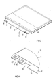
- the storage phosphor plate 10 contains a storage phosphor layer 11, which is on a carrier layer 12 is applied.
- the storage phosphor plate 10 is used to store X-ray information generated by irradiation with X-rays in the storage phosphor layer 11 can be saved.
- the storage phosphor layer 11 can in particular be a special crystallite, have needle-like structure, such as that from the patent DE 198 59 747 C1 is known.
- This special storage phosphor layer shows a variety of "needles" that are used to guide both excitation radiation, which is used to excite the storage phosphor layer, as well as from Emission radiation due to the excitation from the storage phosphor layer is emitted, can serve.
- crystalline "needles" are grown.
- Such a needle storage phosphor layer is made of alkali halides, such as. B. cesium bromide. This structured alkali halides can with suitable activators, such as. B. gallium, Thallium, Europium, etc.
- the individual needles are usually separated from each other by a small air gap. Excitation radiation, that falls into such a needle at a certain angle becomes largely forwarded without scattering until it is in the crystal lattice of the "needle" an information center where X-ray information is stored. By The emission radiation generated by the information center is stimulated in the corresponding "needle” passed on and out of this, so that it can be detected by a detection means.
- Such an acicular Storage phosphor layer is particularly from the European patent application EP 0 751 200 A1 is known. By using this special Storage phosphor layer will scatter the excitation radiation and the emission radiation within the storage phosphor layer is reduced.
- the entire carrier layer is not 12 applied the storage phosphor layer 11.
- the carrier layer 12 is not a storage phosphor layer on the carrier layer 12 applied.
- the storage phosphor plate 10 has an approximate rectangular form. It has two parallel long faces 13 and 15 and two parallel short end faces 14 and 16. The short end faces 14 and 16 run perpendicular to the long end faces 13 and 15.
- the storage phosphor plate 10 can in particular be a format with the dimensions of 14 "x17" to have.
- the area 17 in which there is no storage phosphor layer 11 on the carrier layer 12 is applied, runs approximately along the long end face 13 of the storage phosphor plate 10.
- first contour 20 within the region 17 attached to the support layer 12 for gripping the storage phosphor plate 10.
- second contour 30 within area 17. This second contour 30 serves to fix the storage phosphor plate 10 in an x-ray cassette.
- third contour 21 in the area 17 Gripping the storage phosphor plate 10 attached in the carrier layer.
- fourth contour 31 is one in the carrier layer 12 fourth contour 31. This fourth contour 31 also serves to fix the storage phosphor plate 10 in the x-ray cassette.
- the two contours 30 and 31 to fix the storage phosphor plate 10 are advantageously along here the same end face 13 attached. You are in area 17, in which there is no storage phosphor layer 11. However, it is also possible, the contours for fixing the storage phosphor plate 10 on a or to attach more of the other end faces 14, 15, 16.
- the first contour 20 and the second contour 30 are here in one piece Molded part designed. However, it is also possible to use the two contours 20 and 30 independently of one another as separate molded parts.
- the two contours 20 and 30 are made of hardened metal. This is particularly wear-resistant. But it is also possible to make the contours from plastic, in particular to manufacture a glass fiber reinforced plastic.
- the two Contours 20 and 30 are mechanically high-strength and with the carrier layer 12 precisely connected. For the sake of simplicity, this is achieved via rivets.
- exemplary are a rivet 23 in Fig. 2 on the left side of the contour 20 and a rivet 34 is shown on the right side of the contour 30.
- the two can rivet the contours 20 and 30 to the carrier layer 12 Contours 20 and 30 can be glued to the carrier layer 12. It is also possible, to weld the contours to the carrier layer, if the for the contours and the carrier layer selected materials allow this.
- the carrier layer 12 is made here from a plastic material. This plastic material is specifically for diagnostic requirements for the storage phosphor plate 10 to be asked.
- the first contour 20 is formed by means of a recess 22 which is in a Edge region of the carrier layer 12, i. H. here towards the front 13, an opening having.
- the recess 22 is L-shaped here, like a kind of hook. That is, it points here on the left side of the recess 22, towards the front side 16, a bulge 24 on.
- the gripper arm can be used for the End face 13 opening of the recess 22 into the recess 22 drive into. Then it is moved to the left into the bulge 24.
- the storage phosphor plate 10 is pulled out of the X-ray cassette he encounters resistance on the web 25, so that the pulling out of the Storage phosphor plate 10 can be effected.
- the second contour 30 is formed by means of an opening 32, which here is a circular one Has shape.
- the second contour 30 has an upper edge 33 which is frustoconical is flattened. Additionally or alternatively, the upper edge 33 be rounded.
- the second contour 30 is in an inner region of the region 17 attached to the carrier layer 12. Towards the end 13 therefore arises in the area the second contour 30 no opening. Due to the circular design the opening 32 and the frustoconical or rounded configuration of the upper edge 33, it is possible in a simple manner, the storage phosphor plate 10 to fix in the X-ray cassette.
- the opening 32 is a very precise assignment of the storage phosphor plate 10 given to the bolt.
- One in the design of the bolt and the second Contour 30 occurring game falls in all directions of the circular opening 32nd the same.
- a circular design of the second contour 30 is advantageous compared to other shapes of the contours for fixing the storage phosphor plate 10. In general, however, there are other forms of contours possible to fix.
- Fig. 3 shows an embodiment of an X-ray cassette 40, in which the Storage phosphor plate 10 is introduced. 3 protrude in the illustration the end face 13 and the area 17 behind it with the contours 20, 30, and 21, 31 out of an opening of the X-ray cassette 40.
- Fig. 4 shows a further embodiment of an embodiment of the contours for gripping the storage phosphor plate 10 and for fixing the storage phosphor plate 10 in an x-ray cassette.
- 4 shows a fifth contour 41 for gripping the storage phosphor plate 10 by a in a Direction for reading the storage phosphor plate 10 located gripper arm can serve.
- the contour 41 has a second bulge 44 on its right side on. The two bulges 43 and 44 are advantageously the same. Thereby can make the production and assembly of the storage phosphor plate 10 easier respectively.
- the contour 41 When applying the contour 41 to the carrier layer 12 must namely, no attention is paid to the alignment of the bulge of the contour 41, since the contour 41 is symmetrical.
- the second bulge 44 on the left side of the contour 41 and the first bulge 43 may be arranged on the right side of the contour 41. Both bulges 43 and 44 are the same.
- the contour 41 is so far by means of a T-shaped or anchor-shaped recess.
- FIG. 4 also shows a sixth contour 42, which is used to fix the storage phosphor plate 10 can serve in an X-ray cassette.
- the sixth Contour 42 is here through a recess made in the carrier layer 12 educated.
- the contour 42 here has a rectangular configuration and is for End face 13 open.
- As a contour for fixing the storage phosphor plate 10 is therefore not an independent one in this exemplary embodiment according to FIG. 4 Molding necessary. For example, from the inside of the X-ray cassette in the recess 42 descending, in particular rectangular bolts can the storage phosphor plate 10 fall out of an open Prevent X-ray cassette.
- the storage phosphor plate 10 in particular by a bolts engaging the contour 42 against the rear wall of the X-ray cassette be pressed.
- a gripper arm easily possible to retract into the contour 41 to the storage phosphor plate 10 to pull out of the X-ray cassette.
- 5 shows an example of a gripping arm 50 which engages in the first contour 20 Has.
- a bolt located in the gripper arm 50, in particular with a round one Cross section can easily move into the contour 20.
- 5 the upper side 53 of a bolt projecting downward into the contour 20 is shown, the retracted into the first contour 20 by means of the gripper and to Pull out and push the storage phosphor plate 10 into the X-ray cassette is used.
- 5 also shows a control flap 51, that can be attached within the x-ray cassette. On the left, directly A further bolt 52 is attached in the control flap 51 above the opening 32, which serves the storage phosphor plate 10 in the X-ray cassette to fix. The control flap 51 is folded down by a mechanism so that the bolt 52 moves into the second contour 30. This will the storage phosphor plate 10 fixed.
- Another control flap serves to fix the storage phosphor plate 10 by means of the fourth Contour 31.
- 6A shows a further exemplary embodiment for the design of the fixing contours.
- 6A shows a section of area 17 of the storage phosphor plate 10 shown.
- On the left side is a contour 62 for fixing the Storage phosphor plate 10 and on the right side another contour 63 for fixing the storage phosphor plate 10 to the storage phosphor plate 10 appropriate.
- the two contours 62 and 63 are here along the same end face 13 of the storage phosphor plate 10 arranged.
- the contour 62 is by means of formed a round opening 64 in its interior.
- the contour 63 is by means of an opening 65 is formed in its interior, which has a shape of an elongated hole.
- FIG. 6B shows a sectional illustration along the section line AA of FIG. 6A.
- a first bolt 60 and a second bolt 61 are shown serve to fix the storage phosphor plate 10 in the X-ray cassette and attached to control flaps, such as the control flap 51 of FIG. 5 are.
- the first pin 60 is above the opening 64 and the second pin 61 placed above the opening 65.
- the two bolts 60 and 61 are conical designed and movable in the vertical direction. This allows when the bolts 60 and 61 are shut down, a backlash-free positive fit with the reach both contours 62 and 63. Due to the elongated design The opening 65 avoids overdetermination of the arrangement.
- the lowered bolt 61 achieves with the contour 63 in the direction of propagation the end face 13 no form fit, but only in the vertical direction to the direction of propagation of the end face 13.
- the tolerances of the contours 62 and 63 and the bolts 60 and 61 advantageously do not have to be tight.
Landscapes
- Physics & Mathematics (AREA)
- General Physics & Mathematics (AREA)
- Conversion Of X-Rays Into Visible Images (AREA)
- Radiography Using Non-Light Waves (AREA)
- Luminescent Compositions (AREA)
Abstract
Description
- Fig. 1
- ein Ausführungsbeispiel einer erfindungsgemäßen Speicherleuchtstoffplatte mit Konturen zum Greifen und Fixieren,
- Fig. 2
- eine detailliertere Darstellung der in Fig. 1 gezeigten Konturen zum Greifen und Fixieren,
- Fig. 3
- ein Ausführungsbeispiel einer Röntgenkassette mit einer erfindungsgemäßen Speicherleuchtstoffplatte,
- Fig. 4
- ein Ausführungsbeispiel der Konturen zum Greifen und Fixieren,
- Fig. 5
- ein Beispiel eines Greifens und Fixierens der erfindungsgemäßen Speicherleuchtstoffplatte und
- Fig. 6A, B
- ein weiteres Ausführungsbeispiel von Konturen zum Fixieren und zum Fixieren verwendbaren kegelförmig ausgestalteten Fixierbolzen.
Claims (17)
- Speicherleuchtstoffplatte (10) zum Abspeichern von Bildinformationen mit einer Trägerschicht (12),
einer Speicherleuchtstoffschicht (11), die auf der Trägerschicht (12) aufgebracht ist, und
einer Kontur (20, 21), die als gegenüber der Trägerschicht (12) eigenständiges Teil ausgestaltet und mit der Trägerschicht (12) verbunden ist. - Speicherleuchtstoffplatte nach Anspruch 1, dadurch gekennzeichnet, dass die Kontur (20, 21) mittels einer Aussparung (22) gebildet ist.
- Speicherleuchtstoffplatte nach Anspruch 1 oder Anspruch 2, dadurch gekennzeichnet, dass die Kontur (20, 21) in einem Randbereich (13) der Trägerschicht (12) mit dieser verbunden ist.
- Speicherleuchtstoffplatte nach einem der vorhergehenden Ansprüche, dadurch gekennzeichnet, dass die Trägerschicht (12) aus einem ersten Material und die Kontur (20, 21) aus einem zweiten Material ist.
- Speicherleuchtstoffplatte nach einem der vorhergehenden Ansprüche, dadurch gekennzeichnet, dass die Trägerschicht (12) einen Bereich (17) aufweist, in dem keine Speicherleuchtstoffschicht (11) aufgebracht ist, und die Kontur (20, 21) in diesem Bereich (17) angeordnet ist.
- Speicherleuchtstoffplatte nach Anspruch 5, dadurch gekennzeichnet, dass sie zwei parallel zueinander angeordnete kurze Stirnseiten (14, 16) und zwei parallel zueinander angeordnete lange Stirnseiten (13, 15) hat und die Kontur (20, 21) in einer Stirnseite (13) angeordnet ist, die sich in dem Bereich (17) der Trägerschicht (12) befindet, in dem keine Speicherleuchtstoffschicht (11) aufgebracht ist.
- Speicherleuchtstoffplatte nach Anspruch 4, dadurch gekennzeichnet, dass das zweite Material der Kontur (20, 21) ein insbesondere gehärtetes Metallmaterial ist.
- Speicherleuchtstoffplatte nach einem der vorhergehenden Ansprüche, dadurch gekennzeichnet, dass die Kontur (20, 21) mit der Trägerschicht (12) vernietet ist.
- Speicherleuchtstoffplatte nach einem der vorhergehenden Ansprüche, dadurch gekennzeichnet, dass die Kontur (20, 21) mit der Trägerschicht (12) verklebt ist.
- Speicherleuchtstoffplatte nach Anspruch 2, dadurch gekennzeichnet, dass die Kontur (20, 21) mittels einer L-förmige Aussparung (22) gebildet ist.
- Speicherleuchtstoffplatte nach einem der vorhergehenden Ansprüche, dadurch gekennzeichnet, dass sie mehrere Konturen (20, 21) aufweist.
- Speicherleuchtstoffplatte nach Anspruch 11, dadurch gekennzeichnet, dass die mehreren Konturen (20, 21) in der gleichen Stirnseite (13) der Speicherleuchtstoffplatte (10) angeordnet sind.
- Speicherleuchtstoffplatte nach einem der vorhergehenden Ansprüche, dadurch gekennzeichnet, dass sie eine weitere Kontur (30, 31) zum Fixieren der Speicherleuchtstoffplatte (10) in einer Kassette (40) aufweist.
- Speicherleuchtstoffplatte nach Anspruch 13, dadurch gekennzeichnet, dass die weitere Kontur (30, 31) als gegenüber der Trägerschicht (12) eigenständiges Teil ausgestaltet und mit der Trägerschicht (12) verbunden ist.
- Speicherleuchtstoffplatte nach Anspruch 13 oder Anspruch 14, dadurch gekennzeichnet, dass die weitere Kontur (30, 31) durch eine Aussparung (42) in der Trägerschicht (12) gebildet ist.
- Speicherleuchtstoffplatte nach einem der Ansprüche 13 bis 15, dadurch gekennzeichnet, dass die weitere Kontur (30, 31) in einem Innenbereich (17) der Trägerschicht (12) angebracht ist.
- Röntgenkassette (40) mit einer Speicherleuchtstoffplatte (10) nach einem der vorhergehenden Ansprüche.
Priority Applications (4)
| Application Number | Priority Date | Filing Date | Title |
|---|---|---|---|
| EP01130409A EP1321804B1 (de) | 2001-12-20 | 2001-12-20 | Speicherleuchtstofffolie für Röntgenaufnahmen |
| DE50112570T DE50112570D1 (de) | 2001-12-20 | 2001-12-20 | Speicherleuchtstofffolie für Röntgenaufnahmen |
| AT01130409T ATE363671T1 (de) | 2001-12-20 | 2001-12-20 | Speicherleuchtstofffolie für röntgenaufnahmen |
| US10/309,719 US7005655B2 (en) | 2001-12-20 | 2002-12-04 | Storage phosphor panel for storing image information and X-ray cassette |
Applications Claiming Priority (1)
| Application Number | Priority Date | Filing Date | Title |
|---|---|---|---|
| EP01130409A EP1321804B1 (de) | 2001-12-20 | 2001-12-20 | Speicherleuchtstofffolie für Röntgenaufnahmen |
Publications (2)
| Publication Number | Publication Date |
|---|---|
| EP1321804A1 true EP1321804A1 (de) | 2003-06-25 |
| EP1321804B1 EP1321804B1 (de) | 2007-05-30 |
Family
ID=8179619
Family Applications (1)
| Application Number | Title | Priority Date | Filing Date |
|---|---|---|---|
| EP01130409A Expired - Lifetime EP1321804B1 (de) | 2001-12-20 | 2001-12-20 | Speicherleuchtstofffolie für Röntgenaufnahmen |
Country Status (4)
| Country | Link |
|---|---|
| US (1) | US7005655B2 (de) |
| EP (1) | EP1321804B1 (de) |
| AT (1) | ATE363671T1 (de) |
| DE (1) | DE50112570D1 (de) |
Cited By (3)
| Publication number | Priority date | Publication date | Assignee | Title |
|---|---|---|---|---|
| WO2007036271A1 (de) * | 2005-09-27 | 2007-04-05 | Dürr Dental GmbH & Co. KG | Positioniereinrichtung für eine speicherfolie sowie speicherfolien-auslesegerät, speicherfolienkassette und speicherfolien-handhabungseinrichtung |
| US7256413B2 (en) | 2004-09-22 | 2007-08-14 | Agfa-Gevaert Aktiengesellschaft | Device and process for reading out X-ray information stored in a phosphor plate |
| US7315040B2 (en) | 2004-09-22 | 2008-01-01 | Agfa-Gevaert Healthcare Gmbh | Device for reading out X-ray information stored in a phosphor plate |
Families Citing this family (5)
| Publication number | Priority date | Publication date | Assignee | Title |
|---|---|---|---|---|
| US7122807B2 (en) * | 2003-10-02 | 2006-10-17 | Konica Minolta Medical & Graphic Inc. | Cassette reading processing device, cassette reading processing method and cassette |
| ATE500595T1 (de) * | 2004-05-21 | 2011-03-15 | Agfa Gevaert Healthcare Gmbh | Speicherleuchtstoffplatte zur speicherung von röntgeninformation |
| ATE439005T1 (de) * | 2005-12-29 | 2009-08-15 | Agfa Gevaert Healthcare Gmbh | Antriebsvorrichtung für eine optische abtasteinrichtung |
| US7935932B2 (en) * | 2008-01-31 | 2011-05-03 | Fujifilm Corporation | Radiation detection apparatus |
| US11974869B2 (en) * | 2022-01-25 | 2024-05-07 | Kurt Hainze | Portable x-ray cassette positioning system and method |
Citations (3)
| Publication number | Priority date | Publication date | Assignee | Title |
|---|---|---|---|---|
| US5265865A (en) * | 1990-04-13 | 1993-11-30 | Fuji Photo Film Co., Ltd. | Stimulable phosphor sheet feeding and storing mechanism and stimulable phosphor sheet cassette |
| EP0851290A2 (de) * | 1996-12-25 | 1998-07-01 | Noritsu Koki Co., Ltd. | Photographischer Film |
| JP2000235239A (ja) * | 1999-02-12 | 2000-08-29 | Fuji Photo Film Co Ltd | 蓄積性蛍光体シートの搬送装置、搬送方法、および蓄積性蛍光体シート |
Family Cites Families (8)
| Publication number | Priority date | Publication date | Assignee | Title |
|---|---|---|---|---|
| US5276333A (en) * | 1991-11-27 | 1994-01-04 | Eastman Kodak Company | X-ray cassette having removable photographic element |
| EP0751200B1 (de) | 1995-06-30 | 1999-03-03 | Agfa-Gevaert N.V. | Schirm zum Speichern eines Strahlungsbildes mit Alkalihalogenidphosphor |
| US5712486A (en) * | 1996-04-15 | 1998-01-27 | Liberty Technologies, Inc. | Flexible cassette for holding storage phosphor screen |
| DE19859747C1 (de) | 1998-12-23 | 2000-02-24 | Agfa Gevaert Ag | Vorrichtung und Verfahren zum Auslesen von in einer Phosphorschicht abgespeicherten Informationen |
| US6534779B1 (en) * | 1999-02-12 | 2003-03-18 | Fuji Photo Film Co., Ltd. | Conveyance of stimulable phosphor sheet |
| US6437359B1 (en) * | 1999-11-19 | 2002-08-20 | Eastman Kodak Company | CR reader with vertical scanning |
| US6781144B2 (en) * | 2000-11-20 | 2004-08-24 | Konica Corporation | Radiation image radiographing cassette and radiation image reading apparatus |
| US6683315B2 (en) * | 2001-06-29 | 2004-01-27 | Eastman Kodak Company | Storage phosphor cassette |
-
2001
- 2001-12-20 DE DE50112570T patent/DE50112570D1/de not_active Expired - Lifetime
- 2001-12-20 EP EP01130409A patent/EP1321804B1/de not_active Expired - Lifetime
- 2001-12-20 AT AT01130409T patent/ATE363671T1/de not_active IP Right Cessation
-
2002
- 2002-12-04 US US10/309,719 patent/US7005655B2/en not_active Expired - Lifetime
Patent Citations (3)
| Publication number | Priority date | Publication date | Assignee | Title |
|---|---|---|---|---|
| US5265865A (en) * | 1990-04-13 | 1993-11-30 | Fuji Photo Film Co., Ltd. | Stimulable phosphor sheet feeding and storing mechanism and stimulable phosphor sheet cassette |
| EP0851290A2 (de) * | 1996-12-25 | 1998-07-01 | Noritsu Koki Co., Ltd. | Photographischer Film |
| JP2000235239A (ja) * | 1999-02-12 | 2000-08-29 | Fuji Photo Film Co Ltd | 蓄積性蛍光体シートの搬送装置、搬送方法、および蓄積性蛍光体シート |
Non-Patent Citations (1)
| Title |
|---|
| PATENT ABSTRACTS OF JAPAN vol. 2000, no. 11 3 January 2001 (2001-01-03) * |
Cited By (6)
| Publication number | Priority date | Publication date | Assignee | Title |
|---|---|---|---|---|
| US7256413B2 (en) | 2004-09-22 | 2007-08-14 | Agfa-Gevaert Aktiengesellschaft | Device and process for reading out X-ray information stored in a phosphor plate |
| US7315040B2 (en) | 2004-09-22 | 2008-01-01 | Agfa-Gevaert Healthcare Gmbh | Device for reading out X-ray information stored in a phosphor plate |
| WO2007036271A1 (de) * | 2005-09-27 | 2007-04-05 | Dürr Dental GmbH & Co. KG | Positioniereinrichtung für eine speicherfolie sowie speicherfolien-auslesegerät, speicherfolienkassette und speicherfolien-handhabungseinrichtung |
| JP2009510493A (ja) * | 2005-09-27 | 2009-03-12 | デュール デンタル アクチェンゲゼルシャフト | 記憶フォイル用の位置決め装置ならびに記憶フォイル読み取り機器、記憶フォイルカセット及び記憶フォイル取扱い装置 |
| JP4782839B2 (ja) * | 2005-09-27 | 2011-09-28 | デュール デンタル アクチェンゲゼルシャフト | 記憶フォイル用の位置決め装置ならびに記憶フォイル読み取り機器、記憶フォイルカセット及び記憶フォイル取扱い装置 |
| US8342749B2 (en) | 2005-09-27 | 2013-01-01 | Duerr Dental Gmbh & Co. Kg | Positioning device for a storage film and storage-film reader, storage film cassette and storage-film handling device |
Also Published As
| Publication number | Publication date |
|---|---|
| EP1321804B1 (de) | 2007-05-30 |
| ATE363671T1 (de) | 2007-06-15 |
| US20030128815A1 (en) | 2003-07-10 |
| US7005655B2 (en) | 2006-02-28 |
| DE50112570D1 (de) | 2007-07-12 |
Similar Documents
| Publication | Publication Date | Title |
|---|---|---|
| DE60133418T2 (de) | Ladeflächenverriegelung | |
| DE102017110001B4 (de) | Befestigungsvorrichtung zur Befestigung eines medizinischen Geräts | |
| DE4344739A1 (de) | Sprungwerkspannverschluß mit Verriegelungsbolzenwirkung | |
| EP1321804B1 (de) | Speicherleuchtstofffolie für Röntgenaufnahmen | |
| DE112017005891T5 (de) | Selbsttätige Verriegelung für ein Rackmontiertes Laufwerksgehäuse | |
| DE102019203873A1 (de) | Langteil-Montageaufbau für ein Klavier | |
| EP1324118B1 (de) | Speicherleuchtstofffolie für Röntgenaufnahmen | |
| DE112022002585T5 (de) | Abdeckung für eine Stossfängeröffnung | |
| DE102017121449A1 (de) | Befestigungselement zum lösbaren Verbinden von zwei Bauelementen | |
| DE102011050989A1 (de) | Befestigungselement | |
| DE102008040136A1 (de) | Transport- und Lagerbehälter aus Kunststoff mit Schiebeelement | |
| DE102019105027B4 (de) | Handgriff für Strahlungsdetektor | |
| EP1791022B1 (de) | Kassette für eine Speicherleuchtstoffplatte sowie Vorrichtung zur Entnahme der Speicherleuchtstoffplatte aus der Kassette | |
| EP0509206A2 (de) | Stossverbindung eines Kämpferprofils mit einem Rahmen- oder Sprossenprofil für Fenster, Türen od. dgl. | |
| EP1324117B1 (de) | Röntgenkassette für eine Speicherleuchtstofffolie | |
| EP2180372B1 (de) | Aufnahmevorrichtung zum Aufnehmen einer Speicherleuchtstoffplatte und Röntgenkassette | |
| DE3002504C2 (de) | Kassette für Röntgenaufnahmen | |
| DE60201153T2 (de) | Speicherphosphorkassette | |
| EP0446317A1 (de) | Leuchtenraster. | |
| EP0401404B1 (de) | Höhenverstellbare Anhängerkupplung | |
| DE102021124887A1 (de) | Magazin für die lagerung und den transport von plattenförmigen teilen | |
| DE102020104946A1 (de) | Schienenanordnung für einen Fahrzeugsitz und Fahrzeugsitz | |
| EP0321874B1 (de) | Vorrichtung zur Befestigung von Gehäusen in Öffnungen einer Schalttafel oder einer Rastersystemwand | |
| DE60308621T2 (de) | Zusammenbau eines Druckwiderlagers in dem Gestell eines Druckers | |
| DE202014004705U1 (de) | Rahmen zur Verbindung eines Streustrahlenrasters mit einem Detektor |
Legal Events
| Date | Code | Title | Description |
|---|---|---|---|
| PUAI | Public reference made under article 153(3) epc to a published international application that has entered the european phase |
Free format text: ORIGINAL CODE: 0009012 |
|
| AK | Designated contracting states |
Designated state(s): AT BE CH CY DE DK ES FI FR GB GR IE IT LI LU MC NL PT SE TR |
|
| AX | Request for extension of the european patent |
Extension state: AL LT LV MK RO SI |
|
| 17P | Request for examination filed |
Effective date: 20031229 |
|
| AKX | Designation fees paid |
Designated state(s): AT BE CH CY DE DK ES FI FR GB GR IE IT LI LU MC NL PT SE TR |
|
| RAP1 | Party data changed (applicant data changed or rights of an application transferred) |
Owner name: AGFA-GEVAERT HEALTHCARE GMBH |
|
| GRAP | Despatch of communication of intention to grant a patent |
Free format text: ORIGINAL CODE: EPIDOSNIGR1 |
|
| GRAS | Grant fee paid |
Free format text: ORIGINAL CODE: EPIDOSNIGR3 |
|
| GRAA | (expected) grant |
Free format text: ORIGINAL CODE: 0009210 |
|
| AK | Designated contracting states |
Kind code of ref document: B1 Designated state(s): AT BE CH CY DE DK ES FI FR GB GR IE IT LI LU MC NL PT SE TR |
|
| PG25 | Lapsed in a contracting state [announced via postgrant information from national office to epo] |
Ref country code: FI Free format text: LAPSE BECAUSE OF FAILURE TO SUBMIT A TRANSLATION OF THE DESCRIPTION OR TO PAY THE FEE WITHIN THE PRESCRIBED TIME-LIMIT Effective date: 20070530 |
|
| REG | Reference to a national code |
Ref country code: GB Ref legal event code: FG4D Free format text: NOT ENGLISH |
|
| GBT | Gb: translation of ep patent filed (gb section 77(6)(a)/1977) |
Effective date: 20070530 |
|
| REG | Reference to a national code |
Ref country code: CH Ref legal event code: EP |
|
| REG | Reference to a national code |
Ref country code: IE Ref legal event code: FG4D Free format text: LANGUAGE OF EP DOCUMENT: GERMAN |
|
| REF | Corresponds to: |
Ref document number: 50112570 Country of ref document: DE Date of ref document: 20070712 Kind code of ref document: P |
|
| PG25 | Lapsed in a contracting state [announced via postgrant information from national office to epo] |
Ref country code: SE Free format text: LAPSE BECAUSE OF FAILURE TO SUBMIT A TRANSLATION OF THE DESCRIPTION OR TO PAY THE FEE WITHIN THE PRESCRIBED TIME-LIMIT Effective date: 20070830 |
|
| PG25 | Lapsed in a contracting state [announced via postgrant information from national office to epo] |
Ref country code: ES Free format text: LAPSE BECAUSE OF FAILURE TO SUBMIT A TRANSLATION OF THE DESCRIPTION OR TO PAY THE FEE WITHIN THE PRESCRIBED TIME-LIMIT Effective date: 20070910 |
|
| ET | Fr: translation filed | ||
| NLV1 | Nl: lapsed or annulled due to failure to fulfill the requirements of art. 29p and 29m of the patents act | ||
| REG | Reference to a national code |
Ref country code: IE Ref legal event code: FD4D |
|
| PG25 | Lapsed in a contracting state [announced via postgrant information from national office to epo] |
Ref country code: IE Free format text: LAPSE BECAUSE OF FAILURE TO SUBMIT A TRANSLATION OF THE DESCRIPTION OR TO PAY THE FEE WITHIN THE PRESCRIBED TIME-LIMIT Effective date: 20070530 Ref country code: DK Free format text: LAPSE BECAUSE OF FAILURE TO SUBMIT A TRANSLATION OF THE DESCRIPTION OR TO PAY THE FEE WITHIN THE PRESCRIBED TIME-LIMIT Effective date: 20070530 Ref country code: NL Free format text: LAPSE BECAUSE OF FAILURE TO SUBMIT A TRANSLATION OF THE DESCRIPTION OR TO PAY THE FEE WITHIN THE PRESCRIBED TIME-LIMIT Effective date: 20070530 Ref country code: PT Free format text: LAPSE BECAUSE OF FAILURE TO SUBMIT A TRANSLATION OF THE DESCRIPTION OR TO PAY THE FEE WITHIN THE PRESCRIBED TIME-LIMIT Effective date: 20071030 |
|
| PLBE | No opposition filed within time limit |
Free format text: ORIGINAL CODE: 0009261 |
|
| STAA | Information on the status of an ep patent application or granted ep patent |
Free format text: STATUS: NO OPPOSITION FILED WITHIN TIME LIMIT |
|
| PG25 | Lapsed in a contracting state [announced via postgrant information from national office to epo] |
Ref country code: GR Free format text: LAPSE BECAUSE OF FAILURE TO SUBMIT A TRANSLATION OF THE DESCRIPTION OR TO PAY THE FEE WITHIN THE PRESCRIBED TIME-LIMIT Effective date: 20070831 Ref country code: IT Free format text: LAPSE BECAUSE OF FAILURE TO SUBMIT A TRANSLATION OF THE DESCRIPTION OR TO PAY THE FEE WITHIN THE PRESCRIBED TIME-LIMIT Effective date: 20070530 |
|
| 26N | No opposition filed |
Effective date: 20080303 |
|
| BERE | Be: lapsed |
Owner name: AGFA-GEVAERT HEALTHCARE G.M.B.H. Effective date: 20071231 |
|
| PG25 | Lapsed in a contracting state [announced via postgrant information from national office to epo] |
Ref country code: MC Free format text: LAPSE BECAUSE OF NON-PAYMENT OF DUE FEES Effective date: 20071231 |
|
| REG | Reference to a national code |
Ref country code: CH Ref legal event code: PL |
|
| PG25 | Lapsed in a contracting state [announced via postgrant information from national office to epo] |
Ref country code: BE Free format text: LAPSE BECAUSE OF NON-PAYMENT OF DUE FEES Effective date: 20071231 |
|
| PG25 | Lapsed in a contracting state [announced via postgrant information from national office to epo] |
Ref country code: CH Free format text: LAPSE BECAUSE OF NON-PAYMENT OF DUE FEES Effective date: 20071231 Ref country code: LI Free format text: LAPSE BECAUSE OF NON-PAYMENT OF DUE FEES Effective date: 20071231 |
|
| PG25 | Lapsed in a contracting state [announced via postgrant information from national office to epo] |
Ref country code: AT Free format text: LAPSE BECAUSE OF NON-PAYMENT OF DUE FEES Effective date: 20071220 |
|
| PG25 | Lapsed in a contracting state [announced via postgrant information from national office to epo] |
Ref country code: CY Free format text: LAPSE BECAUSE OF FAILURE TO SUBMIT A TRANSLATION OF THE DESCRIPTION OR TO PAY THE FEE WITHIN THE PRESCRIBED TIME-LIMIT Effective date: 20070530 |
|
| PG25 | Lapsed in a contracting state [announced via postgrant information from national office to epo] |
Ref country code: LU Free format text: LAPSE BECAUSE OF NON-PAYMENT OF DUE FEES Effective date: 20071220 |
|
| PG25 | Lapsed in a contracting state [announced via postgrant information from national office to epo] |
Ref country code: TR Free format text: LAPSE BECAUSE OF FAILURE TO SUBMIT A TRANSLATION OF THE DESCRIPTION OR TO PAY THE FEE WITHIN THE PRESCRIBED TIME-LIMIT Effective date: 20070530 |
|
| REG | Reference to a national code |
Ref country code: FR Ref legal event code: CA |
|
| REG | Reference to a national code |
Ref country code: FR Ref legal event code: PLFP Year of fee payment: 15 |
|
| REG | Reference to a national code |
Ref country code: FR Ref legal event code: PLFP Year of fee payment: 16 |
|
| REG | Reference to a national code |
Ref country code: GB Ref legal event code: 732E Free format text: REGISTERED BETWEEN 20170824 AND 20170830 |
|
| REG | Reference to a national code |
Ref country code: FR Ref legal event code: PLFP Year of fee payment: 17 |
|
| REG | Reference to a national code |
Ref country code: FR Ref legal event code: TP Owner name: AGFA HEALTHCARE NV, BE Effective date: 20171114 |
|
| REG | Reference to a national code |
Ref country code: GB Ref legal event code: 732E Free format text: REGISTERED BETWEEN 20180816 AND 20180822 |
|
| REG | Reference to a national code |
Ref country code: DE Ref legal event code: R081 Ref document number: 50112570 Country of ref document: DE Owner name: AGFA NV, BE Free format text: FORMER OWNER: AGFA-GEVAERT HEALTHCARE GMBH, 50829 KOELN, DE |
|
| PGFP | Annual fee paid to national office [announced via postgrant information from national office to epo] |
Ref country code: DE Payment date: 20191030 Year of fee payment: 19 |
|
| PGFP | Annual fee paid to national office [announced via postgrant information from national office to epo] |
Ref country code: FR Payment date: 20191030 Year of fee payment: 19 |
|
| PGFP | Annual fee paid to national office [announced via postgrant information from national office to epo] |
Ref country code: GB Payment date: 20191030 Year of fee payment: 19 |
|
| REG | Reference to a national code |
Ref country code: DE Ref legal event code: R119 Ref document number: 50112570 Country of ref document: DE |
|
| GBPC | Gb: european patent ceased through non-payment of renewal fee |
Effective date: 20201220 |
|
| PG25 | Lapsed in a contracting state [announced via postgrant information from national office to epo] |
Ref country code: FR Free format text: LAPSE BECAUSE OF NON-PAYMENT OF DUE FEES Effective date: 20201231 |
|
| PG25 | Lapsed in a contracting state [announced via postgrant information from national office to epo] |
Ref country code: GB Free format text: LAPSE BECAUSE OF NON-PAYMENT OF DUE FEES Effective date: 20201220 Ref country code: DE Free format text: LAPSE BECAUSE OF NON-PAYMENT OF DUE FEES Effective date: 20210701 |