EP1321611A1 - Verriegelungseinrichtung für eine Tür - Google Patents
Verriegelungseinrichtung für eine Tür Download PDFInfo
- Publication number
- EP1321611A1 EP1321611A1 EP02450245A EP02450245A EP1321611A1 EP 1321611 A1 EP1321611 A1 EP 1321611A1 EP 02450245 A EP02450245 A EP 02450245A EP 02450245 A EP02450245 A EP 02450245A EP 1321611 A1 EP1321611 A1 EP 1321611A1
- Authority
- EP
- European Patent Office
- Prior art keywords
- support plate
- plate
- leaf
- locking device
- spring
- Prior art date
- Legal status (The legal status is an assumption and is not a legal conclusion. Google has not performed a legal analysis and makes no representation as to the accuracy of the status listed.)
- Granted
Links
- 230000000903 blocking effect Effects 0.000 claims abstract description 9
- 230000007935 neutral effect Effects 0.000 claims 1
- 238000010586 diagram Methods 0.000 description 2
Images



Classifications
-
- E—FIXED CONSTRUCTIONS
- E05—LOCKS; KEYS; WINDOW OR DOOR FITTINGS; SAFES
- E05B—LOCKS; ACCESSORIES THEREFOR; HANDCUFFS
- E05B65/00—Locks or fastenings for special use
- E05B65/10—Locks or fastenings for special use for panic or emergency doors
- E05B65/102—Locks or fastenings for special use for panic or emergency doors opening under pressure on the surface of the door itself
-
- E—FIXED CONSTRUCTIONS
- E05—LOCKS; KEYS; WINDOW OR DOOR FITTINGS; SAFES
- E05C—BOLTS OR FASTENING DEVICES FOR WINGS, SPECIALLY FOR DOORS OR WINDOWS
- E05C7/00—Fastening devices specially adapted for two wings
- E05C7/04—Fastening devices specially adapted for two wings for wings which abut when closed
- E05C7/06—Fastening devices specially adapted for two wings for wings which abut when closed a fastening device for one wing being actuated or controlled by closing another wing
-
- E—FIXED CONSTRUCTIONS
- E05—LOCKS; KEYS; WINDOW OR DOOR FITTINGS; SAFES
- E05B—LOCKS; ACCESSORIES THEREFOR; HANDCUFFS
- E05B63/00—Locks or fastenings with special structural characteristics
- E05B63/04—Locks or fastenings with special structural characteristics for alternative use on the right-hand or left-hand side of wings
Definitions
- the invention relates to a locking system for a door with a active and a standing wing according to the preamble of the claim 1, and has the goal, in the event of fire or in a panic situation the two wings open by pressing the doors to enable.
- a locking device of the type mentioned is made known by DE 86 26 191 U1.
- This locking device is provided with a rocker-like bar that with a beam arm facing the passive leaf with a locking bolt is equipped, which is vertically through the Frame can be inserted into the passive leaf. With a vertical lock frictional forces occur, causing an automatic Unlocking is blocked. As a result, this locking mechanism no panic lock with which the passive leaf can arise from external pressure.
- the measures according to claim 2 ensure that the Standing wing can always be opened when the active wing is open is.
- the measure according to claim 3 has the advantage that the spring holds the passive leaf in the closed state without the Active leaf must be closed. With conventional locks the standing wing is only leaned against the frame, but is not locked if the active leaf is not yet closed.
- the measure according to claim 4 has the advantage that the door with the active leaf closed by folding the U-shaped blocking plate is locked in both directions.
- the measure also has a similar advantage according to claim 5.
- the door on which the invention is based has an active leaf 2 and a standing leaf 2 ', which on the upper edge of the door leaf has a spring-loaded latch 3, which with a chamfer 4 is provided and in a cylindrical guide of the passive leaf 2 is guided perpendicularly.
- a spring-loaded latch 3 which with a chamfer 4 is provided and in a cylindrical guide of the passive leaf 2 is guided perpendicularly.
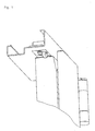
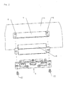
- the locking device 5 like FIGS. 3 and 4 show a base plate 12 on which by means of screws 10 a U-shaped bridge 11 is attached, in the legs 13, 13 'a support plate 14 is pivotable by means of a bearing pin 15 is mounted, which passes through the legs 13 of the bridge 11.
- the carrier part 14 has a comb-like shape, as in FIG. 4 can be seen, the webs 16 one leg 13, and the Ridges 16 'encompass the other leg 13' of bridge 11.
- the Bearing pin 15 passes through all webs 16, 16 'and has between the two inner webs 16 "of the carrier part 14 enclosing it Leg spring 17, which is biased, and with one end 17 'between the webs 16 "on the crossbar 14' of Carrier part 14 and with the other end 17 “on the base plate 12 or supported on the bridge bridge 11 '.
- a striking plate 18 On the support plate 14 is a striking plate 18 by a Screw 19 attached.
- the striking plate 18 is provided with a bevel 20 which an opening 21 passes through the base plate 12 and is used for Supporting the latch 3.
- a lifting rod for the active leaf 1 29 fastened by means of a screw 30.
- the lifting rod 29 protrudes through an opening 31 of the base plate 12.
- a U-shaped locking plate 32 is pivotable stored, which hangs down when the active leaf 1 is opened is.
- the carrier part 14 has one second opening 31 for a second lifting rod 29. However, it will only one lifting rod 29 with a locking plate 32 used because the system would otherwise lock itself.
- the blocking plate 32 must always be on active leaf 2 and never open the standing wing 2 '.
- the second opening 31 is intended for the case if the active wing 2 is not on the left but on the right, so you don't have two different types of Must build locks, but just the lifting rod 29th and subsequently also the blocking plate 32 from the first Opening 31 moved into the second opening 31. So the locking is usable left and right.
- an intermediate plate 12 ′ can be added to the base plate 12 (Fig. 4) are added. It has the advantage that the blocking plate 32 no longer supported on the base plate 12, but on the added intermediate plate 12 '. So sunk the blocking plate 32 in the base plate 12 to 2 mm. The door air between frame 6 and door leaf 2, 2 'may therefore be in the the smallest case is 2 mm. Compared to the previous version The door clearance was only allowed to be a minimum of 4 mm.
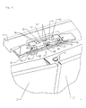
- the leg spring 17 can be on the one hand on the intermediate plate 12 'and on the other support on the carrier part 14, such as 5 can be seen.
- the shape of the leg spring 17 is out Fig. 4 recognizable.
Landscapes
- Engineering & Computer Science (AREA)
- Mechanical Engineering (AREA)
- Business, Economics & Management (AREA)
- Emergency Management (AREA)
- Specific Sealing Or Ventilating Devices For Doors And Windows (AREA)
- Lock And Its Accessories (AREA)
- Closing And Opening Devices For Wings, And Checks For Wings (AREA)
Abstract
Description
Claims (5)
- Verriegelungseinrichtung für eine Tür mit einem Geh- und einem Stehflügel mit einem lotrecht geführten, in die Verriegelungslage federbelasteten, endseitig abgeschrägten, in eine Verriegelungseinrichtung einrastbaren Riegel, sowie einer um eine horizontale Achse schwenkbaren Tragplatte, dadurch gekennzeichnet, dass auf der Tragplatte (14) eine nach unten hängende Blockierplatte (32) um eine horizontale Achse schwenkbar angelenkt ist, die in den Weg des oberen Randes des Gehflügels (2) ragt und durch diesen aus einer Blockierstellung in eine die Bewegung des Gehflügels (2) freigebende Stellung bringbar ist.
- Verriegelungseinrichtung für eine Tür nach Anspruch 1, dadurch gekennzeichnet, dass die Tragplatte (14) um einen Lagerbolzen (15) schwenkbar ist, welcher die Schenkel (13, 13') einer auf einer Grundplatte (12) befestigten U-förmigen Brücke (11) durchsetzt und von einer vorgespannten Feder (17) umschlossen ist, von welcher das eine Ende an der Brücke und das andere Ende an der Tragplatte abgestützt ist.
- Verriegelungseinrichtung nach Anspruch 2, dadurch gekennzeichnet, dass die schwenkbare Tragplatte (14) kammartig ausgebildet ist und mit jeweils zwei Schenkeln (16, 16') die Schenkeln (13, 13') umgreifen, wobei die Feder (17) zwischen den benachbarten inneren Stegen (16') am Lagerbolzen (15) angeordnet ist, welcher alle Stege (16, 16', 16") der schwenkbaren Tragplatte (14) und die Schenkel (13, 13') der Brücke (11) durchsetzt, wobei die Feder (17) mit ihrem einen Ende (17') an der Tragplatte (14) zwischen den inneren Stegen (16") und mit dem anderen Ende (17") auf der rundplatte, auf der die Brücke (11) oder auf einem anderen stationären Teil abgestützt ist.
- Verriegelungseinrichtung nach mindestens einem der vorangehenden Ansprüche, dadurch gekennzeichnet, dass auf der Tragplatte (14) sowohl für den Gehflügel (2) als auch für den Stehflügel (2) je eine Hubstange (29) befestigt ist, welche durch Öffnungen (31) der Grundplatte (12) nach unten ragt und an ihrem herausragenden Ende eine vorzugsweise U-förmige Blockierplatte (32) schwenkbar lagert und in den Weg des oberen Randes des Gehflügels (1) bzw. des Stehflügels (2) ragt und durch Bewegung des Geh- bzw. Stehflügels in eine neutrale horizontale Lage bringbar ist.
- Verriegelungseinrichtung nach mindestens einem der vorangehenden Ansprüche, dadurch gekennzeichnet, dass die Tragplatte (14) mit einem Schließblech (18) versehen ist, das eine Öffnung (21) der Grundplatte (12) durchsetzt und den Schnappriegel (3) abstützt.
Applications Claiming Priority (2)
| Application Number | Priority Date | Filing Date | Title |
|---|---|---|---|
| AT0200601A ATA20062001A (de) | 2001-12-20 | 2001-12-20 | Verriegelungseinrichtung für eine tür |
| AT20062001 | 2001-12-20 |
Publications (2)
| Publication Number | Publication Date |
|---|---|
| EP1321611A1 true EP1321611A1 (de) | 2003-06-25 |
| EP1321611B1 EP1321611B1 (de) | 2004-12-29 |
Family
ID=3689601
Family Applications (1)
| Application Number | Title | Priority Date | Filing Date |
|---|---|---|---|
| EP02450245A Expired - Lifetime EP1321611B1 (de) | 2001-12-20 | 2002-10-28 | Verriegelungseinrichtung für eine Tür |
Country Status (3)
| Country | Link |
|---|---|
| EP (1) | EP1321611B1 (de) |
| AT (2) | ATA20062001A (de) |
| DE (1) | DE50201884D1 (de) |
Cited By (1)
| Publication number | Priority date | Publication date | Assignee | Title |
|---|---|---|---|---|
| AT394768B (de) * | 1990-11-02 | 1992-06-25 | Chamottewaren U Thonoefenfabri | Brennerflammenfuehrungsteil |
Citations (4)
| Publication number | Priority date | Publication date | Assignee | Title |
|---|---|---|---|---|
| DE3436749A1 (de) * | 1984-07-04 | 1986-01-23 | Franz Dipl.-Ing. 5760 Arnsberg Kraft | Panikentriegelung einer zweifluegeligen tuer |
| DE8626191U1 (de) * | 1986-10-01 | 1986-11-13 | Echt & Co Nachf. Schulte Gmbh & Co Kg, 5750 Menden | Vorrichtung zur Ver- und Entriegelung einer zweiflügeligen Tür |
| FR2601062A1 (fr) * | 1986-07-07 | 1988-01-08 | Lasnet Jean Pierre | Loquet de verrouillage a pene pivotant, destine notamment a une partie comportant une fermeture antipanique. |
| US5161837A (en) * | 1991-07-23 | 1992-11-10 | Thomas Industries Inc., Builders Brass Works Div. | Rod and case assembly and panic exit device |
-
2001
- 2001-12-20 AT AT0200601A patent/ATA20062001A/de not_active Application Discontinuation
-
2002
- 2002-10-28 AT AT02450245T patent/ATE286188T1/de not_active IP Right Cessation
- 2002-10-28 DE DE50201884T patent/DE50201884D1/de not_active Expired - Fee Related
- 2002-10-28 EP EP02450245A patent/EP1321611B1/de not_active Expired - Lifetime
Patent Citations (4)
| Publication number | Priority date | Publication date | Assignee | Title |
|---|---|---|---|---|
| DE3436749A1 (de) * | 1984-07-04 | 1986-01-23 | Franz Dipl.-Ing. 5760 Arnsberg Kraft | Panikentriegelung einer zweifluegeligen tuer |
| FR2601062A1 (fr) * | 1986-07-07 | 1988-01-08 | Lasnet Jean Pierre | Loquet de verrouillage a pene pivotant, destine notamment a une partie comportant une fermeture antipanique. |
| DE8626191U1 (de) * | 1986-10-01 | 1986-11-13 | Echt & Co Nachf. Schulte Gmbh & Co Kg, 5750 Menden | Vorrichtung zur Ver- und Entriegelung einer zweiflügeligen Tür |
| US5161837A (en) * | 1991-07-23 | 1992-11-10 | Thomas Industries Inc., Builders Brass Works Div. | Rod and case assembly and panic exit device |
Cited By (1)
| Publication number | Priority date | Publication date | Assignee | Title |
|---|---|---|---|---|
| AT394768B (de) * | 1990-11-02 | 1992-06-25 | Chamottewaren U Thonoefenfabri | Brennerflammenfuehrungsteil |
Also Published As
| Publication number | Publication date |
|---|---|
| DE50201884D1 (de) | 2005-02-03 |
| ATA20062001A (de) | 2005-10-15 |
| ATE286188T1 (de) | 2005-01-15 |
| EP1321611B1 (de) | 2004-12-29 |
Similar Documents
| Publication | Publication Date | Title |
|---|---|---|
| EP0103725B1 (de) | Beschlag für einen zumindest parallelabstellbaren Flügel eines Fensters, einer Tür od. dgl. | |
| DE2348998C2 (de) | Panikverschluß an Türen | |
| EP0444084B1 (de) | In türen und wände einsetzbare durchreichevorrichtung | |
| EP2133494B1 (de) | Sicherheitsverriegelungsvorrichtung mit Fluchtentriegelungseinrichtung | |
| DE2705188A1 (de) | Sicherungssystem fuer schwenkfluegelfenster | |
| DE3935803C2 (de) | ||
| EP2673446A1 (de) | Schutzgitter | |
| DE2422570A1 (de) | Schraegdachfenster | |
| EP1321611B1 (de) | Verriegelungseinrichtung für eine Tür | |
| AT9770U1 (de) | Personenschleuse | |
| EP0637668B1 (de) | Verschluss- und Spaltlüftvorrichtung für ein-, zwei- oder mehrflügelige Läden von Fenstern, Türen und dergleichen | |
| EP0262347B1 (de) | Ausstellvorrichtung für den wenigstens drehbaren Flügel eines Fensters, einer Tür od. dgl. | |
| DE19906232B4 (de) | Vorrichtung zum Ver- und Entriegeln eines Standflügels | |
| DE19638551C1 (de) | Scharnierbeschlag für Türen | |
| DE60201616T2 (de) | Feststeller für Tür, Fenster dgl. mit treibstangenverschlussartigen Beschlag | |
| EP1405973B1 (de) | Beschlagmechanik für ein Drehkippfenster oder eine Drehkipptüre | |
| EP1018592A1 (de) | Verriegelungsvorrichtung für ein Verschlussorgan einer Gebäudeöffnung, insbesondere einen Rolladen | |
| DE2526324C3 (de) | Rolladen-Verriegelung | |
| DE602004005309T2 (de) | Tür und mit einer tür versehene anordnung | |
| DE2232662A1 (de) | Einrichtung zur sicherung eines rolladens | |
| DE9403993U1 (de) | Dachfenster | |
| DE202025102288U1 (de) | Absperrvorrichtung | |
| AT398457B (de) | Personenschleuse | |
| DE1559937C (de) | Vorrichtung zum Abschwenken von Har monikaturen od dgl | |
| DE202017102806U1 (de) | Kinderschutzgitter |
Legal Events
| Date | Code | Title | Description |
|---|---|---|---|
| PUAI | Public reference made under article 153(3) epc to a published international application that has entered the european phase |
Free format text: ORIGINAL CODE: 0009012 |
|
| AK | Designated contracting states |
Designated state(s): AT BE BG CH CY CZ DE DK EE ES FI FR GB GR IE IT LI LU MC NL PT SE SK TR |
|
| AX | Request for extension of the european patent |
Extension state: AL LT LV MK RO SI |
|
| 17P | Request for examination filed |
Effective date: 20031217 |
|
| AKX | Designation fees paid |
Designated state(s): AT BE BG CH CY CZ DE DK EE ES FI FR GB GR IE IT LI LU MC NL PT SE SK TR |
|
| GRAP | Despatch of communication of intention to grant a patent |
Free format text: ORIGINAL CODE: EPIDOSNIGR1 |
|
| GRAS | Grant fee paid |
Free format text: ORIGINAL CODE: EPIDOSNIGR3 |
|
| GRAA | (expected) grant |
Free format text: ORIGINAL CODE: 0009210 |
|
| AK | Designated contracting states |
Kind code of ref document: B1 Designated state(s): AT BE BG CH CY CZ DE DK EE ES FI FR GB GR IE IT LI LU MC NL PT SE SK TR |
|
| PG25 | Lapsed in a contracting state [announced via postgrant information from national office to epo] |
Ref country code: IT Free format text: LAPSE BECAUSE OF FAILURE TO SUBMIT A TRANSLATION OF THE DESCRIPTION OR TO PAY THE FEE WITHIN THE PRESCRIBED TIME-LIMIT;WARNING: LAPSES OF ITALIAN PATENTS WITH EFFECTIVE DATE BEFORE 2007 MAY HAVE OCCURRED AT ANY TIME BEFORE 2007. THE CORRECT EFFECTIVE DATE MAY BE DIFFERENT FROM THE ONE RECORDED. Effective date: 20041229 Ref country code: EE Free format text: LAPSE BECAUSE OF FAILURE TO SUBMIT A TRANSLATION OF THE DESCRIPTION OR TO PAY THE FEE WITHIN THE PRESCRIBED TIME-LIMIT Effective date: 20041229 Ref country code: FR Free format text: LAPSE BECAUSE OF FAILURE TO SUBMIT A TRANSLATION OF THE DESCRIPTION OR TO PAY THE FEE WITHIN THE PRESCRIBED TIME-LIMIT Effective date: 20041229 Ref country code: TR Free format text: LAPSE BECAUSE OF FAILURE TO SUBMIT A TRANSLATION OF THE DESCRIPTION OR TO PAY THE FEE WITHIN THE PRESCRIBED TIME-LIMIT Effective date: 20041229 Ref country code: GB Free format text: LAPSE BECAUSE OF FAILURE TO SUBMIT A TRANSLATION OF THE DESCRIPTION OR TO PAY THE FEE WITHIN THE PRESCRIBED TIME-LIMIT Effective date: 20041229 Ref country code: NL Free format text: LAPSE BECAUSE OF FAILURE TO SUBMIT A TRANSLATION OF THE DESCRIPTION OR TO PAY THE FEE WITHIN THE PRESCRIBED TIME-LIMIT Effective date: 20041229 Ref country code: IE Free format text: LAPSE BECAUSE OF FAILURE TO SUBMIT A TRANSLATION OF THE DESCRIPTION OR TO PAY THE FEE WITHIN THE PRESCRIBED TIME-LIMIT Effective date: 20041229 Ref country code: SK Free format text: LAPSE BECAUSE OF FAILURE TO SUBMIT A TRANSLATION OF THE DESCRIPTION OR TO PAY THE FEE WITHIN THE PRESCRIBED TIME-LIMIT Effective date: 20041229 Ref country code: BG Free format text: LAPSE BECAUSE OF FAILURE TO SUBMIT A TRANSLATION OF THE DESCRIPTION OR TO PAY THE FEE WITHIN THE PRESCRIBED TIME-LIMIT Effective date: 20041229 Ref country code: CZ Free format text: LAPSE BECAUSE OF FAILURE TO SUBMIT A TRANSLATION OF THE DESCRIPTION OR TO PAY THE FEE WITHIN THE PRESCRIBED TIME-LIMIT Effective date: 20041229 Ref country code: FI Free format text: LAPSE BECAUSE OF FAILURE TO SUBMIT A TRANSLATION OF THE DESCRIPTION OR TO PAY THE FEE WITHIN THE PRESCRIBED TIME-LIMIT Effective date: 20041229 |
|
| REG | Reference to a national code |
Ref country code: GB Ref legal event code: FG4D Free format text: NOT ENGLISH |
|
| REG | Reference to a national code |
Ref country code: CH Ref legal event code: NV Representative=s name: KELLER & PARTNER PATENTANWAELTE AG Ref country code: CH Ref legal event code: EP |
|
| REG | Reference to a national code |
Ref country code: IE Ref legal event code: FG4D Free format text: GERMAN |
|
| REF | Corresponds to: |
Ref document number: 50201884 Country of ref document: DE Date of ref document: 20050203 Kind code of ref document: P |
|
| PG25 | Lapsed in a contracting state [announced via postgrant information from national office to epo] |
Ref country code: SE Free format text: LAPSE BECAUSE OF FAILURE TO SUBMIT A TRANSLATION OF THE DESCRIPTION OR TO PAY THE FEE WITHIN THE PRESCRIBED TIME-LIMIT Effective date: 20050329 Ref country code: GR Free format text: LAPSE BECAUSE OF FAILURE TO SUBMIT A TRANSLATION OF THE DESCRIPTION OR TO PAY THE FEE WITHIN THE PRESCRIBED TIME-LIMIT Effective date: 20050329 Ref country code: DK Free format text: LAPSE BECAUSE OF FAILURE TO SUBMIT A TRANSLATION OF THE DESCRIPTION OR TO PAY THE FEE WITHIN THE PRESCRIBED TIME-LIMIT Effective date: 20050329 |
|
| PG25 | Lapsed in a contracting state [announced via postgrant information from national office to epo] |
Ref country code: ES Free format text: LAPSE BECAUSE OF FAILURE TO SUBMIT A TRANSLATION OF THE DESCRIPTION OR TO PAY THE FEE WITHIN THE PRESCRIBED TIME-LIMIT Effective date: 20050409 |
|
| NLV1 | Nl: lapsed or annulled due to failure to fulfill the requirements of art. 29p and 29m of the patents act | ||
| GBV | Gb: ep patent (uk) treated as always having been void in accordance with gb section 77(7)/1977 [no translation filed] |
Effective date: 20041229 |
|
| REG | Reference to a national code |
Ref country code: IE Ref legal event code: FD4D |
|
| PG25 | Lapsed in a contracting state [announced via postgrant information from national office to epo] |
Ref country code: CY Free format text: LAPSE BECAUSE OF FAILURE TO SUBMIT A TRANSLATION OF THE DESCRIPTION OR TO PAY THE FEE WITHIN THE PRESCRIBED TIME-LIMIT Effective date: 20051028 |
|
| PG25 | Lapsed in a contracting state [announced via postgrant information from national office to epo] |
Ref country code: BE Free format text: LAPSE BECAUSE OF NON-PAYMENT OF DUE FEES Effective date: 20051031 Ref country code: MC Free format text: LAPSE BECAUSE OF NON-PAYMENT OF DUE FEES Effective date: 20051031 Ref country code: LU Free format text: LAPSE BECAUSE OF NON-PAYMENT OF DUE FEES Effective date: 20051031 |
|
| PLBE | No opposition filed within time limit |
Free format text: ORIGINAL CODE: 0009261 |
|
| STAA | Information on the status of an ep patent application or granted ep patent |
Free format text: STATUS: NO OPPOSITION FILED WITHIN TIME LIMIT |
|
| 26N | No opposition filed |
Effective date: 20050930 |
|
| EN | Fr: translation not filed | ||
| BERE | Be: lapsed |
Owner name: *STEBA BRANDSCHUTZTORE G.M.B.H. Effective date: 20051031 |
|
| PG25 | Lapsed in a contracting state [announced via postgrant information from national office to epo] |
Ref country code: PT Free format text: LAPSE BECAUSE OF NON-PAYMENT OF DUE FEES Effective date: 20050529 |
|
| PGFP | Annual fee paid to national office [announced via postgrant information from national office to epo] |
Ref country code: CH Payment date: 20080919 Year of fee payment: 7 |
|
| PGFP | Annual fee paid to national office [announced via postgrant information from national office to epo] |
Ref country code: DE Payment date: 20080812 Year of fee payment: 7 |
|
| PGFP | Annual fee paid to national office [announced via postgrant information from national office to epo] |
Ref country code: AT Payment date: 20081024 Year of fee payment: 7 |
|
| REG | Reference to a national code |
Ref country code: CH Ref legal event code: PL |
|
| PG25 | Lapsed in a contracting state [announced via postgrant information from national office to epo] |
Ref country code: DE Free format text: LAPSE BECAUSE OF NON-PAYMENT OF DUE FEES Effective date: 20100501 |
|
| PG25 | Lapsed in a contracting state [announced via postgrant information from national office to epo] |
Ref country code: AT Free format text: LAPSE BECAUSE OF NON-PAYMENT OF DUE FEES Effective date: 20091028 |
|
| PG25 | Lapsed in a contracting state [announced via postgrant information from national office to epo] |
Ref country code: LI Free format text: LAPSE BECAUSE OF NON-PAYMENT OF DUE FEES Effective date: 20091031 Ref country code: CH Free format text: LAPSE BECAUSE OF NON-PAYMENT OF DUE FEES Effective date: 20091031 |