EP1321317A1 - Anhängervorrichtung für Kraftfahrzeuge - Google Patents
Anhängervorrichtung für Kraftfahrzeuge Download PDFInfo
- Publication number
- EP1321317A1 EP1321317A1 EP02025841A EP02025841A EP1321317A1 EP 1321317 A1 EP1321317 A1 EP 1321317A1 EP 02025841 A EP02025841 A EP 02025841A EP 02025841 A EP02025841 A EP 02025841A EP 1321317 A1 EP1321317 A1 EP 1321317A1
- Authority
- EP
- European Patent Office
- Prior art keywords
- locking
- cone
- locking pin
- upper cylinder
- ball
- Prior art date
- Legal status (The legal status is an assumption and is not a legal conclusion. Google has not performed a legal analysis and makes no representation as to the accuracy of the status listed.)
- Granted
Links
Images

Classifications
-
- B—PERFORMING OPERATIONS; TRANSPORTING
- B60—VEHICLES IN GENERAL
- B60D—VEHICLE CONNECTIONS
- B60D1/00—Traction couplings; Hitches; Draw-gear; Towing devices
- B60D1/01—Traction couplings or hitches characterised by their type
- B60D1/06—Ball-and-socket hitches, e.g. constructional details, auxiliary devices, their arrangement on the vehicle
-
- B—PERFORMING OPERATIONS; TRANSPORTING
- B60—VEHICLES IN GENERAL
- B60D—VEHICLE CONNECTIONS
- B60D1/00—Traction couplings; Hitches; Draw-gear; Towing devices
- B60D1/48—Traction couplings; Hitches; Draw-gear; Towing devices characterised by the mounting
- B60D1/52—Traction couplings; Hitches; Draw-gear; Towing devices characterised by the mounting removably mounted
Definitions
- the invention relates to a hitch for motor vehicles such as cars, trucks or small off-road vehicles, including a removable one, with a spherical head and an angled end for insertion into a guide sleeve fixed to the vehicle trained ball neck, the introducer in the direction of its longitudinal axis a central locking pin that holds a locking pin head with a upper cone, an upper cylinder adjoining it downwards, has a central cone and a lower cylinder, the central one Cone for locking to at least one locking means arranged in the ball neck acts so that this partially disengaged when the locking bolt is immersed is and enters a corresponding recess of the guide sleeve.
- hitching devices are well known in the prior art, for example from DE 29 35 474 C2. So that at times without use the ball rod (ball neck with the head and the introducer) of the towbar on the outside of the vehicle must be carried, this is designed to be removable. The one remaining on the vehicle Part of the hitch with the locking mechanism is usually arranged that it is no longer visible from the outside or from a cover plate is closed.
- the locking bolt has a specific one to apply force to the locking balls Geometry on.
- the areas important for locking are here the top cylinder and the middle cone.
- the upper cylindrical area should prevent an axial return movement of the locking pin if the self-locking effect of the middle cone is no longer sufficient and the Locking pin head by applying force to the locking balls moved down.
- the invention has for its object a generic hitch with locking device to create a return movement of the locking pin limited or largely reduced.
- a preferred embodiment of the invention provides that the upper cylinder with a constricting radius, based on the longitudinal axis of the locking bolt, is designed as an undercut. Due to the waist of this constriction in the transition between the cylindrical area and the middle The cone becomes an identical diameter for the cylindrical end and the conical Start of the locking pin reached, i.e. a parallel shift to the outside. This allows the return movement of the locking pin in the locking mechanism reduce to a minimum.
- the upper Cylinder is provided with an opposite slope towards the middle cone.
- Both geometrical variants of the locking pin allow the limitation the return movement in the locking mechanism, which due to strong load changes with large trailer loads is still favored because the Undercut brakes the locking pin so that it never suddenly can change its position.
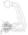
- the hitch 1 shown in Fig. 1 has a vertically extending Guide sleeve 2, which is attached to a cross member 3, the stationary on one Vehicle is arranged.
- the guide sleeve 2 serves to receive a removable ball neck 4 with a ball head 5 (in total also ball rod called), the ball neck 4 for insertion into the guide sleeve 2 an angled Introducer 6 has.
- As an end stop when inserting the ball neck 4 in the guide sleeve 2 and at the same time serve as an anti-rotation device two diametrically opposite, approximately triangular on both sides of the ball neck 4 Pin 7, which in complementary guide recesses 8 at the bottom Engage the end of the sleeve 2.
- a locking pin 10 is inserted, which is at a distance from upper, sealed by a screw cap 9 introducer is arranged and is formed at its lower end with a rack 11, which can be adjusted by means of a handwheel 12.
- the locking pin 10 is in the installed position axially acted upon by a compression spring 13 and acts on in the embodiment balls 15 inserted into radial bores 14 in the ball neck 4 - here there are three balls distributed around the circumference, which are connected with a spherical cap in corresponding cutouts 16 on the inner wall of the guide sleeve 2 arranged bearing ring 17 are pressed.
- the ball neck 4 locked in rotation with the guide sleeve 2 via its introducer 6.
- Balls could alternatively e.g. pins are also used as locking means, in the simplest case, a ball or a pin or the like is sufficient could be.
- the locking pin 10 has a secure locking a special geometry.
- the locking pin 10 consists of both Designs from an upper cone 18, an adjoining one upper cylinder 19, a middle cone 20 and a lower cylinder 21.
- Der middle cone 20 of the locking bolt 10 each has a cone angle of 3 ° on. Due to the smaller cone angle compared to conventional cone angles of 3 ° a higher self-locking is achieved in the locked state. Moreover a possible return movement of the locking pin 10 is caused of different loads on the ball head 5, reduced.
- FIG. 3 an embodiment of the locking pin 10 is shown, in which the upper Cylinder 19 with an undercut 25, here as a constriction or constriction Radius 23, based on the longitudinal axis of the locking pin 10 is formed.
- This makes the diameter in the transition region identical to the upper cylinder 19 reached to the middle cone 20.
- the upper cylindrical area in combination with the constriction 23 limits a total return movement the locking pin 10, if the self-locking effect of the middle Not cone 20 at very high loads on ball neck 4 and ball head 5 is sufficient and the locking pin 10 by the application of force to the locking balls 15 moved down.
- Such a movement limitation will also achieved when the locking pin 10 according to the alternative shown in Figure 2 on the upper cylinder 19 as an undercut 25 with an opposite slope 22 is formed towards the middle cone 20.
- a lower cone 24 is formed with a cone angle greater than 3 °.
- the increase in the lower cone angle towards the lower cylinder 21 enables an additional inhibition of the locking pin 10, causing a too wide Slipping of the locking pin 10 is prevented upwards. Still arises thus no play between the locking balls 15 and the locking pin 10th
- the length of the lower cone 24 can vary, cf. 2 and 3, so that each a sufficient adjustment travel of the Locking bolt 10 is guaranteed.
Landscapes
- Engineering & Computer Science (AREA)
- Transportation (AREA)
- Mechanical Engineering (AREA)
- Motor Or Generator Cooling System (AREA)
- Fluid-Damping Devices (AREA)
- Hooks, Suction Cups, And Attachment By Adhesive Means (AREA)
- Mutual Connection Of Rods And Tubes (AREA)
- Manufacture Of Motors, Generators (AREA)
- Motor Or Generator Frames (AREA)
- Snaps, Bayonet Connections, Set Pins, And Snap Rings (AREA)
Abstract
Description
- Fig. 1
- einen Teilschnitt durch eine Verriegelungseinrichtung einer Anhängevorrichtung;
- Fig. 2
- einen Sperrbolzen der Verriegelungseinrichtung in der Seitenansicht dargestellt; und
- Fig. 3
- eine weitere Ausführung eines Sperrbolzens in der Seitenansicht dargestellt.
Claims (3)
- Anhängevorrichtung (1) für Kraftfahrzeuge, umfassend einen abnehmbaren, mit einem Kugelkopf (5) und einem abgewinkelten Ende zum Einführen in eine fahrzeugfeste Führungshülse (2) ausgebildeten Kugelhals (4), wobei das Einführende (6) in Richtung seiner Längsachse einen zentralen Sperrbolzen (10) aufnimmt, der einen Sperrbolzenkopf mit einem oberen Konus (18), einem sich daran nach unten anschließenden oberen Zylinder (19), einem mittleren Konus (20) und einem unteren Zylinder (21) aufweist, dessen mittlerer Konus (20) zur Verriegelung auf mindestens ein im Kugelhals (4) angeordnetes Rastmittel (15) einwirkt, so daß dieses beim Eintauchen des Sperrbolzens (10) teilweise ausgerückt wird und in eine korrespondierende Ausnehmung (16) der Führungshülse (2) eintritt,
dadurch gekennzeichnet, daß der obere Zylinder (19) mit einer Hinterschneidung (25) versehen ist. - Anhängevorrichtung nach Anspruch 1,
dadurch gekennzeichnet, daß der obere Zylinder (19) mit einer Einschnürung (23) ausgebildet ist. - Anhängevorrichtung nach Anspruch 1,
dadurch gekennzeichnet, daß der obere Zylinder (19) mit einer gegenläufigen Schräge (22) hin zum mittleren Konus (20) versehen ist.
Applications Claiming Priority (2)
| Application Number | Priority Date | Filing Date | Title |
|---|---|---|---|
| DE20120531U | 2001-12-19 | ||
| DE20120531U DE20120531U1 (de) | 2001-12-19 | 2001-12-19 | Anhängervorrichtung für Kraftfahrzeuge |
Publications (2)
| Publication Number | Publication Date |
|---|---|
| EP1321317A1 true EP1321317A1 (de) | 2003-06-25 |
| EP1321317B1 EP1321317B1 (de) | 2007-04-18 |
Family
ID=7965351
Family Applications (1)
| Application Number | Title | Priority Date | Filing Date |
|---|---|---|---|
| EP02025841A Expired - Lifetime EP1321317B1 (de) | 2001-12-19 | 2002-11-19 | Anhängervorrichtung für Kraftfahrzeuge |
Country Status (3)
| Country | Link |
|---|---|
| EP (1) | EP1321317B1 (de) |
| AT (1) | ATE359925T1 (de) |
| DE (2) | DE20120531U1 (de) |
Cited By (5)
| Publication number | Priority date | Publication date | Assignee | Title |
|---|---|---|---|---|
| EP1829716A1 (de) | 2006-03-01 | 2007-09-05 | WESTFALIA - Automotive GmbH | Anhängerkupplung für Kraftfahrzeuge |
| DE102007041582A1 (de) | 2007-09-01 | 2009-03-05 | Westfalia-Automotive Gmbh | Anhängekupplung |
| EP2130696A1 (de) | 2008-06-06 | 2009-12-09 | WESTFALIA - Automotive GmbH | Anhängekupplung mit einem Sensor |
| EP2130700A1 (de) | 2008-06-06 | 2009-12-09 | WESTFALIA - Automotive GmbH | Kupplungsarm für eine Anhängekupplung |
| DE102008034846A1 (de) | 2008-06-06 | 2009-12-17 | Westfalia-Automotive Gmbh | Halter für einen Kupplungsarm einer Anhängekupplung |
Families Citing this family (3)
| Publication number | Priority date | Publication date | Assignee | Title |
|---|---|---|---|---|
| DE102009018019A1 (de) | 2009-04-18 | 2010-10-21 | Fac Frank Abels Consulting & Technology Gesellschaft Mbh | Anhängevorrichtung für Kraftfahrzeuge |
| DE102009018017A1 (de) | 2009-04-18 | 2010-10-21 | Fac Frank Abels Consulting & Technology Gesellschaft Mbh | Anhängevorrichtung für Kraftfahrzeuge |
| DE102009018018A1 (de) | 2009-04-18 | 2010-10-21 | Fac Frank Abels Consulting & Technology Gesellschaft Mbh | Anhängevorrichtung für Kraftfahrzeuge |
Citations (6)
| Publication number | Priority date | Publication date | Assignee | Title |
|---|---|---|---|---|
| DE2822662A1 (de) * | 1978-05-24 | 1979-11-29 | Eberhardt Peka Fahrzeug | Abnehmbare kupplungskugel mit halterung |
| DE2935474C2 (de) | 1979-09-01 | 1982-04-29 | Daimler-Benz Ag, 7000 Stuttgart | Anhängevorrichtung, insbesondere für Personenkraftwagen. |
| DE3541904A1 (de) * | 1985-11-27 | 1987-06-04 | Daimler Benz Ag | Anhaengerkupplung fuer fahrzeuge |
| DE3601505A1 (de) * | 1986-01-20 | 1987-07-23 | Juergens Walter | Anhaengevorrichtung |
| EP0593983A1 (de) * | 1992-10-23 | 1994-04-27 | MVG METALLVERARBEITUNGSGESELLSCHAFT mbH | Anhängekupplung |
| EP1184212A2 (de) * | 2000-09-02 | 2002-03-06 | MVG METALLVERARBEITUNGSGESELLSCHAFT mbH | Anhängekupplung |
-
2001
- 2001-12-19 DE DE20120531U patent/DE20120531U1/de not_active Expired - Lifetime
-
2002
- 2002-11-19 EP EP02025841A patent/EP1321317B1/de not_active Expired - Lifetime
- 2002-11-19 AT AT02025841T patent/ATE359925T1/de not_active IP Right Cessation
- 2002-11-19 DE DE50209965T patent/DE50209965D1/de not_active Expired - Lifetime
Patent Citations (6)
| Publication number | Priority date | Publication date | Assignee | Title |
|---|---|---|---|---|
| DE2822662A1 (de) * | 1978-05-24 | 1979-11-29 | Eberhardt Peka Fahrzeug | Abnehmbare kupplungskugel mit halterung |
| DE2935474C2 (de) | 1979-09-01 | 1982-04-29 | Daimler-Benz Ag, 7000 Stuttgart | Anhängevorrichtung, insbesondere für Personenkraftwagen. |
| DE3541904A1 (de) * | 1985-11-27 | 1987-06-04 | Daimler Benz Ag | Anhaengerkupplung fuer fahrzeuge |
| DE3601505A1 (de) * | 1986-01-20 | 1987-07-23 | Juergens Walter | Anhaengevorrichtung |
| EP0593983A1 (de) * | 1992-10-23 | 1994-04-27 | MVG METALLVERARBEITUNGSGESELLSCHAFT mbH | Anhängekupplung |
| EP1184212A2 (de) * | 2000-09-02 | 2002-03-06 | MVG METALLVERARBEITUNGSGESELLSCHAFT mbH | Anhängekupplung |
Cited By (9)
| Publication number | Priority date | Publication date | Assignee | Title |
|---|---|---|---|---|
| EP1829716A1 (de) | 2006-03-01 | 2007-09-05 | WESTFALIA - Automotive GmbH | Anhängerkupplung für Kraftfahrzeuge |
| DE102007041582A1 (de) | 2007-09-01 | 2009-03-05 | Westfalia-Automotive Gmbh | Anhängekupplung |
| EP2042353A1 (de) | 2007-09-01 | 2009-04-01 | WESTFALIA - Automotive GmbH | Anhängekupplung |
| EP2130696A1 (de) | 2008-06-06 | 2009-12-09 | WESTFALIA - Automotive GmbH | Anhängekupplung mit einem Sensor |
| EP2130700A1 (de) | 2008-06-06 | 2009-12-09 | WESTFALIA - Automotive GmbH | Kupplungsarm für eine Anhängekupplung |
| DE102008034850A1 (de) | 2008-06-06 | 2009-12-17 | Westfalia-Automotive Gmbh | Anhängekupplung mit einem Sensor |
| DE102008034846A1 (de) | 2008-06-06 | 2009-12-17 | Westfalia-Automotive Gmbh | Halter für einen Kupplungsarm einer Anhängekupplung |
| DE102008034853A1 (de) | 2008-06-06 | 2009-12-17 | Westfalia-Automotive Gmbh | Kupplungsarm für eine Anhängekupplung |
| DE102008034846B4 (de) * | 2008-06-06 | 2015-02-12 | Westfalia-Automotive Gmbh | Halter für einen Kupplungsarm einer Anhängekupplung |
Also Published As
| Publication number | Publication date |
|---|---|
| DE50209965D1 (de) | 2007-05-31 |
| EP1321317B1 (de) | 2007-04-18 |
| ATE359925T1 (de) | 2007-05-15 |
| DE20120531U1 (de) | 2002-05-23 |
Similar Documents
| Publication | Publication Date | Title |
|---|---|---|
| EP0413197B1 (de) | Lenkrolle für verfahrbare Arbeitsbühnen, Gerüste od.dgl. | |
| EP1475253A1 (de) | Anhängekupplung für Kraftfahrzeuge | |
| EP1829716B1 (de) | Anhängerkupplung für Kraftfahrzeuge | |
| EP1321317B1 (de) | Anhängervorrichtung für Kraftfahrzeuge | |
| EP0789986B1 (de) | Hubstange für die Dreipunktanbauvorrichtung eines Traktors | |
| EP1321316B1 (de) | Anhängervorrichtung für Kraftfahrzeuge | |
| WO1997037862A1 (de) | Anhängevorrichtung | |
| DE2161580B2 (de) | Vorrichtung zum Verstellen und Feststellen der Höhe von Zuggabeln an Anhängern | |
| DE4412088B4 (de) | Anhängerkupplung | |
| EP0875439B1 (de) | Spann- und Klemmvorrichtung | |
| DE19748117C2 (de) | Kugelzapfen | |
| DE69812317T2 (de) | Lenksystem, Lenkrad und Lenkradsäule für ein solches System | |
| DE19812472C2 (de) | Hebeeinrichtung zum Anheben schwerer Lasten, insbesondere entgleister Schienenfahrzeuge | |
| EP1069020B1 (de) | Zugeinrichtung für Schienenfahrzeuge. | |
| DE3419322A1 (de) | Trennbare anhaengerkupplung fuer kraftfahrzeuge | |
| DE19905299B4 (de) | Anordnung bei Lagerzapfen | |
| EP0965466A1 (de) | Kardanische Anhängekupplung | |
| DE202019104457U1 (de) | Haltergehäuse für einen Türfeststeller sowie Türfeststeller | |
| DE4238590C2 (de) | Abstützvorrichtung für eine Ladepritsche eines Fahrzeuges | |
| DE3625676A1 (de) | Axial-ueberlastelement | |
| DE19736508C2 (de) | Verschluß für das lösbare Verbinden zweier Bauteile | |
| DE10043339A1 (de) | Anhängekupplung | |
| EP4108481A1 (de) | Anhängevorrichtung | |
| EP3486129A1 (de) | Stütze | |
| EP0213284A2 (de) | Lagerung des Kupplungskörpers einer Anhängerkupplung in der Traverse |
Legal Events
| Date | Code | Title | Description |
|---|---|---|---|
| PUAI | Public reference made under article 153(3) epc to a published international application that has entered the european phase |
Free format text: ORIGINAL CODE: 0009012 |
|
| AK | Designated contracting states |
Designated state(s): AT BE BG CH CY CZ DE DK EE ES FI FR GB GR IE IT LI LU MC NL PT SE SK TR |
|
| AX | Request for extension of the european patent |
Extension state: AL LT LV MK RO SI |
|
| 17P | Request for examination filed |
Effective date: 20031206 |
|
| AKX | Designation fees paid |
Designated state(s): AT BE BG CH CY CZ DE DK EE ES FI FR GB GR IE IT LI LU MC NL PT SE SK TR |
|
| RAP1 | Party data changed (applicant data changed or rights of an application transferred) |
Owner name: WESTFALIA - AUTOMOTIVE GMBH |
|
| GRAP | Despatch of communication of intention to grant a patent |
Free format text: ORIGINAL CODE: EPIDOSNIGR1 |
|
| GRAS | Grant fee paid |
Free format text: ORIGINAL CODE: EPIDOSNIGR3 |
|
| GRAA | (expected) grant |
Free format text: ORIGINAL CODE: 0009210 |
|
| AK | Designated contracting states |
Kind code of ref document: B1 Designated state(s): AT BE BG CH CY CZ DE DK EE ES FI FR GB GR IE IT LI LU MC NL PT SE SK TR |
|
| PG25 | Lapsed in a contracting state [announced via postgrant information from national office to epo] |
Ref country code: FI Free format text: LAPSE BECAUSE OF FAILURE TO SUBMIT A TRANSLATION OF THE DESCRIPTION OR TO PAY THE FEE WITHIN THE PRESCRIBED TIME-LIMIT Effective date: 20070418 |
|
| REG | Reference to a national code |
Ref country code: CH Ref legal event code: EP |
|
| REG | Reference to a national code |
Ref country code: IE Ref legal event code: FG4D Free format text: LANGUAGE OF EP DOCUMENT: GERMAN |
|
| REF | Corresponds to: |
Ref document number: 50209965 Country of ref document: DE Date of ref document: 20070531 Kind code of ref document: P |
|
| PG25 | Lapsed in a contracting state [announced via postgrant information from national office to epo] |
Ref country code: SE Free format text: LAPSE BECAUSE OF FAILURE TO SUBMIT A TRANSLATION OF THE DESCRIPTION OR TO PAY THE FEE WITHIN THE PRESCRIBED TIME-LIMIT Effective date: 20070718 |
|
| PG25 | Lapsed in a contracting state [announced via postgrant information from national office to epo] |
Ref country code: ES Free format text: LAPSE BECAUSE OF FAILURE TO SUBMIT A TRANSLATION OF THE DESCRIPTION OR TO PAY THE FEE WITHIN THE PRESCRIBED TIME-LIMIT Effective date: 20070729 |
|
| PG25 | Lapsed in a contracting state [announced via postgrant information from national office to epo] |
Ref country code: PT Free format text: LAPSE BECAUSE OF FAILURE TO SUBMIT A TRANSLATION OF THE DESCRIPTION OR TO PAY THE FEE WITHIN THE PRESCRIBED TIME-LIMIT Effective date: 20070918 |
|
| NLV1 | Nl: lapsed or annulled due to failure to fulfill the requirements of art. 29p and 29m of the patents act | ||
| ET | Fr: translation filed | ||
| GBV | Gb: ep patent (uk) treated as always having been void in accordance with gb section 77(7)/1977 [no translation filed] |
Effective date: 20070418 |
|
| REG | Reference to a national code |
Ref country code: IE Ref legal event code: FD4D |
|
| PG25 | Lapsed in a contracting state [announced via postgrant information from national office to epo] |
Ref country code: NL Free format text: LAPSE BECAUSE OF FAILURE TO SUBMIT A TRANSLATION OF THE DESCRIPTION OR TO PAY THE FEE WITHIN THE PRESCRIBED TIME-LIMIT Effective date: 20070418 Ref country code: BG Free format text: LAPSE BECAUSE OF FAILURE TO SUBMIT A TRANSLATION OF THE DESCRIPTION OR TO PAY THE FEE WITHIN THE PRESCRIBED TIME-LIMIT Effective date: 20070718 Ref country code: IE Free format text: LAPSE BECAUSE OF FAILURE TO SUBMIT A TRANSLATION OF THE DESCRIPTION OR TO PAY THE FEE WITHIN THE PRESCRIBED TIME-LIMIT Effective date: 20070418 Ref country code: DK Free format text: LAPSE BECAUSE OF FAILURE TO SUBMIT A TRANSLATION OF THE DESCRIPTION OR TO PAY THE FEE WITHIN THE PRESCRIBED TIME-LIMIT Effective date: 20070418 Ref country code: CZ Free format text: LAPSE BECAUSE OF FAILURE TO SUBMIT A TRANSLATION OF THE DESCRIPTION OR TO PAY THE FEE WITHIN THE PRESCRIBED TIME-LIMIT Effective date: 20070418 |
|
| PLBE | No opposition filed within time limit |
Free format text: ORIGINAL CODE: 0009261 |
|
| STAA | Information on the status of an ep patent application or granted ep patent |
Free format text: STATUS: NO OPPOSITION FILED WITHIN TIME LIMIT |
|
| PG25 | Lapsed in a contracting state [announced via postgrant information from national office to epo] |
Ref country code: SK Free format text: LAPSE BECAUSE OF FAILURE TO SUBMIT A TRANSLATION OF THE DESCRIPTION OR TO PAY THE FEE WITHIN THE PRESCRIBED TIME-LIMIT Effective date: 20070418 |
|
| 26N | No opposition filed |
Effective date: 20080121 |
|
| PG25 | Lapsed in a contracting state [announced via postgrant information from national office to epo] |
Ref country code: IT Free format text: LAPSE BECAUSE OF FAILURE TO SUBMIT A TRANSLATION OF THE DESCRIPTION OR TO PAY THE FEE WITHIN THE PRESCRIBED TIME-LIMIT Effective date: 20070418 Ref country code: GB Free format text: LAPSE BECAUSE OF FAILURE TO SUBMIT A TRANSLATION OF THE DESCRIPTION OR TO PAY THE FEE WITHIN THE PRESCRIBED TIME-LIMIT Effective date: 20070418 Ref country code: GR Free format text: LAPSE BECAUSE OF FAILURE TO SUBMIT A TRANSLATION OF THE DESCRIPTION OR TO PAY THE FEE WITHIN THE PRESCRIBED TIME-LIMIT Effective date: 20070719 |
|
| BERE | Be: lapsed |
Owner name: WESTFALIA - AUTOMOTIVE G.M.B.H. Effective date: 20071130 |
|
| PG25 | Lapsed in a contracting state [announced via postgrant information from national office to epo] |
Ref country code: MC Free format text: LAPSE BECAUSE OF NON-PAYMENT OF DUE FEES Effective date: 20071130 |
|
| PG25 | Lapsed in a contracting state [announced via postgrant information from national office to epo] |
Ref country code: CH Free format text: LAPSE BECAUSE OF NON-PAYMENT OF DUE FEES Effective date: 20071130 Ref country code: LI Free format text: LAPSE BECAUSE OF NON-PAYMENT OF DUE FEES Effective date: 20071130 |
|
| REG | Reference to a national code |
Ref country code: CH Ref legal event code: PL |
|
| PG25 | Lapsed in a contracting state [announced via postgrant information from national office to epo] |
Ref country code: BE Free format text: LAPSE BECAUSE OF NON-PAYMENT OF DUE FEES Effective date: 20071130 |
|
| PG25 | Lapsed in a contracting state [announced via postgrant information from national office to epo] |
Ref country code: EE Free format text: LAPSE BECAUSE OF FAILURE TO SUBMIT A TRANSLATION OF THE DESCRIPTION OR TO PAY THE FEE WITHIN THE PRESCRIBED TIME-LIMIT Effective date: 20070418 |
|
| PG25 | Lapsed in a contracting state [announced via postgrant information from national office to epo] |
Ref country code: AT Free format text: LAPSE BECAUSE OF NON-PAYMENT OF DUE FEES Effective date: 20071119 |
|
| PG25 | Lapsed in a contracting state [announced via postgrant information from national office to epo] |
Ref country code: CY Free format text: LAPSE BECAUSE OF FAILURE TO SUBMIT A TRANSLATION OF THE DESCRIPTION OR TO PAY THE FEE WITHIN THE PRESCRIBED TIME-LIMIT Effective date: 20070418 |
|
| PG25 | Lapsed in a contracting state [announced via postgrant information from national office to epo] |
Ref country code: LU Free format text: LAPSE BECAUSE OF NON-PAYMENT OF DUE FEES Effective date: 20071119 |
|
| PG25 | Lapsed in a contracting state [announced via postgrant information from national office to epo] |
Ref country code: TR Free format text: LAPSE BECAUSE OF FAILURE TO SUBMIT A TRANSLATION OF THE DESCRIPTION OR TO PAY THE FEE WITHIN THE PRESCRIBED TIME-LIMIT Effective date: 20070418 |
|
| REG | Reference to a national code |
Ref country code: FR Ref legal event code: PLFP Year of fee payment: 14 |
|
| REG | Reference to a national code |
Ref country code: FR Ref legal event code: PLFP Year of fee payment: 15 |
|
| REG | Reference to a national code |
Ref country code: FR Ref legal event code: PLFP Year of fee payment: 16 |
|
| PGFP | Annual fee paid to national office [announced via postgrant information from national office to epo] |
Ref country code: FR Payment date: 20211119 Year of fee payment: 20 Ref country code: DE Payment date: 20210928 Year of fee payment: 20 |
|
| REG | Reference to a national code |
Ref country code: DE Ref legal event code: R071 Ref document number: 50209965 Country of ref document: DE |