EP1321317A1 - Trailer hitch for motor vehicles - Google Patents
Trailer hitch for motor vehicles Download PDFInfo
- Publication number
- EP1321317A1 EP1321317A1 EP02025841A EP02025841A EP1321317A1 EP 1321317 A1 EP1321317 A1 EP 1321317A1 EP 02025841 A EP02025841 A EP 02025841A EP 02025841 A EP02025841 A EP 02025841A EP 1321317 A1 EP1321317 A1 EP 1321317A1
- Authority
- EP
- European Patent Office
- Prior art keywords
- locking
- cone
- locking pin
- upper cylinder
- ball
- Prior art date
- Legal status (The legal status is an assumption and is not a legal conclusion. Google has not performed a legal analysis and makes no representation as to the accuracy of the status listed.)
- Granted
Links
Images

Classifications
-
- B—PERFORMING OPERATIONS; TRANSPORTING
- B60—VEHICLES IN GENERAL
- B60D—VEHICLE CONNECTIONS
- B60D1/00—Traction couplings; Hitches; Draw-gear; Towing devices
- B60D1/01—Traction couplings or hitches characterised by their type
- B60D1/06—Ball-and-socket hitches, e.g. constructional details, auxiliary devices, their arrangement on the vehicle
-
- B—PERFORMING OPERATIONS; TRANSPORTING
- B60—VEHICLES IN GENERAL
- B60D—VEHICLE CONNECTIONS
- B60D1/00—Traction couplings; Hitches; Draw-gear; Towing devices
- B60D1/48—Traction couplings; Hitches; Draw-gear; Towing devices characterised by the mounting
- B60D1/52—Traction couplings; Hitches; Draw-gear; Towing devices characterised by the mounting removably mounted
Definitions
- the invention relates to a hitch for motor vehicles such as cars, trucks or small off-road vehicles, including a removable one, with a spherical head and an angled end for insertion into a guide sleeve fixed to the vehicle trained ball neck, the introducer in the direction of its longitudinal axis a central locking pin that holds a locking pin head with a upper cone, an upper cylinder adjoining it downwards, has a central cone and a lower cylinder, the central one Cone for locking to at least one locking means arranged in the ball neck acts so that this partially disengaged when the locking bolt is immersed is and enters a corresponding recess of the guide sleeve.
- hitching devices are well known in the prior art, for example from DE 29 35 474 C2. So that at times without use the ball rod (ball neck with the head and the introducer) of the towbar on the outside of the vehicle must be carried, this is designed to be removable. The one remaining on the vehicle Part of the hitch with the locking mechanism is usually arranged that it is no longer visible from the outside or from a cover plate is closed.
- the locking bolt has a specific one to apply force to the locking balls Geometry on.
- the areas important for locking are here the top cylinder and the middle cone.
- the upper cylindrical area should prevent an axial return movement of the locking pin if the self-locking effect of the middle cone is no longer sufficient and the Locking pin head by applying force to the locking balls moved down.
- the invention has for its object a generic hitch with locking device to create a return movement of the locking pin limited or largely reduced.
- a preferred embodiment of the invention provides that the upper cylinder with a constricting radius, based on the longitudinal axis of the locking bolt, is designed as an undercut. Due to the waist of this constriction in the transition between the cylindrical area and the middle The cone becomes an identical diameter for the cylindrical end and the conical Start of the locking pin reached, i.e. a parallel shift to the outside. This allows the return movement of the locking pin in the locking mechanism reduce to a minimum.
- the upper Cylinder is provided with an opposite slope towards the middle cone.
- Both geometrical variants of the locking pin allow the limitation the return movement in the locking mechanism, which due to strong load changes with large trailer loads is still favored because the Undercut brakes the locking pin so that it never suddenly can change its position.
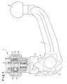
- the hitch 1 shown in Fig. 1 has a vertically extending Guide sleeve 2, which is attached to a cross member 3, the stationary on one Vehicle is arranged.
- the guide sleeve 2 serves to receive a removable ball neck 4 with a ball head 5 (in total also ball rod called), the ball neck 4 for insertion into the guide sleeve 2 an angled Introducer 6 has.
- As an end stop when inserting the ball neck 4 in the guide sleeve 2 and at the same time serve as an anti-rotation device two diametrically opposite, approximately triangular on both sides of the ball neck 4 Pin 7, which in complementary guide recesses 8 at the bottom Engage the end of the sleeve 2.
- a locking pin 10 is inserted, which is at a distance from upper, sealed by a screw cap 9 introducer is arranged and is formed at its lower end with a rack 11, which can be adjusted by means of a handwheel 12.
- the locking pin 10 is in the installed position axially acted upon by a compression spring 13 and acts on in the embodiment balls 15 inserted into radial bores 14 in the ball neck 4 - here there are three balls distributed around the circumference, which are connected with a spherical cap in corresponding cutouts 16 on the inner wall of the guide sleeve 2 arranged bearing ring 17 are pressed.
- the ball neck 4 locked in rotation with the guide sleeve 2 via its introducer 6.
- Balls could alternatively e.g. pins are also used as locking means, in the simplest case, a ball or a pin or the like is sufficient could be.
- the locking pin 10 has a secure locking a special geometry.
- the locking pin 10 consists of both Designs from an upper cone 18, an adjoining one upper cylinder 19, a middle cone 20 and a lower cylinder 21.
- Der middle cone 20 of the locking bolt 10 each has a cone angle of 3 ° on. Due to the smaller cone angle compared to conventional cone angles of 3 ° a higher self-locking is achieved in the locked state. Moreover a possible return movement of the locking pin 10 is caused of different loads on the ball head 5, reduced.
- FIG. 3 an embodiment of the locking pin 10 is shown, in which the upper Cylinder 19 with an undercut 25, here as a constriction or constriction Radius 23, based on the longitudinal axis of the locking pin 10 is formed.
- This makes the diameter in the transition region identical to the upper cylinder 19 reached to the middle cone 20.
- the upper cylindrical area in combination with the constriction 23 limits a total return movement the locking pin 10, if the self-locking effect of the middle Not cone 20 at very high loads on ball neck 4 and ball head 5 is sufficient and the locking pin 10 by the application of force to the locking balls 15 moved down.
- Such a movement limitation will also achieved when the locking pin 10 according to the alternative shown in Figure 2 on the upper cylinder 19 as an undercut 25 with an opposite slope 22 is formed towards the middle cone 20.
- a lower cone 24 is formed with a cone angle greater than 3 °.
- the increase in the lower cone angle towards the lower cylinder 21 enables an additional inhibition of the locking pin 10, causing a too wide Slipping of the locking pin 10 is prevented upwards. Still arises thus no play between the locking balls 15 and the locking pin 10th
- the length of the lower cone 24 can vary, cf. 2 and 3, so that each a sufficient adjustment travel of the Locking bolt 10 is guaranteed.
Abstract
Description
Die Erfindung betrifft eine Anhängevorrichtung für Kraftfahrzeuge wie PKW, LKW oder kleine Geländewagen, umfassend einen abnehmbaren, mit einem Kugelkopf und einem abgewinkelten Ende zum Einführen in eine fahrzeugfeste Führungshülse ausgebildeten Kugelhals, wobei das Einführende in Richtung seiner Längsachse einen zentralen Sperrbolzen aufnimmt, der einen Sperrbolzenkopf mit einem oberen Konus, einem sich daran nach unten anschließenden oberen Zylinder, einem mittleren Konus und einem unteren Zylinder aufweist, dessen mittlerer Konus zur Verriegelung auf mindestens ein im Kugelhals angeordnetes Rastmittel einwirkt, so daß dieses beim Eintauchen des Sperrbolzens teilweise ausgerückt wird und in eine korrespondierende Ausnehmung der Führungshülse eintritt.The invention relates to a hitch for motor vehicles such as cars, trucks or small off-road vehicles, including a removable one, with a spherical head and an angled end for insertion into a guide sleeve fixed to the vehicle trained ball neck, the introducer in the direction of its longitudinal axis a central locking pin that holds a locking pin head with a upper cone, an upper cylinder adjoining it downwards, has a central cone and a lower cylinder, the central one Cone for locking to at least one locking means arranged in the ball neck acts so that this partially disengaged when the locking bolt is immersed is and enters a corresponding recess of the guide sleeve.
Derartige Anhängevorrichtungen sind im Stand der Technik hinlänglich bekannt, beispielsweise aus der DE 29 35 474 C2. Damit man zu Zeiten, ohne Benutzung nicht ständig die mitunter beim Einparken störende Kugelstange (Kugelhals mit dem Kopf und dem Einführende) der Anhängevorrichtung außen am Fahrzeug mitführen muß, ist diese abnehmbar ausgeführt. Der am Fahrzeug verbleibende Teil der Anhängevorrichtung mit dem Verriegelungsmechanismus ist meist so angeordnet, daß er von außen nicht mehr sichtbar ist oder von einer Abdeckplatte verschlossen wird.Such hitching devices are well known in the prior art, for example from DE 29 35 474 C2. So that at times without use the ball rod (ball neck with the head and the introducer) of the towbar on the outside of the vehicle must be carried, this is designed to be removable. The one remaining on the vehicle Part of the hitch with the locking mechanism is usually arranged that it is no longer visible from the outside or from a cover plate is closed.
Wenn dann z.B. ein Anhänger angekoppelt werden soll, ist zur Verriegelung der Kugelstange mit der Führungshülse in dem Kugelhals ein über beispielsweise Federn oder Stößel beaufschlagbarer Sperrbolzen integriert. Nachdem der Kugelhals mit dem Sperrbolzen in die an der fahrzeugfesten Verriegelungseinrichtung angeordnete Führungshülse eingeschoben wurde, werden von dem Sperrbolzen in Bohrungen des Kugelhalses eingesetzte Kugeln beaufschlagt, so daß diese teilweise aus den Bohrungen aus- und in korrespondierende Aussparungen in der Innenwand der Führungshülse eintreten, womit der Kugelhals mit der Führungshülse verriegelt wird.Then if e.g. a trailer to be coupled is to lock the Ball rod with the guide sleeve in the ball neck over, for example, springs or tappet with integrated locking pin. After the ball neck with the locking pin in the arranged on the vehicle-specific locking device Guide sleeve has been pushed in by the locking pin Bores of the ball neck loaded balls, so that these partially out of the holes and into corresponding recesses in the Enter the inner wall of the guide sleeve, with which the ball neck with the guide sleeve is locked.
Zur Kraftbeaufschlagung der Verriegelungskugeln weist der Sperrbolzen eine bestimmte Geometrie auf. Die für die Verriegelung wichtigen Bereiche sind hierbei der obere Zylinder und der mittlere Konus. Der obere zylindrische Bereich soll hierbei eine axiale Rückstellbewegung des Sperrbolzens verhindern, falls die selbsthemmende Wirkung des mittleren Konus nicht mehr ausreicht und sich der Sperrbolzenkopf durch die Kraftbeaufschlagung der Verriegelungskugeln nach unten bewegt.The locking bolt has a specific one to apply force to the locking balls Geometry on. The areas important for locking are here the top cylinder and the middle cone. The upper cylindrical area should prevent an axial return movement of the locking pin if the self-locking effect of the middle cone is no longer sufficient and the Locking pin head by applying force to the locking balls moved down.
Der Erfindung liegt die Aufgabe zugrunde, eine gattungsgemäße Anhängevorrichtung mit Verriegelungseinrichtung zu schaffen, die eine Rückstellbewegung des Sperrbolzens begrenzt bzw. weitestgehend verringert.The invention has for its object a generic hitch with locking device to create a return movement of the locking pin limited or largely reduced.
Diese Aufgabe wird erfindungsgemäß dadurch gelöst, daß der obere Zylinder mit einem Hinterschnitt bzw. einer Hinterschneidung versehen ist. Damit wird ein sich zurückbewegender Sperrbolzen von dem bzw. den in die Hinterschneidung eingreifenden Rastmitteln gebremst und daran gehindert, übermäßig weit herunterzufallen, was natürlich durch das Zusammenwirken mit den Konusabschnitten aufgrund deren Selbsthemmung unterstützt wird.This object is achieved in that the upper cylinder with an undercut or an undercut is provided. So that becomes a Retracting locking bolt from the one or those engaging in the undercut Locking devices are braked and prevented from falling excessively far, which of course by interacting with the cone sections because of their self-locking is supported.
Eine bevorzugte Ausführung der Erfindung sieht vor, daß der obere Zylinder mit einem einschnürenden Radius, bezogen auf die Längsachse des Sperrbolzens, als Hinterschneidung ausgebildet ist. Aufgrund der Taillierung dieser Einschnürung im Übergang zwischen dem zylindrischen Bereich und dem mittleren Konus wird ein identischer Durchmesser für das zylindrische Ende und den konischen Anfang des Sperrbolzens erreicht, d.h. eine Parallelverschiebung nach außen. Damit läßt sich die Rückstellbewegung des Sperrbolzens im Verriegelungsmechanismus auf ein Minimum reduzieren.A preferred embodiment of the invention provides that the upper cylinder with a constricting radius, based on the longitudinal axis of the locking bolt, is designed as an undercut. Due to the waist of this constriction in the transition between the cylindrical area and the middle The cone becomes an identical diameter for the cylindrical end and the conical Start of the locking pin reached, i.e. a parallel shift to the outside. This allows the return movement of the locking pin in the locking mechanism reduce to a minimum.
Gemäß einer alternativen Ausführung ist es gleichwohl möglich, daß der obere Zylinder mit einer gegenläufigen Schräge hin zum mittleren Konus versehen ist.According to an alternative embodiment, it is nevertheless possible that the upper Cylinder is provided with an opposite slope towards the middle cone.
Beide geometrischen Varianten des Sperrbolzens ermöglichen die Begrenzung der Rückstellbewegung im Verriegelungsmechanismus, welche aufgrund von starken Lastwechseln bei großen Anhängelasten noch begünstigt wird, weil die Hinterschneidung den Sperrbolzen bremst, so daß dieser auf keinen Fall schlagartig seine Position verändern kann.Both geometrical variants of the locking pin allow the limitation the return movement in the locking mechanism, which due to strong load changes with large trailer loads is still favored because the Undercut brakes the locking pin so that it never suddenly can change its position.
Weitere Merkmale und Vorteile der Erfindung ergeben sich aus den Ansprüchen und der nachfolgenden Beschreibung von in den Zeichnungen dargestellten Ausführungsbeispielen der Erfindung. Es zeigen:
- Fig. 1
- einen Teilschnitt durch eine Verriegelungseinrichtung einer Anhängevorrichtung;
- Fig. 2
- einen Sperrbolzen der Verriegelungseinrichtung in der Seitenansicht dargestellt; und
- Fig. 3
- eine weitere Ausführung eines Sperrbolzens in der Seitenansicht dargestellt.
- Fig. 1
- a partial section through a locking device of a hitch;
- Fig. 2
- a locking pin of the locking device shown in side view; and
- Fig. 3
- another version of a locking pin shown in side view.
Die in Fig. 1 dargestellte Anhängevorrichtung 1 weist eine vertikal verlaufende
Führungshülse 2 auf, die an einem Querträger 3 befestigt ist, der ortsfest an einem
Fahrzeug angeordnet wird. Die Führungshülse 2 dient zur Aufnahme eines
abnehmbaren Kugelhalses 4 mit einem Kugelkopf 5 (insgesamt auch Kugelstange
genannt), wobei der Kugelhals 4 zum Einführen in die Führungshülse 2 ein abgewinkeltes
Einführende 6 aufweist. Als Endanschlag beim Einschieben des Kugelhalses
4 in die Führungshülse 2 und gleichzeitig als Verdrehsicherung dienen zwei
sich an beiden Seiten des Kugelhalses 4 diametral gegenüberliegende, etwa dreieckige
Zapfen 7, die in komplementäre Führungsausnehmungen 8 am unteren
Ende der Hülse 2 eingreifen.The
In das Einführende 6 wird ein Sperrbolzen 10 eingesetzt, der mit Abstand zum
oberen, von einer Einschraubkappe 9 verschlossenen Einführende angeordnet ist
und an seinem unteren Ende mit einer Zahnstange 11 ausgebildet ist, die sich
mittels eines Handrades 12 verstellen läßt. Der Sperrbolzen 10 wird in der Einbaulage
von einer Druckfeder 13 axial beaufschlagt und wirkt auf im Ausführungsbeispiel
in radiale Bohrungen 14 im Kugelhals 4 eingesetzte Kugeln 15 ein - hier
sind umfangsverteilt drei Kugeln vorgesehen -, die so mit einer Kugelkalotte in
entsprechende Aussparungen 16 eines an der Innenwand der Führungshülse 2
angeordneten Lagerringes 17 gedrückt werden. Dadurch wird der Kugelhals 4
über sein Einführende 6 verdrehsicher mit der Führungshülse 2 verriegelt. Statt
Kugeln könnten alternativ z.B. auch Stifte als Verriegelungsmittel eingesetzt werden,
wobei im einfachsten Fall eine Kugel bzw. ein Stift oder dergleichen ausreichend
sein könnte.In the introducer 6, a
Wie sich aus den Fig. 2 und 3 ergibt, weist der Sperrbolzen 10 zum sicheren Verriegeln
eine spezielle Geometrie auf. Der Sperrbolzen 10 besteht gemäß beiden
Ausführungen aus einem oberen Konus 18, einem sich daran anschließenden
oberen Zylinder 19, einem mittleren Konus 20 und einem unteren Zylinder 21. Der
mittlere Konus 20 des Sperrbolzens 10 weist jeweils einen Konuswinkel von 3°
auf. Durch den gegenüber bisher üblichen Konuswinkeln kleineren Konuswinkel
von 3° wird im verriegelten Zustand eine höhere Selbsthemmung erzielt. Außerdem
wird eine mögliche Rückstellbewegung des Sperrbolzens 10, hervorgerufen
von unterschiedlichen Belastungen am Kugelkopf 5, verringert.2 and 3, the
In Fig. 3 ist eine Ausführung des Sperrbolzens 10 dargestellt, bei der der obere
Zylinder 19 mit einem Hinterschnitt 25, hier als Einschnürung bzw. einschnürender
Radius 23, bezogen auf die Längsachse des Sperrbolzens 10 ausgebildet ist.
Damit wird ein zu dem oberen Zylinder 19 identischer Durchmesser im Übergangsbereich
zum mittleren Konus 20 erreicht. Der obere zylindrische Bereich
begrenzt im Zusammenspiel mit der Einschnürung 23 insgesamt eine Rückstellbewegung
des Sperrbolzens 10, falls die selbsthemmende Wirkung des mittleren
Konus 20 bei sehr hohen Belastungen am Kugelhals 4 und dem Kugelkopf 5 nicht
ausreicht und sich der Sperrbolzen 10 durch die Kraftbeaufschlagung der Verriegelungskugeln
15 nach unten bewegt. Eine solche Bewegungsbegrenzung wird
auch erreicht, wenn der Sperrbolzen 10 gemäß der in Figur 2 gezeigten Alternative
am oberen Zylinder 19 als Hinterschnitt 25 mit einer gegenläufigen Schräge 22
hin zum mittleren Konus 20 ausgebildet ist.In Fig. 3, an embodiment of the
Weiterhin ist an den Sperrbolzen 10 zwischen dem mittleren Konus 20 und dem
unteren Zylinder 21 ein unterer Konus 24 mit einem Konuswinkel größer 3° ausgebildet.
Der Anstieg des unteren Konuswinkels hin zum unteren Zylinder 21 ermöglicht
eine zusätzliche Hemmung des Sperrbolzens 10, wodurch ein zu weites
Durchrutschen des Sperrbolzens 10 nach oben hin verhindert wird. Weiterhin entsteht
somit auch kein Spiel zwischen den Verriegelungskugeln 15 und dem Sperrbolzen
10.Furthermore, is on the
Die Länge des unteren Konus 24 kann variieren, vgl. hierzu Fig. 2 und 3, so daß je
nach Belastungsfall im Anhängerbetrieb ein ausreichend großer Nachstellweg des
Sperrbolzens 10 gewährleistet wird.The length of the
Claims (3)
dadurch gekennzeichnet, daß der obere Zylinder (19) mit einer Hinterschneidung (25) versehen ist.Towing device (1) for motor vehicles, comprising a removable ball neck (4) designed with a ball head (5) and an angled end for insertion into a guide sleeve (2) fixed to the vehicle, the introducer (6) having a central locking pin () in the direction of its longitudinal axis. 10) which has a locking pin head with an upper cone (18), an upper cylinder (19) adjoining it downwards, a central cone (20) and a lower cylinder (21), the central cone (20) for locking acts on at least one locking means (15) arranged in the ball neck (4), so that when the locking bolt (10) is immersed it is partially disengaged and enters a corresponding recess (16) in the guide sleeve (2),
characterized in that the upper cylinder (19) is provided with an undercut (25).
dadurch gekennzeichnet, daß der obere Zylinder (19) mit einer Einschnürung (23) ausgebildet ist.Trailer hitch according to claim 1,
characterized in that the upper cylinder (19) is formed with a constriction (23).
dadurch gekennzeichnet, daß der obere Zylinder (19) mit einer gegenläufigen Schräge (22) hin zum mittleren Konus (20) versehen ist.Trailer hitch according to claim 1,
characterized in that the upper cylinder (19) is provided with an opposite slope (22) towards the central cone (20).
Applications Claiming Priority (2)
| Application Number | Priority Date | Filing Date | Title |
|---|---|---|---|
| DE20120531U | 2001-12-19 | ||
| DE20120531U DE20120531U1 (en) | 2001-12-19 | 2001-12-19 | Trailer device for motor vehicles |
Publications (2)
| Publication Number | Publication Date |
|---|---|
| EP1321317A1 true EP1321317A1 (en) | 2003-06-25 |
| EP1321317B1 EP1321317B1 (en) | 2007-04-18 |
Family
ID=7965351
Family Applications (1)
| Application Number | Title | Priority Date | Filing Date |
|---|---|---|---|
| EP02025841A Expired - Lifetime EP1321317B1 (en) | 2001-12-19 | 2002-11-19 | Trailer hitch for motor vehicles |
Country Status (3)
| Country | Link |
|---|---|
| EP (1) | EP1321317B1 (en) |
| AT (1) | ATE359925T1 (en) |
| DE (2) | DE20120531U1 (en) |
Cited By (5)
| Publication number | Priority date | Publication date | Assignee | Title |
|---|---|---|---|---|
| EP1829716A1 (en) | 2006-03-01 | 2007-09-05 | WESTFALIA - Automotive GmbH | Tow bar for motor vehicles |
| DE102007041582A1 (en) | 2007-09-01 | 2009-03-05 | Westfalia-Automotive Gmbh | Towing |
| EP2130696A1 (en) | 2008-06-06 | 2009-12-09 | WESTFALIA - Automotive GmbH | Trailer coupling with a sensor |
| EP2130700A1 (en) | 2008-06-06 | 2009-12-09 | WESTFALIA - Automotive GmbH | Coupling arm for a trailer coupling |
| DE102008034846A1 (en) | 2008-06-06 | 2009-12-17 | Westfalia-Automotive Gmbh | Holder for a coupling arm of a trailer hitch |
Families Citing this family (3)
| Publication number | Priority date | Publication date | Assignee | Title |
|---|---|---|---|---|
| DE102009018017A1 (en) | 2009-04-18 | 2010-10-21 | Fac Frank Abels Consulting & Technology Gesellschaft Mbh | Towing device for motor vehicle, has coupling ball carrier demountable from vehicle, where coupling ball carrier carries coupling ball at one end and has insertion section at opposite end |
| DE102009018019A1 (en) | 2009-04-18 | 2010-10-21 | Fac Frank Abels Consulting & Technology Gesellschaft Mbh | Towing device for motor vehicle, has coupling ball carrier demountable from vehicle, where coupling ball carrier carries coupling ball at one end and has insertion section at opposite end |
| DE102009018018A1 (en) | 2009-04-18 | 2010-10-21 | Fac Frank Abels Consulting & Technology Gesellschaft Mbh | Tow-bar for use in motor vehicle, has insertion section lockable sleeve by locking element, which is radially movable opposite to axis of insertion section, in insertion position, where locking element is lockable by hand-operable lever |
Citations (6)
| Publication number | Priority date | Publication date | Assignee | Title |
|---|---|---|---|---|
| DE2822662A1 (en) * | 1978-05-24 | 1979-11-29 | Eberhardt Peka Fahrzeug | Demountable towing hook for car - has profiled shaft and lateral clamping straps locked by eccentric rod |
| DE2935474C2 (en) | 1979-09-01 | 1982-04-29 | Daimler-Benz Ag, 7000 Stuttgart | Towing device, in particular for passenger cars. |
| DE3541904A1 (en) * | 1985-11-27 | 1987-06-04 | Daimler Benz Ag | Trailer coupling for vehicles |
| DE3601505A1 (en) * | 1986-01-20 | 1987-07-23 | Juergens Walter | Towing device |
| EP0593983A1 (en) * | 1992-10-23 | 1994-04-27 | MVG METALLVERARBEITUNGSGESELLSCHAFT mbH | Trailer coupling |
| EP1184212A2 (en) * | 2000-09-02 | 2002-03-06 | MVG METALLVERARBEITUNGSGESELLSCHAFT mbH | Trailer coupling |
-
2001
- 2001-12-19 DE DE20120531U patent/DE20120531U1/en not_active Expired - Lifetime
-
2002
- 2002-11-19 DE DE50209965T patent/DE50209965D1/en not_active Expired - Lifetime
- 2002-11-19 EP EP02025841A patent/EP1321317B1/en not_active Expired - Lifetime
- 2002-11-19 AT AT02025841T patent/ATE359925T1/en not_active IP Right Cessation
Patent Citations (6)
| Publication number | Priority date | Publication date | Assignee | Title |
|---|---|---|---|---|
| DE2822662A1 (en) * | 1978-05-24 | 1979-11-29 | Eberhardt Peka Fahrzeug | Demountable towing hook for car - has profiled shaft and lateral clamping straps locked by eccentric rod |
| DE2935474C2 (en) | 1979-09-01 | 1982-04-29 | Daimler-Benz Ag, 7000 Stuttgart | Towing device, in particular for passenger cars. |
| DE3541904A1 (en) * | 1985-11-27 | 1987-06-04 | Daimler Benz Ag | Trailer coupling for vehicles |
| DE3601505A1 (en) * | 1986-01-20 | 1987-07-23 | Juergens Walter | Towing device |
| EP0593983A1 (en) * | 1992-10-23 | 1994-04-27 | MVG METALLVERARBEITUNGSGESELLSCHAFT mbH | Trailer coupling |
| EP1184212A2 (en) * | 2000-09-02 | 2002-03-06 | MVG METALLVERARBEITUNGSGESELLSCHAFT mbH | Trailer coupling |
Cited By (9)
| Publication number | Priority date | Publication date | Assignee | Title |
|---|---|---|---|---|
| EP1829716A1 (en) | 2006-03-01 | 2007-09-05 | WESTFALIA - Automotive GmbH | Tow bar for motor vehicles |
| DE102007041582A1 (en) | 2007-09-01 | 2009-03-05 | Westfalia-Automotive Gmbh | Towing |
| EP2042353A1 (en) | 2007-09-01 | 2009-04-01 | WESTFALIA - Automotive GmbH | Trailer coupling |
| EP2130696A1 (en) | 2008-06-06 | 2009-12-09 | WESTFALIA - Automotive GmbH | Trailer coupling with a sensor |
| EP2130700A1 (en) | 2008-06-06 | 2009-12-09 | WESTFALIA - Automotive GmbH | Coupling arm for a trailer coupling |
| DE102008034853A1 (en) | 2008-06-06 | 2009-12-17 | Westfalia-Automotive Gmbh | Clutch arm for a trailer hitch |
| DE102008034846A1 (en) | 2008-06-06 | 2009-12-17 | Westfalia-Automotive Gmbh | Holder for a coupling arm of a trailer hitch |
| DE102008034850A1 (en) | 2008-06-06 | 2009-12-17 | Westfalia-Automotive Gmbh | Trailer coupling with a sensor |
| DE102008034846B4 (en) * | 2008-06-06 | 2015-02-12 | Westfalia-Automotive Gmbh | Holder for a coupling arm of a trailer hitch |
Also Published As
| Publication number | Publication date |
|---|---|
| DE20120531U1 (en) | 2002-05-23 |
| EP1321317B1 (en) | 2007-04-18 |
| DE50209965D1 (en) | 2007-05-31 |
| ATE359925T1 (en) | 2007-05-15 |
Similar Documents
| Publication | Publication Date | Title |
|---|---|---|
| EP0413197B1 (en) | Castor for platforms, scaffoldings or similar | |
| EP1475253A1 (en) | Trailer coupling for motor vehicles | |
| EP1829716B1 (en) | Tow bar for motor vehicles | |
| EP1321317B1 (en) | Trailer hitch for motor vehicles | |
| EP0789986B1 (en) | Tractor hitch lift link | |
| EP1321316B1 (en) | Trailer hitch for motor vehicles | |
| WO1997037862A1 (en) | Towing device | |
| DE2161580B2 (en) | Damper for tow-bar height control - has sprung braking wedge acting between conical pressure element and retaining plate | |
| DE4412088B4 (en) | trailer hitch | |
| EP0875439B1 (en) | Tensioning and clamping device | |
| DE19748117C2 (en) | ball pin | |
| DE69812317T2 (en) | Steering system, steering wheel and steering column for such a system | |
| DE19812472C2 (en) | Lifting device for lifting heavy loads, especially derailed rail vehicles | |
| EP1069020B1 (en) | Traction device for railway vehicles | |
| DE3419322A1 (en) | Disconnectable trailer coupling for motor vehicles | |
| DE19905299B4 (en) | Arrangement with trunnions | |
| EP0965466A1 (en) | Gimbal trailer coupling | |
| DE202019104457U1 (en) | Holder housing for a door stay and door stay | |
| DE4238590C2 (en) | Support device for a loading platform of a vehicle | |
| DE3625676A1 (en) | Axial overload element | |
| DE19736508C2 (en) | Closure for the detachable connection of two components | |
| DE10043339A1 (en) | Towing | |
| EP4108481A1 (en) | Towing device | |
| EP3486129A1 (en) | Support | |
| EP0213284A2 (en) | Mounting of the coupling element of a trailer draw-gear in the cross-member |
Legal Events
| Date | Code | Title | Description |
|---|---|---|---|
| PUAI | Public reference made under article 153(3) epc to a published international application that has entered the european phase |
Free format text: ORIGINAL CODE: 0009012 |
|
| AK | Designated contracting states |
Designated state(s): AT BE BG CH CY CZ DE DK EE ES FI FR GB GR IE IT LI LU MC NL PT SE SK TR |
|
| AX | Request for extension of the european patent |
Extension state: AL LT LV MK RO SI |
|
| 17P | Request for examination filed |
Effective date: 20031206 |
|
| AKX | Designation fees paid |
Designated state(s): AT BE BG CH CY CZ DE DK EE ES FI FR GB GR IE IT LI LU MC NL PT SE SK TR |
|
| RAP1 | Party data changed (applicant data changed or rights of an application transferred) |
Owner name: WESTFALIA - AUTOMOTIVE GMBH |
|
| GRAP | Despatch of communication of intention to grant a patent |
Free format text: ORIGINAL CODE: EPIDOSNIGR1 |
|
| GRAS | Grant fee paid |
Free format text: ORIGINAL CODE: EPIDOSNIGR3 |
|
| GRAA | (expected) grant |
Free format text: ORIGINAL CODE: 0009210 |
|
| AK | Designated contracting states |
Kind code of ref document: B1 Designated state(s): AT BE BG CH CY CZ DE DK EE ES FI FR GB GR IE IT LI LU MC NL PT SE SK TR |
|
| PG25 | Lapsed in a contracting state [announced via postgrant information from national office to epo] |
Ref country code: FI Free format text: LAPSE BECAUSE OF FAILURE TO SUBMIT A TRANSLATION OF THE DESCRIPTION OR TO PAY THE FEE WITHIN THE PRESCRIBED TIME-LIMIT Effective date: 20070418 |
|
| REG | Reference to a national code |
Ref country code: CH Ref legal event code: EP |
|
| REG | Reference to a national code |
Ref country code: IE Ref legal event code: FG4D Free format text: LANGUAGE OF EP DOCUMENT: GERMAN |
|
| REF | Corresponds to: |
Ref document number: 50209965 Country of ref document: DE Date of ref document: 20070531 Kind code of ref document: P |
|
| PG25 | Lapsed in a contracting state [announced via postgrant information from national office to epo] |
Ref country code: SE Free format text: LAPSE BECAUSE OF FAILURE TO SUBMIT A TRANSLATION OF THE DESCRIPTION OR TO PAY THE FEE WITHIN THE PRESCRIBED TIME-LIMIT Effective date: 20070718 |
|
| PG25 | Lapsed in a contracting state [announced via postgrant information from national office to epo] |
Ref country code: ES Free format text: LAPSE BECAUSE OF FAILURE TO SUBMIT A TRANSLATION OF THE DESCRIPTION OR TO PAY THE FEE WITHIN THE PRESCRIBED TIME-LIMIT Effective date: 20070729 |
|
| PG25 | Lapsed in a contracting state [announced via postgrant information from national office to epo] |
Ref country code: PT Free format text: LAPSE BECAUSE OF FAILURE TO SUBMIT A TRANSLATION OF THE DESCRIPTION OR TO PAY THE FEE WITHIN THE PRESCRIBED TIME-LIMIT Effective date: 20070918 |
|
| NLV1 | Nl: lapsed or annulled due to failure to fulfill the requirements of art. 29p and 29m of the patents act | ||
| ET | Fr: translation filed | ||
| GBV | Gb: ep patent (uk) treated as always having been void in accordance with gb section 77(7)/1977 [no translation filed] |
Effective date: 20070418 |
|
| REG | Reference to a national code |
Ref country code: IE Ref legal event code: FD4D |
|
| PG25 | Lapsed in a contracting state [announced via postgrant information from national office to epo] |
Ref country code: NL Free format text: LAPSE BECAUSE OF FAILURE TO SUBMIT A TRANSLATION OF THE DESCRIPTION OR TO PAY THE FEE WITHIN THE PRESCRIBED TIME-LIMIT Effective date: 20070418 Ref country code: BG Free format text: LAPSE BECAUSE OF FAILURE TO SUBMIT A TRANSLATION OF THE DESCRIPTION OR TO PAY THE FEE WITHIN THE PRESCRIBED TIME-LIMIT Effective date: 20070718 Ref country code: IE Free format text: LAPSE BECAUSE OF FAILURE TO SUBMIT A TRANSLATION OF THE DESCRIPTION OR TO PAY THE FEE WITHIN THE PRESCRIBED TIME-LIMIT Effective date: 20070418 Ref country code: DK Free format text: LAPSE BECAUSE OF FAILURE TO SUBMIT A TRANSLATION OF THE DESCRIPTION OR TO PAY THE FEE WITHIN THE PRESCRIBED TIME-LIMIT Effective date: 20070418 Ref country code: CZ Free format text: LAPSE BECAUSE OF FAILURE TO SUBMIT A TRANSLATION OF THE DESCRIPTION OR TO PAY THE FEE WITHIN THE PRESCRIBED TIME-LIMIT Effective date: 20070418 |
|
| PLBE | No opposition filed within time limit |
Free format text: ORIGINAL CODE: 0009261 |
|
| STAA | Information on the status of an ep patent application or granted ep patent |
Free format text: STATUS: NO OPPOSITION FILED WITHIN TIME LIMIT |
|
| PG25 | Lapsed in a contracting state [announced via postgrant information from national office to epo] |
Ref country code: SK Free format text: LAPSE BECAUSE OF FAILURE TO SUBMIT A TRANSLATION OF THE DESCRIPTION OR TO PAY THE FEE WITHIN THE PRESCRIBED TIME-LIMIT Effective date: 20070418 |
|
| 26N | No opposition filed |
Effective date: 20080121 |
|
| PG25 | Lapsed in a contracting state [announced via postgrant information from national office to epo] |
Ref country code: IT Free format text: LAPSE BECAUSE OF FAILURE TO SUBMIT A TRANSLATION OF THE DESCRIPTION OR TO PAY THE FEE WITHIN THE PRESCRIBED TIME-LIMIT Effective date: 20070418 Ref country code: GB Free format text: LAPSE BECAUSE OF FAILURE TO SUBMIT A TRANSLATION OF THE DESCRIPTION OR TO PAY THE FEE WITHIN THE PRESCRIBED TIME-LIMIT Effective date: 20070418 Ref country code: GR Free format text: LAPSE BECAUSE OF FAILURE TO SUBMIT A TRANSLATION OF THE DESCRIPTION OR TO PAY THE FEE WITHIN THE PRESCRIBED TIME-LIMIT Effective date: 20070719 |
|
| BERE | Be: lapsed |
Owner name: WESTFALIA - AUTOMOTIVE G.M.B.H. Effective date: 20071130 |
|
| PG25 | Lapsed in a contracting state [announced via postgrant information from national office to epo] |
Ref country code: MC Free format text: LAPSE BECAUSE OF NON-PAYMENT OF DUE FEES Effective date: 20071130 |
|
| PG25 | Lapsed in a contracting state [announced via postgrant information from national office to epo] |
Ref country code: CH Free format text: LAPSE BECAUSE OF NON-PAYMENT OF DUE FEES Effective date: 20071130 Ref country code: LI Free format text: LAPSE BECAUSE OF NON-PAYMENT OF DUE FEES Effective date: 20071130 |
|
| REG | Reference to a national code |
Ref country code: CH Ref legal event code: PL |
|
| PG25 | Lapsed in a contracting state [announced via postgrant information from national office to epo] |
Ref country code: BE Free format text: LAPSE BECAUSE OF NON-PAYMENT OF DUE FEES Effective date: 20071130 |
|
| PG25 | Lapsed in a contracting state [announced via postgrant information from national office to epo] |
Ref country code: EE Free format text: LAPSE BECAUSE OF FAILURE TO SUBMIT A TRANSLATION OF THE DESCRIPTION OR TO PAY THE FEE WITHIN THE PRESCRIBED TIME-LIMIT Effective date: 20070418 |
|
| PG25 | Lapsed in a contracting state [announced via postgrant information from national office to epo] |
Ref country code: AT Free format text: LAPSE BECAUSE OF NON-PAYMENT OF DUE FEES Effective date: 20071119 |
|
| PG25 | Lapsed in a contracting state [announced via postgrant information from national office to epo] |
Ref country code: CY Free format text: LAPSE BECAUSE OF FAILURE TO SUBMIT A TRANSLATION OF THE DESCRIPTION OR TO PAY THE FEE WITHIN THE PRESCRIBED TIME-LIMIT Effective date: 20070418 |
|
| PG25 | Lapsed in a contracting state [announced via postgrant information from national office to epo] |
Ref country code: LU Free format text: LAPSE BECAUSE OF NON-PAYMENT OF DUE FEES Effective date: 20071119 |
|
| PG25 | Lapsed in a contracting state [announced via postgrant information from national office to epo] |
Ref country code: TR Free format text: LAPSE BECAUSE OF FAILURE TO SUBMIT A TRANSLATION OF THE DESCRIPTION OR TO PAY THE FEE WITHIN THE PRESCRIBED TIME-LIMIT Effective date: 20070418 |
|
| REG | Reference to a national code |
Ref country code: FR Ref legal event code: PLFP Year of fee payment: 14 |
|
| REG | Reference to a national code |
Ref country code: FR Ref legal event code: PLFP Year of fee payment: 15 |
|
| REG | Reference to a national code |
Ref country code: FR Ref legal event code: PLFP Year of fee payment: 16 |
|
| PGFP | Annual fee paid to national office [announced via postgrant information from national office to epo] |
Ref country code: FR Payment date: 20211119 Year of fee payment: 20 Ref country code: DE Payment date: 20210928 Year of fee payment: 20 |
|
| REG | Reference to a national code |
Ref country code: DE Ref legal event code: R071 Ref document number: 50209965 Country of ref document: DE |