EP1475253A1 - Trailer coupling for motor vehicles - Google Patents
Trailer coupling for motor vehicles Download PDFInfo
- Publication number
- EP1475253A1 EP1475253A1 EP04006028A EP04006028A EP1475253A1 EP 1475253 A1 EP1475253 A1 EP 1475253A1 EP 04006028 A EP04006028 A EP 04006028A EP 04006028 A EP04006028 A EP 04006028A EP 1475253 A1 EP1475253 A1 EP 1475253A1
- Authority
- EP
- European Patent Office
- Prior art keywords
- ball rod
- trailer coupling
- coupling according
- locking
- mounting flange
- Prior art date
- Legal status (The legal status is an assumption and is not a legal conclusion. Google has not performed a legal analysis and makes no representation as to the accuracy of the status listed.)
- Granted
Links
- 230000008878 coupling Effects 0.000 title claims description 41
- 238000010168 coupling process Methods 0.000 title claims description 41
- 238000005859 coupling reaction Methods 0.000 title claims description 41
- 238000006073 displacement reaction Methods 0.000 claims description 7
- 230000007246 mechanism Effects 0.000 claims description 4
- 229910052751 metal Inorganic materials 0.000 claims description 3
- 239000002184 metal Substances 0.000 claims description 3
- 230000006835 compression Effects 0.000 description 3
- 238000007906 compression Methods 0.000 description 3
- 230000000903 blocking effect Effects 0.000 description 2
- 230000005484 gravity Effects 0.000 description 2
- 238000000034 method Methods 0.000 description 2
- 230000008569 process Effects 0.000 description 2
- 230000002411 adverse Effects 0.000 description 1
- 229910052782 aluminium Inorganic materials 0.000 description 1
- XAGFODPZIPBFFR-UHFFFAOYSA-N aluminium Chemical compound [Al] XAGFODPZIPBFFR-UHFFFAOYSA-N 0.000 description 1
- 210000000988 bone and bone Anatomy 0.000 description 1
- 230000003993 interaction Effects 0.000 description 1
- 230000001960 triggered effect Effects 0.000 description 1
- 239000013585 weight reducing agent Substances 0.000 description 1
Images


Classifications
-
- B—PERFORMING OPERATIONS; TRANSPORTING
- B60—VEHICLES IN GENERAL
- B60D—VEHICLE CONNECTIONS
- B60D1/00—Traction couplings; Hitches; Draw-gear; Towing devices
- B60D1/01—Traction couplings or hitches characterised by their type
- B60D1/06—Ball-and-socket hitches, e.g. constructional details, auxiliary devices, their arrangement on the vehicle
-
- B—PERFORMING OPERATIONS; TRANSPORTING
- B60—VEHICLES IN GENERAL
- B60D—VEHICLE CONNECTIONS
- B60D1/00—Traction couplings; Hitches; Draw-gear; Towing devices
- B60D1/24—Traction couplings; Hitches; Draw-gear; Towing devices characterised by arrangements for particular functions
- B60D1/26—Traction couplings; Hitches; Draw-gear; Towing devices characterised by arrangements for particular functions for remote control, e.g. for releasing
-
- B—PERFORMING OPERATIONS; TRANSPORTING
- B60—VEHICLES IN GENERAL
- B60D—VEHICLE CONNECTIONS
- B60D1/00—Traction couplings; Hitches; Draw-gear; Towing devices
- B60D1/48—Traction couplings; Hitches; Draw-gear; Towing devices characterised by the mounting
- B60D1/54—Traction couplings; Hitches; Draw-gear; Towing devices characterised by the mounting collapsible or retractable when not in use, e.g. hide-away hitches
Definitions
- the invention relates to a trailer coupling for motor vehicles, comprising a fixed, swivel and axially displaceable ball rod, which carries a coupling ball at its free end and both in its Rest position as well as in their operating position via interlocking contours that can be brought into engagement on the one hand a ball rod bearing head and on the other hand one of these opposite mounting flange is rotatably fixed, the ball rod bearing head with a lock for the positive locking contours both in the Operating position and in the rest position of the ball rod is formed.
- a trailer coupling of this type has become known from DE 198 59 961 A1.
- the ball rod consisting of a ball neck and coupling ball as well as a bearing sleeve or ball rod bearing head, is both in the rest position, in which the ball rod is roughly transverse to the vehicle's longitudinal direction under the bumper is, as well as in the operating position, in which the ball rod is essentially located in the longitudinal direction of the vehicle, by means of the interlocking connections fixed in rotation.
- the form-fitting connections in the form of a toothing as well as counter teeth engage in the rotary end positions of the ball rod bearing head each other.
- An adjustable, the abutment supporting the bearing sleeve or the ball rod bearing head, which is arranged on a bearing pin like the ball rod bearing head via a mounting bracket or mounting flange on one with the vehicle connected cross tube is attached.
- the bearing sleeve supporting abutment In one axial position of the bearing sleeve supporting abutment are the form-fitting contours of bearing bolts and Bearing sleeve in engagement with each other so that the bearing sleeve and thus the ball rod cannot be rotated relative to the vehicle.
- the invention has for its object a generic trailer coupling to create a simple and safe adjustment and setting of the Ball rod in the rotary end positions enabled.
- the locking one against an existing force element via an externally operable pressure or Traction device resettable locking pin includes two parallel to each other provided radial planes are assigned locking means acting in opposite directions.
- the rear flange facing the mounting flange can be used Level in the rotary end positions of the ball rod reach their locking because the locking means pull the ball rod bearing head into this plane.
- the locking means of the front radial plane in this operating state for the Locking the form-locking contours ineffective are the locking means of the front radial plane in this operating state for the Locking the form-locking contours ineffective.
- a preferred embodiment of the invention provides that the ball rod bearing head is arranged on a hollow shaft which receives the locking pin centrally.
- a self-contained, achieve a largely maintenance-free system.
- the axial locking achieved in interaction with the two-level locking means leads to one simultaneous, automatic axial displacement of the ball rod as soon as the blocking is released in a rotary end position.
- the latching means are designed as balls and in radial bores the hollow shaft is arranged limited engaging and disengaging.
- the front end of the locking bolt is advantageous formed with a constriction section, the two ends with inclined surfaces on the one hand in the rear locking pin body and on the other hand the Lock bolt head passes.
- the diameter is reduced of the locking pin due to the constriction section the required Free space so that in this position the locking balls of the front level are turned inwards can fall.
- the caft element e.g. B. a compression spring, biased or contracted is, for example by means of a handwheel, as from DE-U 94 08 478.5 known, over which a rack a Bowden cable as a connection actuated to the locking pin so that the locking pin is withdrawn, the fall previously pushed apart balls of the rear level inwards, too here the constriction section in turn creates the necessary free space, while the balls of the front level from the locking pin now outwards be moved and with the force component imposed on them in the release direction support pushing the ball rod.
- a compression spring biased or contracted is, for example by means of a handwheel, as from DE-U 94 08 478.5 known, over which a rack a Bowden cable as a connection actuated to the locking pin so that the locking pin is withdrawn, the fall previously pushed apart balls of the rear level inwards, too here the constriction section in turn creates the necessary free space, while the balls of the front level from the locking pin now outwards be moved and with
- Ball rod or ball bearing head released from the mounting flange By withdrawing the locking pin from its positive connection Ball rod or ball bearing head released from the mounting flange can thus after unlocking under the force of gravity with simultaneous axial Swivel the displacement into an intermediate position. From there you can Ball rod manually or motor-operated in the desired, each by one Swivel and lock the outer stop secured rotary end position for what the force element allows relaxation, so that the locking pin advances and the locking balls of the rear radial plane reverse to the above Can push the drain back out into its locked position while the locking balls of the front level fall inwards again.
- mechanical Handwheel release is e.g. also a motorized trigger drive or the use of electric or lifting magnets possible, their axial movement can block another solenoid as a fuse. When actuating one The safety stroke magnet is first executed via a control and then the main magnet is released.
- the balls are in the ball rod bearing head with opposite bevels in the two radial planes trained recordings, e.g. an annular groove or groove, which is advantageous in one Have the bearing ring provided in the ball rod bearing head assigned.
- the Taper of the balls of the rear radial plane aligned with the mounting flange favors the automatic tightening of the ball rod bearing head during the locking process in the positive connection with the mounting flange, while conversely, the run-up slope of the front radial plane balls supports the triggering.
- a proposal of the invention is between that of the mounting flange distal end of the hollow shaft and a connecting plate provided there arranged a shim.
- the shim enables adjustment when installing the ball rod.
- Both the mounting flange as well the connecting plate, both for attaching the trailer coupling to one Cross member of the motor vehicle can be used as a simple laser or Stamped parts are manufactured. If the ball rod in the simplest case without that Connection plate and only connected to the cross member via the mounting flange is, the hollow shaft can be closed with a stopper or a cap; a This design does not require a shim.
- Cultivation variants of the invention provide that the connecting plate and / or the Mounting flange on a middle part of a multi-part cross member or off-center is or are attached to the cross member. Despite an off-center attachment of the In the operating position, the coupling rod is located in the center of the longitudinal direction of the vehicle.
- the ball rod can be pivoted assign the participating socket holder. This can be directly on the ball neck or on the ball rod bearing head itself or alternatively on the right or left of it are located.
- One for power supply for an advantageous motorized turning and Swivel drive of the ball rod serving, not directly on the ball rod provided socket holder can in this case during the pivoting movement appropriately attached driver cams from its rest position to the operating position to be brought.
- the retrieval can be done via a spring.
- At least some components of the trailer coupling according to the invention are made of light metal, e.g. made of aluminum or the like achieve a weight reduction.
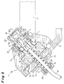
- a trailer coupling shown in FIGS. 1 and 2 is one or multi-part cross member attached to a vehicle (not shown).
- the trailer coupling comprises a cranked coupling ball at its free end 2 bearing ball rod 3, with its ball bearing head 4 between one Mounting flange 5 and in this embodiment with an interposition a shim 6 opposite connecting plate 7 is arranged is.
- the ball rod bearing head 4 is held by means of a Hollow shaft 8 (see FIGS. 3 to 5) on which the ball rod with its ball rod bearing head 4 is stored.
- a mounting bushing 9 is fitted from the outside of the mounting flange, the end part of the hub and with a bore 10 in alignment with the central Bore 11 of the hollow shaft 8 and a through hole of the mounting flange 5 is arranged trending.
- the mounting socket 9 could alternatively also be integrally formed with the hollow shaft 8, for. B. only as a hub extension of the collar 13 of the hollow shaft 8.
- the bore of the mounting flange 5 is overhanged by a flange 12 of the mounting bush 9.
- Through the flange 12 in provide a collar 13 of the hollow shaft 8 screwed fastening screws 14 for the exact positioning of the hollow shaft 8, which is furthermore due to Centering pins 15 is supported, and at the same time prevent displacement of the Hollow shaft 8.
- the hitch with its mounting flange 5 on one or multi-part cross member attached to a motor vehicle, not shown connected is.
- Fig. 1 shows that in the operating position and Fig. 2 that pivoted into the rest position Ball rod 3 of the trailer coupling 1.
- the Ball rod 3 locked non-rotatably (will be described below).
- a handwheel trigger mechanism 16 via a with a screw sleeve 17a connected to the hub of the mounting bush 9 Bowden cable 17, the end that dips into the ball rod ply head 4 with a locking pin 18 which can be moved back and forth in the hollow shaft 8 (cf. the 3 to 5) is connected.
- FIG. 3 is in the rotary end positions (operating or rest position) the ball rod 3 via a positive connection 19, which here in the mounting flange 5 arranged balls 20 and this in the end face of the Ball rod bearing head 4 there are oppositely assigned domes 21 (see FIG. 5), fixed in rotation.
- To lock these rotary end positions are for the locking pin 18 in a rear radial plane I in radial bores 22a, these are only partially recognizable in Fig. 3 because of the offset cutting plane Hollow shaft 8 a plurality of locking means in the form of balls 23a provided by the rear locking pin body 18a are pressed out and in one assigned to them in a bearing ring 24 of the ball rod bearing head 4 Recording 25a, formed for example as an annular groove or groove.
- the receptacle 25a is on its running surface facing the mounting flange 5 provided with a chamfer 26a (see also FIGS. 4 and 5), which in the the rotational end positions locked position of the ball rod 3 a targeted Force for the axial displacement of the ball rod 3 or the ball rod bearing head 4 in the direction of the mounting flange 5.
- the locking pin 18, which on its the balls 23a through the radial bores 22b into the receptacle 25a of the bearing ring 24, pressing its rear circumference Locking pin body 18a with a self-locking bevel 27 and / or an undercut is formed in this blocking position by a Force element in the form of a compression spring 28 moves in behind the locking pin the bores 11 and 10 of the hollow shaft 8, mounting flange 5 and mounting bush 9 is arranged.
- the locking pin 18 are in a second, front radial plane II in radial bores 22b of the hollow shaft 8 circumferentially distributed further locking means in Form of balls 23b and a receptacle 25b, again formed, for example assigned as an annular groove or groove.
- This front receptacle 25b is with a run-up slope 26b is formed, the one opposite to the run-up slope 26a of the front radial plane I aligned force, namely away from Mounting flange 5 causes.
- Towards the front is the trailer coupling 1 closed by a cap 29 screwed onto the free end of the hollow shaft 8.
- the locking pin 18 is actuated by actuating e.g. in one Trunk of a motor vehicle attached handwheel release mechanism 16 against the spring 28 (not shown in FIGS. 4 and 5 for the sake of simplicity), which prestresses, deferred; this retracted position of the locking pin 18 shows FIG. 4.
- actuating e.g. in one Trunk of a motor vehicle attached handwheel release mechanism 16 against the spring 28 (not shown in FIGS. 4 and 5 for the sake of simplicity), which prestresses, deferred; this retracted position of the locking pin 18 shows FIG. 4.
Abstract
Description
Die Erfindung betrifft eine Anhängekupplung für Kraftfahrzeuge, umfassend eine fahrzeugfest angeordnete, schwenkbar sowie axial verschieblich gelagerte Kugelstange, die an ihrem freien Ende eine Kupplungskugel trägt und sowohl in ihrer Ruhelage als auch in ihrer Betriebslage über in Eingriff bringbare Formschlußkonturen einerseits eines Kugelstangenlagerkopfes und andererseits eines diesem gegenüberliegenden Anbauflansches drehfest festlegbar ist, wobei der Kugelstangenlagerkopf mit einer Verriegelung für die Formschlußkonturen sowohl in der Betriebslage als auch in der Ruhelage der Kugelstange ausgebildet ist.The invention relates to a trailer coupling for motor vehicles, comprising a fixed, swivel and axially displaceable ball rod, which carries a coupling ball at its free end and both in its Rest position as well as in their operating position via interlocking contours that can be brought into engagement on the one hand a ball rod bearing head and on the other hand one of these opposite mounting flange is rotatably fixed, the ball rod bearing head with a lock for the positive locking contours both in the Operating position and in the rest position of the ball rod is formed.
Eine Anhängekupplung dieser Art ist durch die DE 198 59 961 A1 bekanntgeworden. Die Kugelstange, bestehend aus Kugelhals und Kupplungskugel sowie Lagerhülse bzw. Kugelstangenlagerkopf, wird sowohl in der Ruhelage, in welcher sich die Kugelstange in etwa quer zur Fahrzeuglängsrichtung unter dem Stoßfänger befindet, als auch in der Betriebslage, in welcher sich die Kugelstange im wesentlichen in Fahrzeuglängsrichtung befindet, mittels der Formschlußverbindungen drehfest festgelegt. Die Formschlußverbindungen in Form einer Verzahnung sowie einer Gegenverzahnung greifen in den Drehendstellungen des Kugelstangenlagerkopfes ineinander.A trailer coupling of this type has become known from DE 198 59 961 A1. The ball rod, consisting of a ball neck and coupling ball as well as a bearing sleeve or ball rod bearing head, is both in the rest position, in which the ball rod is roughly transverse to the vehicle's longitudinal direction under the bumper is, as well as in the operating position, in which the ball rod is essentially located in the longitudinal direction of the vehicle, by means of the interlocking connections fixed in rotation. The form-fitting connections in the form of a toothing as well as counter teeth engage in the rotary end positions of the ball rod bearing head each other.
Zum Festlegen und Freigeben dieser bekannten Kugelstange dient ein verstellbares, die Lagerhülse bzw. den Kugelstangenlagerkopf abstützendes Widerlager, das wie der Kugelstangenlagerkopf auf einem Lagerbolzen angeordnet ist, der über einen Befestigungsansatz bzw. Anbauflansch an einem mit dem Fahrzeug verbundenen Querrohr befestigt ist. In der einen Axialstellung des die Lagerhülse abstützenden Widerlagers stehen die Formschlußkonturen von Lagerbolzen und Lagerhülse so miteinander in Eingriff, daß die Lagerhülse und damit die Kugelstange gegenüber dem Fahrzeug nicht verdreht werden kann. In der zweiten Axialstellung, in der das Widerlager dann von dem Anbauflansch bzw. Befestigungsansatz entfernt ist, kann die Lagerhülse so weit von dem Anbauflansch des Lagerbolzens abgerückt werden, daß die Formschlußkonturen außer Eingriff kommen und danach die Lagerhülse samt daran angeordneter Kugelstange zwischen der Ruhe- und der Betriebslage verschwenkt werden kann. Die jeweilige Verriegelungsposition wird danach von Hand durch eine erneute Axialverschiebung des Widerlagers erreicht.An adjustable, the abutment supporting the bearing sleeve or the ball rod bearing head, which is arranged on a bearing pin like the ball rod bearing head via a mounting bracket or mounting flange on one with the vehicle connected cross tube is attached. In one axial position of the bearing sleeve supporting abutment are the form-fitting contours of bearing bolts and Bearing sleeve in engagement with each other so that the bearing sleeve and thus the ball rod cannot be rotated relative to the vehicle. In the second Axial position in which the abutment is then from the mounting flange or mounting boss is removed, the bearing sleeve as far from the mounting flange of the Bearing pin are moved away that the positive locking contours out of engagement come and then the bearing sleeve together with the ball rod arranged between the rest and operating position can be pivoted. The respective The locking position is then changed manually by another axial displacement of the abutment reached.
Der Erfindung liegt die Aufgabe zugrunde, eine gattungsgemäße Anhängekupplung zu schaffen, die ein einfaches sowie sicheres Verstellen und Festlegen der Kugelstange in den Drehendstellungen ermöglicht.The invention has for its object a generic trailer coupling to create a simple and safe adjustment and setting of the Ball rod in the rotary end positions enabled.
Diese Aufgabe wird erfindunggemäß dadurch gelöst, daß die Verriegelung einen gegen ein anstehendes Kraftelement über ein von außen betätigbares Druck- oder Zugmittel zurückstellbaren Sperrbolzen umfaßt, dem in zwei parallel voneinander vorgesehenen Radialebenen gegenläufig wirkende Rastmittel zugeordnet sind. Hierbei läßt sich mit ausschließlich der hinteren, dem Anbauflansch zugewandten Ebene in den Drehendlagen der Kugelstange deren Verriegelung erreichen, weil die Rastmittel den Kugelstangenlagerkopf in diese Ebene hineinziehen. Hingegen sind die Rastmittel der vorderen Radialebene in diesem Betriebszustand für die Verriegelung der Formschlußkonturen unwirksam. Beim Auslösen zum Verschwenken des Kugelstangenlagerkopfes unterstützen dann aber die Rastmittel der vorderen Radialebene das Abdrücken des Kugelstangenlagerkopfes aus seiner Formschlußverbindung mit dem Anbauflansch, weil die Rastmittel der vorderen Radialebene den Kugelstangenlagerkopf zusätzlich definiert in Löserichtung wegdrücken. Diese unterstützende Beaufschlagung des Kugelstangenlagerkopfes in Löserichtung gewährleistet, daß ein Ausrücken der Kugelstange auch bei tiefen Temperaturen oder bei Verschmutzung der Anhängekupplung, zumal wenn diese lange nicht benutzt und betätigt worden ist, mit dann möglicherweise in ihren Sitzen verbackenen Rastmitteln, möglich ist.This object is achieved according to the invention in that the locking one against an existing force element via an externally operable pressure or Traction device resettable locking pin includes two parallel to each other provided radial planes are assigned locking means acting in opposite directions. In this case, only the rear flange facing the mounting flange can be used Level in the rotary end positions of the ball rod reach their locking because the locking means pull the ball rod bearing head into this plane. On the other hand are the locking means of the front radial plane in this operating state for the Locking the form-locking contours ineffective. When triggered to pivot of the ball rod bearing head then support the locking means the front radial plane pushing the ball rod bearing head out of it Positive connection with the mounting flange because the locking means of the front Radial plane also defines the ball rod bearing head in the release direction Pushing away. This supports the ball bearing head in the release direction ensures that disengagement of the ball rod even at deep Temperatures or if the trailer coupling is dirty, especially if it is has not been used for a long time and may have been in their seats baked locking means is possible.
Eine bevorzugte Ausführung der Erfindung sieht vor, daß der Kugelstangenlagerkopf auf einer Hohlwelle angeordnet ist, die den Sperrbolzen zentral aufnimmt. Durch die Abkehr von einer auf einem Lagerbolzen bzw. einer durchgängigen Lagerachse gelagerten Kugelstange, die somit vielmehr auf einer Hohlwelle mit zentral integrierter Verriegelung angeordnet ist, läßt sich ein in sich geschlossenes, weitestgehend wartungsfreies System erreichen. Die erreichte axial wirkende Verriegelung im Zusammenspiel mit den Zwei-Ebenen-Rastmitteln führt zu einer gleichzeitigen, selbsttätigen axialen Zwangsverschiebung der Kugelstange, sobald die Sperrung in einer Drehendlage aufgehoben wird.A preferred embodiment of the invention provides that the ball rod bearing head is arranged on a hollow shaft which receives the locking pin centrally. By moving away from a bearing pin or a continuous bearing axis mounted ball rod, which is rather on a hollow shaft with central integrated lock is arranged, a self-contained, achieve a largely maintenance-free system. The axial locking achieved in interaction with the two-level locking means leads to one simultaneous, automatic axial displacement of the ball rod as soon as the blocking is released in a rotary end position.
Die Rastmittel sind in vorteilhafter Ausführung als Kugeln ausgebildet und in Radialbohrungen der Hohlwelle begrenzt ein- und ausrückbar angeordnet. In der Verriegelungsposition, die vorteilhaft durch eine selbsthemmende Schräge und/oder einen Hinterschnitt des Sperrbolzens zusätzlich gesichert werden kann, drückt der Sperrbolzen die Kugeln der hinteren Ebene in den Radialbohrungen nach außen, womit eine weitere axiale Verstellung der Kugelstange verhindert wird, während die Kugeln der vorderen Ebene sich in einer unwirksamen, nach innen gefallenen Position befinden. Zu diesem Zweck ist vorteilhaft das vordere Ende des Sperrbolzens mit einem Einschnürungsabschnitt ausgebildet, der beidendig mit Schrägflächen einerseits in den rückwärtigen Sperrbolzenkörper und andererseits den Sperrbolzenkopf übergeht. In dieser Ausführung schafft die Durchmesserverringerung des Sperrbolzens aufgrund des Einschnürungsabschnitts den erforderlichen Freiraum, damit in dieser Position die Rastkugeln der vorderen Ebene nach innen fallen können. In an advantageous embodiment, the latching means are designed as balls and in radial bores the hollow shaft is arranged limited engaging and disengaging. In the locked position, which is advantageous due to a self-locking bevel and / or an undercut of the locking pin can be additionally secured, the presses Locking pins the balls of the rear level in the radial holes to the outside, which prevents further axial displacement of the ball rod while the balls of the front level are in an ineffective, fallen inside Position. For this purpose, the front end of the locking bolt is advantageous formed with a constriction section, the two ends with inclined surfaces on the one hand in the rear locking pin body and on the other hand the Lock bolt head passes. In this version, the diameter is reduced of the locking pin due to the constriction section the required Free space so that in this position the locking balls of the front level are turned inwards can fall.
Wenn dann das Kaftelement, z. B. eine Druckfeder, vorgespannt bzw. zusammengezogen wird, beispielsweise mittels eines Handrades, wie aus der DE-U 94 08 478.5 bekannt, über das eine Zahnstange einen Bowdenzug als Verbindung zum Sperrbolzen betätigt, so daß der Sperrbolzen zurückgezogen wird, fallen die zuvor auseinandergedrückten Kugeln der hinteren Ebene nach innen, wobei auch hier der Einschnürungsabschnitt wiederum den notwendigen Freiraum schafft, während die Kugeln der vorderen Ebene von dem Sperrbolzen nunmehr nach außen bewegt werden und mit der ihnen in Löserichtung aufgezwungenen Kraftkomponente das Abdrücken der Kugelstange unterstützen.Then if the caft element, e.g. B. a compression spring, biased or contracted is, for example by means of a handwheel, as from DE-U 94 08 478.5 known, over which a rack a Bowden cable as a connection actuated to the locking pin so that the locking pin is withdrawn, the fall previously pushed apart balls of the rear level inwards, too here the constriction section in turn creates the necessary free space, while the balls of the front level from the locking pin now outwards be moved and with the force component imposed on them in the release direction support pushing the ball rod.
Die durch das Zurückziehen des Sperrbolzens aus ihrer Formschlußverbindung vom Anbauflansch freigekommene Kugelstange bzw. der Kugelstangenlagerkopf kann somit nach dem Entriegeln unter der Schwerkraft bei gleichzeitiger axialer Verschiebung in eine Zwischenposition schwenken. Aus der heraus läßt sich die Kugelstange manuell oder motorbetrieben in die gewünschte, jeweils durch einen äußeren Anschlag gesicherte Drehendlage verschwenken und verriegeln, wozu dem Kraftelement die Entspannung ermöglicht wird, so daß der Sperrbolzen vorrücken und die Rastkugeln der hinteren Radialebene umgekehrt zum vorbeschriebenen Ablauf wieder nach außen in ihre Einrastposition drücken kann, während die Rastkugeln der vorderen Ebene wieder nach innen fallen. Alternativ zur mechanischen Handrad-Auslösung ist z.B. auch ein motorischer Auslöseantrieb oder der Einsatz von Elektro- bzw. Hubmagneten möglich, deren axiale Bewegung ein weiterer Hubmagnet als Sicherung sperren kann. Bei einer Betätigung einer solchen Ausführung wird über eine Steuerung zunächst der Sicherungshubmagnet und anschließend der Hauptmagnet gelöst.By withdrawing the locking pin from its positive connection Ball rod or ball bearing head released from the mounting flange can thus after unlocking under the force of gravity with simultaneous axial Swivel the displacement into an intermediate position. From there you can Ball rod manually or motor-operated in the desired, each by one Swivel and lock the outer stop secured rotary end position for what the force element allows relaxation, so that the locking pin advances and the locking balls of the rear radial plane reverse to the above Can push the drain back out into its locked position while the locking balls of the front level fall inwards again. As an alternative to mechanical Handwheel release is e.g. also a motorized trigger drive or the use of electric or lifting magnets possible, their axial movement can block another solenoid as a fuse. When actuating one The safety stroke magnet is first executed via a control and then the main magnet is released.
Nach einer Ausgestaltung der Erfindung sind den Kugeln im Kugelstangenlagerkopf mit in den beiden Radialebenen gegenläufig ausgerichteten Anlaufschrägen ausgebildete Aufnahmen, z.B. eine Ringnut oder Rille, die sich vorteilhaft in einen im Kugelstangenlagerkopf befestigten Lagerring vorsehen lassen, zugeordnet. Die zum Anbauflansch ausgerichtete Anlaufschräge der Kugeln der hinteren Radialebene begünstigt beim Verriegelungsvorgang das automatische Anziehen des Kugelstangenlagerkopfes in die Formschlußverbindung mit dem Anbauflansch, während umgekehrt die Anlaufschräge der Aufnahme der Kugeln der vorderen Radialebene das Abdrücken unterstützt.According to one embodiment of the invention, the balls are in the ball rod bearing head with opposite bevels in the two radial planes trained recordings, e.g. an annular groove or groove, which is advantageous in one Have the bearing ring provided in the ball rod bearing head assigned. The Taper of the balls of the rear radial plane aligned with the mounting flange favors the automatic tightening of the ball rod bearing head during the locking process in the positive connection with the mounting flange, while conversely, the run-up slope of the front radial plane balls supports the triggering.
Erfindungsgemäß wird vorgeschlagen, daß zur Formschlußverbindung von Kugelstangenlagerkopf und Anbauflansch in deren einander gegenüberliegenden Stirnflächen auf gleichen Teilkreisen gleichmäßig verteilt einerseits Kugeln und andererseits Kalotten ausgebildet sind. Alternativ eignen sich Verzahnungen oder dergleichen Rastmittel, die in den Drehendlagen ineinandergreifen.According to the invention it is proposed that for the positive connection of the ball rod bearing head and mounting flange in their opposite end faces balls evenly distributed on the same pitch circles on the one hand and on the other hand Domes are formed. Alternatively, gears or the like are suitable Latching devices that interlock in the rotary end positions.
Nach einem Vorschlag der Erfindung ist zwischen dem von dem Anbauflansch entfernten Ende der Hohlwelle und einem dort vorgesehenen Verbindungsblech eine Ausgleichsscheibe angeordnet. Die Ausgleichsscheibe ermöglicht eine Anpassung bei der Montage der Kugelstange. Sowohl der Anbauflansch als auch das Verbindungsblech, beides zur Befestigung der Anhängekupplung an einen Querträger des Kraftfahrzeuges geeignet, können als einfache Laser- oder Stanzteile hergestellt werden. Wenn die Kugelstange im einfachsten Fall ohne das Verbindungsblech und nur über den Anbauflansch mit dem Querträger verbunden ist, läßt sich die Hohlwelle mit einem Stopfen bzw. einer Kappe verschließen; eine Ausgleichsscheibe ist bei dieser Bauweise nicht erforderlich.According to a proposal of the invention is between that of the mounting flange distal end of the hollow shaft and a connecting plate provided there arranged a shim. The shim enables adjustment when installing the ball rod. Both the mounting flange as well the connecting plate, both for attaching the trailer coupling to one Cross member of the motor vehicle can be used as a simple laser or Stamped parts are manufactured. If the ball rod in the simplest case without that Connection plate and only connected to the cross member via the mounting flange is, the hollow shaft can be closed with a stopper or a cap; a This design does not require a shim.
Anbauvarianten der Erfindung sehen vor, daß das Verbindungsblech und/oder der Anbauflansch an einem Mittelteil eines mehrteiligen Querträgers oder außermittig am Querträger befestigt ist bzw. sind. Trotz einer außermittigen Anbringung der Kugelstange befindet sich die Kupplungskugel in der Betriebslage mittig zur Fahrzeuglängsrichtung. Cultivation variants of the invention provide that the connecting plate and / or the Mounting flange on a middle part of a multi-part cross member or off-center is or are attached to the cross member. Despite an off-center attachment of the In the operating position, the coupling rod is located in the center of the longitudinal direction of the vehicle.
Der Kugelstange läßt sich weiterbildungsgemäß ein deren Schwenkbewegungen mitmachender Steckdosenhalter zuordnen. Dieser kann sich direkt am Kugelhals oder am Kugelstangenlagerkopf selbst bzw. wahlweise rechts oder links davon befinden. Ein zur Stromversorgung für einen vorteilhaften motorischen Dreh- und Schwenkantrieb der Kugelstange dienender, nicht unmittelbar an der Kugelstange vorgesehener Steckdosenhalter kann hierbei bei der Schwenkbewegung durch entsprechend angebrachte Mitnehmernocken von seiner Ruheposition in die Betriebsposition gebracht werden. Das Zurückholen kann über eine Feder erfolgen.According to a further development, the ball rod can be pivoted assign the participating socket holder. This can be directly on the ball neck or on the ball rod bearing head itself or alternatively on the right or left of it are located. One for power supply for an advantageous motorized turning and Swivel drive of the ball rod serving, not directly on the ball rod provided socket holder can in this case during the pivoting movement appropriately attached driver cams from its rest position to the operating position to be brought. The retrieval can be done via a spring.
Wenn zumindest einige Bauteile der Anhängekupplung erfindungsgemäß aus Leichtmetall gefertigt sind, z.B. aus Aluminium oder dergleichen bestehen, läßt sich eine Gewichtsreduzierung erreichen.If at least some components of the trailer coupling according to the invention Are made of light metal, e.g. made of aluminum or the like achieve a weight reduction.
Weiterhin wird vorgeschlagen, daß mechanisch stark belastete und beanspruchte Bereiche der Kupplungsbauteile, z.B. der Kugelstangenlagerkopf und/oder die Kalotten und/oder die Kupplungskugel, bzw. der Lagerring, die Radialbohrungen oder der Sperrbolzen, gehärtet oder zumindest bereichsweise mit einer härteren Schicht versehen sind, wie vor allem beim Einsatz von Leichtmetall-Bauteilen.It is also proposed that mechanically heavily loaded and stressed Areas of the coupling components, e.g. the ball rod bearing head and / or the Calottes and / or the coupling ball, or the bearing ring, the radial bores or the locking bolt, hardened or at least in some areas with a harder one Layer are provided, especially when using light metal components.
Weitere Merkmale und Einzelheiten der Erfindung ergeben sich aus den Ansprüchen und der nachfolgenden Beschreibung von in den Zeichnungen dargestellten Ausführungsbeispielen der Erfindung. Es zeigen:
- Fig. 1
- in einer perspektivischen Gesamtansicht eine Anhängekupplung, umfassend einen Anbauflansch und ein Verbindungsblech, mit in ihrer Betriebslage verriegelter, sich mittig in Längsrichtung eines nicht dargestellten Fahrzeugs erstreckender Kugelstange, angeschlossen an einen Handrad-Auslösemechanismus;
- Fig. 2
- die Anhängekupplung nach Fig. 1 in vergrößerter perspektivischer Darstellung mit in ihrer Ruhelage verriegelter Kugelstange, in der sich diese unter einem Stoßfänger des nicht gezeigten Kraftfahrzeugs befindet;
- Fig. 3
- die Anhängekupplung nach Fig. 2, allerdings in einer Ausführung ohne ein vorne angeordnetes Verbindungsblech, in einem Längsschnitt mit versetzter Schnittebene, in der Verriegelungsposition dargestellt;
- Fig. 4
- die Anhängekupplung nach Fig. 3 in einer Position zum Auslöse- bzw. Abdrückvorgang dargestellt; und
- Fig. 5
- die Anhängekupplung nach Fig. 3 bzw. Fig. 4 mit axial verschobenem Kugelstangenlagerkopf der Kugelstange und damit freier Bewegungsposition.
- Fig. 1
- in a perspective overall view of a trailer coupling, comprising a mounting flange and a connecting plate, with a locked in its operating position, extending centrally in the longitudinal direction of a vehicle, not shown, connected to a handwheel release mechanism;
- Fig. 2
- the trailer coupling of Figure 1 in an enlarged perspective view with locked in its rest position ball bar, in which it is located under a bumper of the motor vehicle, not shown.
- Fig. 3
- the trailer coupling of Figure 2, but in an embodiment without a connecting plate arranged at the front, in a longitudinal section with an offset cutting plane, shown in the locking position.
- Fig. 4
- the trailer coupling of Figure 3 shown in a position for the release or push-off process. and
- Fig. 5
- 3 or Fig. 4 with an axially displaced ball rod bearing head of the ball rod and thus free movement position.
Eine in den Fig. 1 und 2 gezeigte Anhängekupplung ist über einen ein- oder
mehrteiligen Querträger an einem Fahrzeug befestigt (nicht dargestellt). Die Anhängekupplung
umfaßt eine gekröpfte, an ihrem freien Ende eine Kupplungskugel
2 tragende Kugelstange 3, die mit ihrem Kugelstangenlagerkopf 4 zwischen einem
Anbauflansch 5 und in diesem Ausführungsbeispiel einem unter Zwischenschaltung
einer Ausgleichsscheibe 6 gegenüberliegenden Verbindungsblech 7 angeordnet
ist. Die Halterung des Kugelstangenlagerkopfes 4 erfolgt mittels einer
Hohlwelle 8 (vgl. die Fig. 3 bis 5), auf der die Kugelstange mit ihrem Kugelstangenlagerkopf
4 gelagert ist.A trailer coupling shown in FIGS. 1 and 2 is one or
multi-part cross member attached to a vehicle (not shown). The trailer coupling
comprises a cranked coupling ball at its free end
2
Von der Außenseite des Anbauflansches her ist eine Montagebuchse 9 aufgesetzt,
deren Endteil nabenartig und mit einer Bohrung 10 in Flucht mit der zentrischen
Bohrung 11 der Hohlwelle 8 sowie einer Durchgangsbohrung des Anbauflansches
5 verlaufend angeordnet ist. Die Montagebuchse 9 könnte alternativ
auch einstück mit der Hohlwelle 8 ausgebildet sein, z. B. nur als Nabenverlängerung
des Kragens 13 der Hohlwelle 8. Die Bohrung des Anbauflansches 5 wird
von einem Flansch 12 der Montagebuchse 9 überkragt. Durch den Flansch 12 in
einen Kragen 13 der Hohlwelle 8 eingeschraubte Befestigungsschrauben 14 sorgen
für die exakte Positionierung der Hohlwelle 8, was außerdem noch durch
Zentrierstifte 15 unterstützt wird, und verhindern gleichzeitig Verschiebungen der
Hohlwelle 8. Die Anhängekupplung wird mit ihrem Anbauflansch 5 an einem einoder
mehrteiligen Querträger befestigt, der mit einem nicht dargestellten Kraftfahrzeug
verbunden ist.A mounting bushing 9 is fitted from the outside of the mounting flange,
the end part of the hub and with a
Die Fig. 1 zeigt die in die Betriebslage und die Fig. 2 die in die Ruhelage verschwenkte
Kugelstange 3 der Anhängekupplung 1. In diesen Drehendlagen ist die
Kugelstange 3 drehfest verriegelt (wird nachfolgend noch beschrieben werden).
Zum Entriegeln und damit Freigeben der Schwenkbewegung der Kugelstange 3 ist
im Ausführungsbeispiel von der Seite des Anbauflansches her an die Anhängekupplung
1 ein Handrad-Auslösemechanismus 16 über einen mit einer Schraubmuffe
17a auf die Nabe der Montagebuchse 9 verschraubten Bowdenzug 17 angeschlossen,
der an seinem in den Kugelstangenlagenkopf 4 eintauchenden Ende
mit einem in der Hohlwelle 8 vor- und zurückbewegbaren Sperrbolzen 18 (vgl. die
Fig. 3 bis 5) verbunden ist.Fig. 1 shows that in the operating position and Fig. 2 that pivoted into the rest
Wie sich der Fig. 3 entnehmen läßt, ist in den Drehendlagen (Betriebs- oder Ruhelage)
die Kugelstange 3 über eine Formschlußverbindung 19, die hier aus in
dem Anbauflansch 5 angeordneten Kugeln 20 und diesen in der Stirnfläche des
Kugelstangenlagerkopfes 4 gegenüberliegend zugeordneten Kalotten 21 besteht
(vgl. die Fig. 5), drehfest festgelegt. Zur Verriegelung dieser Drehendlagen sind für
den Sperrbolzen 18 in einer hinteren Radialebene I in Radialbohrungen 22a, diese
sind in Fig. 3 wegen der versetzten Schnittebene nur teilweise zu erkennen, der
Hohlwelle 8 mehrere Rastmittel in Form von Kugeln 23a vorgesehen, die von dem
rückwärtigen Sperrbolzenkörper 18a nach außen gedrückt werden und dabei in
eine ihnen in einem Lagerring 24 des Kugelstangenlagerkopfes 4 zugeordnete
Aufnahme 25a, ausgebildet beispielsweise als Ringnut oder Rille, bewegt werden. As can be seen in FIG. 3, is in the rotary end positions (operating or rest position)
the
Die Aufnahme 25a ist an ihrer zu dem Anbauflansch 5 hin gerichteten Lauffläche
mit einer Anlaufschräge 26a versehen (vgl. auch die Fig. 4 und 5), die in der in
den Drehendlagen verriegelten Position der Kugelstange 3 eine gezielt ausgerichtete
Kraft zur axialen Verschiebung der Kugelstange 3 bzw. des Kugelstangenlagerkopfes
4 in Richtung auf den Anbauflansch 5 bewirkt.The
Der Sperrbolzen 18, der an seinem die Kugeln 23a durch die Radialbohrungen
22b in die Aufnahme 25a des Lagerringes 24 drückenden Umfang seines rückwärtigen
Sperrbolzenkörpers 18a mit einer selbsthemmenden Schräge 27
und/oder einem Hinterschnitt ausgebildet ist, wird in diese Sperrlage durch ein
Kraftelement in Form einer Druckfeder 28 bewegt, die hinter dem Sperrbolzen in
den Bohrungen 11 bzw. 10 von Hohlwelle 8, Anbauflansch 5 und Montagebuchse
9 angeordnet ist. Dem Sperrbolzen 18 sind in einer zweiten, vorderen Radialebene
II in Radialbohrungen 22b der Hohlwelle 8 umfangsverteilt weitere Rastmittel in
Form von Kugeln 23b und einer Aufnahme 25b, ausgebildet beispielsweise wiederum
als Ringnut oder Rille, zugeordnet. Diese vordere Aufnahme 25b ist mit
einer Anlaufschräge 26b ausgebildet, die eine gezielt gegenläufig zur Anlaufschräge
26a der vorderen Radialebene I ausgerichtete Kraft, nämlich weg vom
Anbauflansch 5 bewirkt. Nach vorne hin ist die Anhängekupplung 1 im übrigen
durch eine auf das freie Ende der Hohlwelle 8 aufgeschraubte Kappe 29 verschlossen.The locking
In der in Fig. 3 gezeigten Verriegelungsposition der Anhängekupplung 1 sind die
Kugeln 23b der vorderen Radialebene II unwirksam; sie sind aus ihrer Aufnahme
25b herausgetreten und in ihren Radialbohrungen 22b nach innen gefallen. Um
diesen Freiraum zu schaffen, ist das vordere Ende des Sperrbolzens 18 zwischen
seinem rückwärtigen Sperrbolzenkörper 18a und seinem Sperrbolzenkopf 18b mit
einem Einschnürungsabschnitt 18c hundeknochenartig ausgebildet. Der somit einen
geringeren Durchmesser aufweisende Einschnürungsabschnitt 18c geht mit
Schrägflächen 30 sowohl in den rückwärtigen Sperrbolzenkörper 18a als auch den
Sperrbolzenkopf 18b über.In the locking position of the trailer coupling 1 shown in
Zur Auslösung - wie in Fig. 4 gezeigt - und damit zum Entriegeln einerseits des
Sperrbolzens und andererseits der Formschlußkonturen (Kugeln 20 und Kalotten
21) der Formschlußverbindung 19 zwischen Kugelstangenlagerkopf 4 sowie Anbauflansch
5 und damit Freigeben der Kugelstange 3 zum Verschwenken in eine
andere Drehlage, wird der Sperrbolzen 18 durch Betätigung des z.B. in einem
Kofferraum eines Kraftfahrzeugs befestigten Handrad-Auslösemechanismus 16
gegen die Feder 28 (in den Fig. 4 und 5 der Einfachheit halber nicht dargestellt),
die sich dabei vorspannt, zurückgestellt; diese zurückgezogene Lage des Sperrbolzens
18 zeigt Fig. 4. Damit einhergehend, wozu auf Fig. 5 verwiesen wird,
kommen die Kugeln 23a der hinteren Radialebene I frei, fallen aus der Aufnahme
25a des Lagerringes 24 durch die Radialbohrungen 22a der Hohlwelle 8 nach innen
und legen sich dort an die Schrägfläche 30 des rückwärtigen Sperrbolzenkörpers
18a an. Gleichzeitig werden die Kugeln 23b der vorderen Radialebene II von
der Schrägfläche 30 des Sperrbolzenkopfes 18b durch die Radialbohrungen 22b
in die Aufnahme 25b des Lagerringes 24 nach außen gedrückt. Dort üben sie
durch den Kontakt mit der nach vorne, in Abdrückrichtung wirkenden Anlaufschräge
26b der Aufnahme 25b eine Kraft aus, die die Bewegung des Kugelstangenlagerkopfes
4, der sich nämlich in der zurückgezogenen Position des Sperrbolzens
18 (vgl. Fig. 4) aufgrund des Gewichts der Kugelstange 3 schwerkraftbedingt
selbsttätig axial von dem Anbauflansch weg bewegt und die Formschlußverbindung
19 der Kugeln 20 bzw. Kalotten 21 aufhebt, unterstützt. Auch bei einer von
äußeren Umständen nachteilig beeinflußten Schwergängigkeit des Auslösens
bzw. Abdrückens der Kugelstange 3 wird durch das Wirksamwerden der Kugeln
23b der vorderen Radialebene II gewährleistet, daß der Kugelstangenlagerkopf 4
sicher freikommt und in die gewünschte Betriebslage verschwenkt werden kann. For triggering - as shown in Fig. 4 - and thus for unlocking the one hand
Locking pin and on the other hand the form-locking contours (
Erst wenn die Kugelstange 3 mit ihrem Kugelstangenlagerkopf 4 auf der Hohlwelle
8 hand- oder motorbetätigt aus der freien Bewegungsposition nach Fig. 5 heraus
in eine Drehendlage verschwenkt und der Sperrbolzen 18 durch die Druckfeder 28
beaufschlagt wieder nach vorne bewegt worden ist, liegt wieder der in Fig. 3 gezeigte
Verriegelungszustand vor.Only when the
Claims (16)
dadurch gekennzeichnet, daß die Verriegelung einen gegen ein anstehendes Kraftelement (28) über ein von außen betätigbares Druck- oder Zugmittel (16) zurückstellbaren Sperrbolzen (18) umfaßt, dem in zwei im Abstand parallel voneinander vorgesehenen Radialebenen (I; II) gegenläufig wirkende Rastmittel (23a, 25a, 26a; 23b, 25b, 26b) zugeordnet sind.Trailer coupling (1) for motor vehicles, comprising a ball rod (3) fixed to the vehicle, pivotally and axially displaceably mounted, which carries a coupling ball (2) at its free end and both in its rest position and in its operating position via interlocking contours (19 ; 20, 21) on the one hand a ball rod bearing head (4) and on the other hand an opposite mounting flange (5) can be fixed in a rotationally fixed manner, the ball rod bearing head (4) with a lock (18) for the positive locking contours (19; 20, 21) both in the operating position as well as in the rest position of the ball rod (3),
characterized in that the locking mechanism comprises a locking pin (18) which can be reset against an existing force element (28) via an externally actuatable pushing or pulling means (16), the locking means acting in opposite directions in two radial planes (I; II) spaced apart from one another (23a, 25a, 26a; 23b, 25b, 26b) are assigned.
dadurch gekennzeichnet, daß der Kugelstangenlagerkopf (4) auf einer Hohlwelle (8) angeordnet ist, die den Sperrbolzen (18) zentral aufnimmt. Trailer coupling according to claim 1,
characterized in that the ball rod bearing head (4) is arranged on a hollow shaft (8) which receives the locking pin (18) centrally.
dadurch gekennzeichnet, daß die Rastmittel als Kugeln (23a; 23b) ausgebildet und in Radialbohrungen (22a; 22b) der Hohlwelle (8) begrenzt ein- und ausrückbar angeordnet sind.Trailer coupling according to claim 1 or 2,
characterized in that the latching means are designed as balls (23a; 23b) and are arranged in radial bores (22a; 22b) of the hollow shaft (8) so that they can be engaged and disengaged to a limited extent.
dadurch gekennzeichnet, daß das vordere Ende des Sperrbolzens (18) mit einem Einschnürungsabschnitt (18c) ausgebildet ist, der beidendig mit Schrägflächen (30) einerseits in den rückwärtigen Sperrbolzenkörper (18a) und andererseits den Sperrbolzenkopf (18b) übergeht.Towing device according to one of claims 1 to 3,
characterized in that the front end of the locking pin (18) is formed with a constriction section (18c) which at both ends merges with inclined surfaces (30) on the one hand into the rear locking pin body (18a) and on the other hand into the locking pin head (18b).
dadurch gekennzeichnet, daß den Kugeln (23a, 23b) im Kugelstangenlagerkopf (4) mit in den beiden Radialebenen (I; II) gegenläufig ausgerichteten Anlaufschrägen (26a, 26b) ausgebildete Aufnahmen (25a; 25b) zugeordnet sind.Trailer coupling according to one of claims 1 to 4,
characterized in that the balls (23a, 23b) in the ball rod bearing head (4) with receptacles (25a; 25b) formed in opposite directions in the two radial planes (I; II) are assigned receptacles (25a; 25b).
dadurch gekennzeichnet, daß die Aufnahmen (25a; 25b) in einem im Kugelstangenlagerkopf (4) befestigten Lagerring (24) vorgesehen sind, mit dem sich der Kugelstangenlagerkopf (4) bei seiner axialen Verschiebung über die Hohlwelle (8) bewegt.Trailer coupling according to claim 5,
characterized in that the receptacles (25a; 25b) are provided in a bearing ring (24) fastened in the ball rod bearing head (4), with which the ball rod bearing head (4) moves over the hollow shaft (8) during its axial displacement.
dadurch gekennzeichnet, daß der rückwärtige Sperrbolzenkörper (18a) an seinem Umfang mit einer selbsthemmenden Schräge (27) und/oder einem Hinterschnitt versehen ist. Trailer coupling according to one of claims 1 to 6,
characterized in that the rear locking bolt body (18a) is provided on its periphery with a self-locking bevel (27) and / or an undercut.
dadurch gekennzeichnet, daß zur Formschlußverbindung (19) von Kugelstangenlagerkopf (4) und Anbauflansch (5) in deren einander gegenüberliegenden Stirnflächen auf gleichen Teilkreisen gleichmäßig verteilt einerseits Kugeln (20) und andererseits Kalotten (21) ausgebildet sind.Trailer coupling according to one of claims 1 to 7,
characterized in that for the positive connection (19) of the ball rod bearing head (4) and the mounting flange (5) in their opposite end faces on the same pitch circles on the one hand balls (20) and on the other hand spherical caps (21) are formed.
dadurch gekennzeichnet, daß zwischen dem vom Anbauflansch (5) entfernten Ende der Hohlwelle (8) und einem dort vorgesehenen Verbindungsblech (7) eine Ausgleichsscheibe (6) angeordnet ist.Trailer coupling according to one of claims 1 to 8,
characterized in that a shim (6) is arranged between the end of the hollow shaft (8) remote from the mounting flange (5) and a connecting plate (7) provided there.
dadurch gekennzeichnet, daß die Kugelstange (3) direkt über den Anbauflansch (5) mit einem am Fahrzeug befestigten Querträger verbunden ist.Trailer coupling according to claim 9,
characterized in that the ball rod (3) is connected directly via the mounting flange (5) to a cross member attached to the vehicle.
dadurch gekennzeichnet, daß das Verbindungsblech (7) und/oder der Anbauflansch (5) an einem Mittelteil eines mehrteiligen Querträgers befestigt ist bzw. sind.Trailer coupling according to claim 9 or 10,
characterized in that the connecting plate (7) and / or the mounting flange (5) is or are attached to a central part of a multi-part cross member.
dadurch gekennzeichnet, daß das Verbindungsblech (7) und/oder der Anbauflansch (5) mit der Kugelstange (3) außermittig am Querträger befestigt ist bzw. sind. Trailer coupling according to one of claims 9 to 11,
characterized in that the connecting plate (7) and / or the mounting flange (5) with the ball rod (3) is or are attached eccentrically to the cross member.
gekennzeichnet durch
einen motorischen Dreh- und Schwenkantrieb der Kugelstange (3).Trailer coupling according to one of claims 1 to 12,
marked by
a motorized rotary and swivel drive of the ball rod (3).
dadurch gekennzeichnet, daß der Kugelstange (3) ein deren Schwenkbewegungen mitmachender Steckdosenhalter zugeordnet ist.Trailer coupling according to one of claims 1 to 13,
characterized in that the ball rod (3) is associated with a socket holder which takes part in its pivoting movements.
dadurch gekennzeic hnet,
daß zumindest einige ihrer Bauteile aus Leichtmetall gefertigt sind.Trailer coupling according to one of claims 1 to 14,
characterized,
that at least some of their components are made of light metal.
dadurch gekennzeichnet, daß mechanisch stark belastete und beanspruchte Bereiche der Kupplungs-Bauteile, z.B. der Kugelstangenlagerkopf (4) und/oder die Kalotten (21) und/oder die Kupplungskugel (2), gehärtet sind.Trailer coupling according to one of claims 1 to 15,
characterized in that areas of the coupling components which are subject to high mechanical loads and stress, for example the ball rod bearing head (4) and / or the calottes (21) and / or the coupling ball (2), are hardened.
Applications Claiming Priority (2)
| Application Number | Priority Date | Filing Date | Title |
|---|---|---|---|
| DE10320302 | 2003-05-07 | ||
| DE10320302A DE10320302A1 (en) | 2003-05-07 | 2003-05-07 | Trailer coupling for motor vehicles |
Publications (2)
| Publication Number | Publication Date |
|---|---|
| EP1475253A1 true EP1475253A1 (en) | 2004-11-10 |
| EP1475253B1 EP1475253B1 (en) | 2008-04-23 |
Family
ID=32981260
Family Applications (1)
| Application Number | Title | Priority Date | Filing Date |
|---|---|---|---|
| EP04006028A Expired - Lifetime EP1475253B1 (en) | 2003-05-07 | 2004-03-13 | Trailer coupling for motor vehicles |
Country Status (3)
| Country | Link |
|---|---|
| EP (1) | EP1475253B1 (en) |
| AT (1) | ATE393041T1 (en) |
| DE (2) | DE10320302A1 (en) |
Cited By (11)
| Publication number | Priority date | Publication date | Assignee | Title |
|---|---|---|---|---|
| EP1826033A1 (en) * | 2006-02-27 | 2007-08-29 | WESTFALIA - Automotive GmbH | Trailer hitch for motor vehicles |
| EP1985473A1 (en) | 2007-04-25 | 2008-10-29 | WESTFALIA - Automotive GmbH | Draw bar with an actuation device |
| EP2130696A1 (en) | 2008-06-06 | 2009-12-09 | WESTFALIA - Automotive GmbH | Trailer coupling with a sensor |
| EP2149460A1 (en) | 2008-08-01 | 2010-02-03 | WESTFALIA - Automotive GmbH | Trailer tow-bar |
| EP2277724A2 (en) | 2009-07-20 | 2011-01-26 | WESTFALIA - Automotive GmbH | Tow bar |
| DE202009014826U1 (en) | 2009-11-03 | 2011-03-17 | Westfalia-Automotive Gmbh | Connecting device for a trailer hitch or a load carrier |
| EP1886847B2 (en) † | 2006-07-29 | 2016-06-15 | Scambia Holdings Cyprus Limited | Trailer tow-bar |
| EP1491369B1 (en) | 2003-06-26 | 2019-01-16 | Bosal ACPS Holding 2 B.V. | Trailer hitch |
| EP3357717B1 (en) | 2011-11-03 | 2019-12-04 | WESTFALIA - Automotive GmbH | Draw bar with an evaluation device |
| DE102018124549A1 (en) * | 2018-10-04 | 2020-04-09 | Westfalia-Automotive Gmbh | Trailer coupling |
| DE102019106223A1 (en) * | 2018-12-12 | 2020-06-18 | Westfalia-Automotive Gmbh | Trailer coupling and method for their production |
Families Citing this family (24)
| Publication number | Priority date | Publication date | Assignee | Title |
|---|---|---|---|---|
| DE10336445B4 (en) * | 2003-08-08 | 2006-04-20 | Westfalia-Automotive Gmbh & Co. Kg | Towbar for motor vehicles |
| DE10362419B3 (en) * | 2003-09-02 | 2021-04-22 | Westfalia-Automotive Gmbh | Trailer coupling for motor vehicles |
| DE10340347B4 (en) * | 2003-09-02 | 2020-02-13 | Westfalia-Automotive Gmbh | Trailer coupling for motor vehicles |
| DE102004004503B4 (en) | 2004-01-22 | 2022-01-20 | ACPS Automotive GmbH | hitch |
| DE102004033041A1 (en) | 2004-07-07 | 2006-02-02 | Westfalia-Automotive Gmbh & Co. Kg | Towing hitch for motor vehicles |
| DE102005032474A1 (en) * | 2005-07-07 | 2007-01-11 | Oris Fahrzeugteile Hans Riehle Gmbh | hitch |
| DE102005047379A1 (en) * | 2005-09-28 | 2007-04-12 | Scambia Industrial Developments Aktiengesellschaft | Draw bar for motor vehicle, has movable adjusting body provided at coupling carrier for causing relative movement of positive lock structures, where relative movement of positive locking structures takes place transverse to rotational axis |
| DE102007003773A1 (en) * | 2007-01-19 | 2008-07-24 | Westfalia-Automotive Gmbh | Towing device for towing vehicle, has positive locking element movably supported at positive locking element bearing, and engaging in locking position in positive locking receiver at outer circumference of coupling arm |
| DE102006045979A1 (en) | 2006-09-27 | 2008-04-03 | Fac Frank Abels Consulting & Technology Gesellschaft Mbh | trailer hitch |
| DE102007003774A1 (en) * | 2007-01-19 | 2008-07-24 | Westfalia-Automotive Gmbh | Towing device with a locking device with actuating ring |
| DE102007041582A1 (en) * | 2007-09-01 | 2009-03-05 | Westfalia-Automotive Gmbh | Towing |
| DE102011053506A1 (en) | 2011-09-12 | 2013-03-14 | Scambia Holdings Cyprus Ltd. | Towing |
| DE102012011069A1 (en) | 2012-06-04 | 2013-12-05 | Westfalia-Automotive Gmbh | Actuation system for a trailer hitch of a motor vehicle |
| DE102012011071A1 (en) | 2012-06-04 | 2013-12-05 | Westfalia-Automotive Gmbh | Trailer coupling for a motor vehicle |
| DE102012011054A1 (en) | 2012-06-04 | 2013-12-05 | Westfalia-Automotive Gmbh | Unlocking device for a trailer hitch of a motor vehicle |
| DE102012011053A1 (en) | 2012-06-04 | 2013-12-05 | Westfalia-Automotive Gmbh | Drive device for a ball neck of a trailer coupling |
| DE102012011070A1 (en) | 2012-06-04 | 2013-12-05 | Westfalia-Automotive Gmbh | Actuation system for a trailer hitch of a motor vehicle |
| DE102012024235B3 (en) * | 2012-12-12 | 2014-05-22 | Westfalia-Automotive Gmbh | Control device for pivoting ball head of coupling device of motorcar, has bellows coupling whose inner space is filled with hydraulic medium to axially displace hydraulic pistons to act on bearing head |
| EP3379222B1 (en) | 2017-03-22 | 2020-12-30 | Methode Electronics Malta Ltd. | Magnetoelastic based sensor assembly |
| US11221262B2 (en) | 2018-02-27 | 2022-01-11 | Methode Electronics, Inc. | Towing systems and methods using magnetic field sensing |
| EP3758959A4 (en) | 2018-02-27 | 2022-03-09 | Methode Electronics, Inc. | Towing systems and methods using magnetic field sensing |
| US11491832B2 (en) | 2018-02-27 | 2022-11-08 | Methode Electronics, Inc. | Towing systems and methods using magnetic field sensing |
| US11135882B2 (en) | 2018-02-27 | 2021-10-05 | Methode Electronics, Inc. | Towing systems and methods using magnetic field sensing |
| US11084342B2 (en) | 2018-02-27 | 2021-08-10 | Methode Electronics, Inc. | Towing systems and methods using magnetic field sensing |
Citations (9)
| Publication number | Priority date | Publication date | Assignee | Title |
|---|---|---|---|---|
| WO1997004972A1 (en) * | 1995-08-02 | 1997-02-13 | Oris Fahrzeugteile Hans Riehle Gmbh | Towing device |
| DE19701273A1 (en) * | 1996-01-24 | 1997-07-31 | Westfalia Werke Knoebel | Coupling for trailer on road vehicle |
| DE19858978A1 (en) * | 1998-12-19 | 2000-06-29 | Daimler Chrysler Ag | Pivoted trailer coupling for motor vehicles has coupling rod clamped in housing when in operating position, so prevent relative movements |
| DE19859961A1 (en) | 1998-12-29 | 2000-07-13 | Westfalia Werke Gmbh & Co | Trailer coupling with pivoted ball neck esp. for cars has bearing sleeve supported on abutment moveable between two axial positions to lock or disengage bearing sleeve and bearing pin |
| EP1024036A1 (en) * | 1999-01-21 | 2000-08-02 | ORIS FAHRZEUGTEILE HANS RIEHLE GmbH | Trailer coupling |
| EP1142732A2 (en) * | 2000-04-05 | 2001-10-10 | ORIS FAHRZEUGTEILE HANS RIEHLE GmbH | Trailer coupling |
| DE10032002A1 (en) * | 2000-06-30 | 2002-01-24 | Oris Fahrzeugteile Riehle H | Automobile towbar assembly has a moving locking body which moves between two positions to block and release the operating mechanism in a simple and secure system to hold and uncouple the trailer |
| EP1182062A2 (en) * | 1998-10-21 | 2002-02-27 | ORIS FAHRZEUGTEILE HANS RIEHLE GmbH | Trailer coupling |
| EP1288026A1 (en) * | 2001-09-03 | 2003-03-05 | ORIS FAHRZEUGTEILE HANS RIEHLE GmbH | Trailer coupling |
-
2003
- 2003-05-07 DE DE10320302A patent/DE10320302A1/en not_active Withdrawn
-
2004
- 2004-03-13 EP EP04006028A patent/EP1475253B1/en not_active Expired - Lifetime
- 2004-03-13 DE DE502004006879T patent/DE502004006879D1/en not_active Expired - Lifetime
- 2004-03-13 AT AT04006028T patent/ATE393041T1/en not_active IP Right Cessation
Patent Citations (9)
| Publication number | Priority date | Publication date | Assignee | Title |
|---|---|---|---|---|
| WO1997004972A1 (en) * | 1995-08-02 | 1997-02-13 | Oris Fahrzeugteile Hans Riehle Gmbh | Towing device |
| DE19701273A1 (en) * | 1996-01-24 | 1997-07-31 | Westfalia Werke Knoebel | Coupling for trailer on road vehicle |
| EP1182062A2 (en) * | 1998-10-21 | 2002-02-27 | ORIS FAHRZEUGTEILE HANS RIEHLE GmbH | Trailer coupling |
| DE19858978A1 (en) * | 1998-12-19 | 2000-06-29 | Daimler Chrysler Ag | Pivoted trailer coupling for motor vehicles has coupling rod clamped in housing when in operating position, so prevent relative movements |
| DE19859961A1 (en) | 1998-12-29 | 2000-07-13 | Westfalia Werke Gmbh & Co | Trailer coupling with pivoted ball neck esp. for cars has bearing sleeve supported on abutment moveable between two axial positions to lock or disengage bearing sleeve and bearing pin |
| EP1024036A1 (en) * | 1999-01-21 | 2000-08-02 | ORIS FAHRZEUGTEILE HANS RIEHLE GmbH | Trailer coupling |
| EP1142732A2 (en) * | 2000-04-05 | 2001-10-10 | ORIS FAHRZEUGTEILE HANS RIEHLE GmbH | Trailer coupling |
| DE10032002A1 (en) * | 2000-06-30 | 2002-01-24 | Oris Fahrzeugteile Riehle H | Automobile towbar assembly has a moving locking body which moves between two positions to block and release the operating mechanism in a simple and secure system to hold and uncouple the trailer |
| EP1288026A1 (en) * | 2001-09-03 | 2003-03-05 | ORIS FAHRZEUGTEILE HANS RIEHLE GmbH | Trailer coupling |
Cited By (19)
| Publication number | Priority date | Publication date | Assignee | Title |
|---|---|---|---|---|
| EP1491369B1 (en) | 2003-06-26 | 2019-01-16 | Bosal ACPS Holding 2 B.V. | Trailer hitch |
| EP1970224A1 (en) | 2006-02-27 | 2008-09-17 | WESTFALIA - Automotive GmbH | Towbar for motor vehicles |
| EP1826033A1 (en) * | 2006-02-27 | 2007-08-29 | WESTFALIA - Automotive GmbH | Trailer hitch for motor vehicles |
| EP1886847B2 (en) † | 2006-07-29 | 2016-06-15 | Scambia Holdings Cyprus Limited | Trailer tow-bar |
| EP1985473A1 (en) | 2007-04-25 | 2008-10-29 | WESTFALIA - Automotive GmbH | Draw bar with an actuation device |
| DE102008034850A1 (en) | 2008-06-06 | 2009-12-17 | Westfalia-Automotive Gmbh | Trailer coupling with a sensor |
| EP2130696A1 (en) | 2008-06-06 | 2009-12-09 | WESTFALIA - Automotive GmbH | Trailer coupling with a sensor |
| EP2149460A1 (en) | 2008-08-01 | 2010-02-03 | WESTFALIA - Automotive GmbH | Trailer tow-bar |
| DE102008035987A1 (en) | 2008-08-01 | 2010-02-04 | Westfalia-Automotive Gmbh | Towing |
| EP2277724A2 (en) | 2009-07-20 | 2011-01-26 | WESTFALIA - Automotive GmbH | Tow bar |
| DE102009033911A1 (en) | 2009-07-20 | 2011-01-27 | Westfalia-Automotive Gmbh | Towing |
| DE202009014826U1 (en) | 2009-11-03 | 2011-03-17 | Westfalia-Automotive Gmbh | Connecting device for a trailer hitch or a load carrier |
| DE102010049384A1 (en) | 2009-11-03 | 2011-05-05 | Westfalia-Automotive Gmbh | Connecting device for a trailer hitch or a load carrier |
| EP2316673A1 (en) | 2009-11-03 | 2011-05-04 | WESTFALIA - Automotive GmbH | Connection device for a trailer coupling or a load bearer |
| EP3357717B1 (en) | 2011-11-03 | 2019-12-04 | WESTFALIA - Automotive GmbH | Draw bar with an evaluation device |
| EP3357717B2 (en) † | 2011-11-03 | 2023-11-22 | WESTFALIA - Automotive GmbH | Draw bar with an evaluation device |
| DE102018124549A1 (en) * | 2018-10-04 | 2020-04-09 | Westfalia-Automotive Gmbh | Trailer coupling |
| WO2020069977A1 (en) | 2018-10-04 | 2020-04-09 | Westfalia-Automotive Gmbh | Trailer coupling |
| DE102019106223A1 (en) * | 2018-12-12 | 2020-06-18 | Westfalia-Automotive Gmbh | Trailer coupling and method for their production |
Also Published As
| Publication number | Publication date |
|---|---|
| DE10320302A1 (en) | 2004-12-09 |
| EP1475253B1 (en) | 2008-04-23 |
| DE502004006879D1 (en) | 2008-06-05 |
| ATE393041T1 (en) | 2008-05-15 |
Similar Documents
| Publication | Publication Date | Title |
|---|---|---|
| EP1475253A1 (en) | Trailer coupling for motor vehicles | |
| EP1504928B1 (en) | Trailer hitch | |
| EP1428697B1 (en) | Trailer hitch assembly | |
| EP1533149B1 (en) | Trailer hitch for vehicles | |
| EP2567836B2 (en) | Tow bar | |
| EP1757466B1 (en) | Hitch for vehicles | |
| EP1561610B1 (en) | Trailer hitch mechanism | |
| EP3135574B1 (en) | Coupling | |
| DE102013008652A1 (en) | Device for the fall and / or lane adjustment of a vehicle wheel | |
| DE3831807C2 (en) | ||
| DE102007043984A1 (en) | Electromotive linear drive e.g. spindle drive, for adjusting components such as seat, has support assembly formed from support provided on thread pitch of spindle, and two rotation parts provided on both sides of support | |
| DE19945255A1 (en) | Wheel bearings, especially for non-driven vehicle axles | |
| EP1491369B1 (en) | Trailer hitch | |
| EP1614556B1 (en) | Trailer coupling for motor vehicles | |
| EP1634730A1 (en) | Trailer coupling with ball joint | |
| DE3619756C2 (en) | ||
| EP2829422B1 (en) | Trailer coupling system for motor vehicles | |
| DE102005061254B4 (en) | vehicle seat | |
| DE102004039253B4 (en) | Holding device for a Bowden cable and vehicle seat | |
| DE3441558C2 (en) | ||
| DE10340347B4 (en) | Trailer coupling for motor vehicles | |
| EP1621371B1 (en) | Trailer coupling for motor vehicles | |
| DE60302337T2 (en) | RELEASE DEVICE FOR LOCKING DEVICE FOR A WHEEL BOLT | |
| DE1605465C (en) | Locking device for castors to be attached to movable objects | |
| DE1580028C3 (en) | Socket pin for a trailer coupling, in particular for agricultural vehicles |
Legal Events
| Date | Code | Title | Description |
|---|---|---|---|
| PUAI | Public reference made under article 153(3) epc to a published international application that has entered the european phase |
Free format text: ORIGINAL CODE: 0009012 |
|
| AK | Designated contracting states |
Kind code of ref document: A1 Designated state(s): AT BE BG CH CY CZ DE DK EE ES FI FR GB GR HU IE IT LI LU MC NL PL PT RO SE SI SK TR |
|
| AX | Request for extension of the european patent |
Extension state: AL LT LV MK |
|
| 17P | Request for examination filed |
Effective date: 20050429 |
|
| AKX | Designation fees paid |
Designated state(s): AT BE BG CH CY CZ DE DK EE ES FI FR GB GR HU IE IT LI LU MC NL PL PT RO SE SI SK TR |
|
| RAP1 | Party data changed (applicant data changed or rights of an application transferred) |
Owner name: WESTFALIA - AUTOMOTIVE GMBH |
|
| 17Q | First examination report despatched |
Effective date: 20061121 |
|
| GRAP | Despatch of communication of intention to grant a patent |
Free format text: ORIGINAL CODE: EPIDOSNIGR1 |
|
| GRAS | Grant fee paid |
Free format text: ORIGINAL CODE: EPIDOSNIGR3 |
|
| GRAA | (expected) grant |
Free format text: ORIGINAL CODE: 0009210 |
|
| AK | Designated contracting states |
Kind code of ref document: B1 Designated state(s): AT BE BG CH CY CZ DE DK EE ES FI FR GB GR HU IE IT LI LU MC NL PL PT RO SE SI SK TR |
|
| REG | Reference to a national code |
Ref country code: GB Ref legal event code: FG4D Free format text: NOT ENGLISH |
|
| REG | Reference to a national code |
Ref country code: CH Ref legal event code: EP |
|
| REF | Corresponds to: |
Ref document number: 502004006879 Country of ref document: DE Date of ref document: 20080605 Kind code of ref document: P |
|
| REG | Reference to a national code |
Ref country code: IE Ref legal event code: FG4D Free format text: LANGUAGE OF EP DOCUMENT: GERMAN |
|
| PG25 | Lapsed in a contracting state [announced via postgrant information from national office to epo] |
Ref country code: SI Free format text: LAPSE BECAUSE OF FAILURE TO SUBMIT A TRANSLATION OF THE DESCRIPTION OR TO PAY THE FEE WITHIN THE PRESCRIBED TIME-LIMIT Effective date: 20080423 |
|
| NLV1 | Nl: lapsed or annulled due to failure to fulfill the requirements of art. 29p and 29m of the patents act | ||
| PG25 | Lapsed in a contracting state [announced via postgrant information from national office to epo] |
Ref country code: PT Free format text: LAPSE BECAUSE OF FAILURE TO SUBMIT A TRANSLATION OF THE DESCRIPTION OR TO PAY THE FEE WITHIN THE PRESCRIBED TIME-LIMIT Effective date: 20080923 Ref country code: ES Free format text: LAPSE BECAUSE OF FAILURE TO SUBMIT A TRANSLATION OF THE DESCRIPTION OR TO PAY THE FEE WITHIN THE PRESCRIBED TIME-LIMIT Effective date: 20080803 Ref country code: NL Free format text: LAPSE BECAUSE OF FAILURE TO SUBMIT A TRANSLATION OF THE DESCRIPTION OR TO PAY THE FEE WITHIN THE PRESCRIBED TIME-LIMIT Effective date: 20080423 Ref country code: BG Free format text: LAPSE BECAUSE OF FAILURE TO SUBMIT A TRANSLATION OF THE DESCRIPTION OR TO PAY THE FEE WITHIN THE PRESCRIBED TIME-LIMIT Effective date: 20080723 Ref country code: FI Free format text: LAPSE BECAUSE OF FAILURE TO SUBMIT A TRANSLATION OF THE DESCRIPTION OR TO PAY THE FEE WITHIN THE PRESCRIBED TIME-LIMIT Effective date: 20080423 |
|
| PG25 | Lapsed in a contracting state [announced via postgrant information from national office to epo] |
Ref country code: PL Free format text: LAPSE BECAUSE OF FAILURE TO SUBMIT A TRANSLATION OF THE DESCRIPTION OR TO PAY THE FEE WITHIN THE PRESCRIBED TIME-LIMIT Effective date: 20080423 |
|
| REG | Reference to a national code |
Ref country code: IE Ref legal event code: FD4D |
|
| ET | Fr: translation filed | ||
| PG25 | Lapsed in a contracting state [announced via postgrant information from national office to epo] |
Ref country code: IE Free format text: LAPSE BECAUSE OF FAILURE TO SUBMIT A TRANSLATION OF THE DESCRIPTION OR TO PAY THE FEE WITHIN THE PRESCRIBED TIME-LIMIT Effective date: 20080423 Ref country code: CZ Free format text: LAPSE BECAUSE OF FAILURE TO SUBMIT A TRANSLATION OF THE DESCRIPTION OR TO PAY THE FEE WITHIN THE PRESCRIBED TIME-LIMIT Effective date: 20080423 Ref country code: DK Free format text: LAPSE BECAUSE OF FAILURE TO SUBMIT A TRANSLATION OF THE DESCRIPTION OR TO PAY THE FEE WITHIN THE PRESCRIBED TIME-LIMIT Effective date: 20080423 Ref country code: SE Free format text: LAPSE BECAUSE OF FAILURE TO SUBMIT A TRANSLATION OF THE DESCRIPTION OR TO PAY THE FEE WITHIN THE PRESCRIBED TIME-LIMIT Effective date: 20080723 |
|
| PG25 | Lapsed in a contracting state [announced via postgrant information from national office to epo] |
Ref country code: RO Free format text: LAPSE BECAUSE OF FAILURE TO SUBMIT A TRANSLATION OF THE DESCRIPTION OR TO PAY THE FEE WITHIN THE PRESCRIBED TIME-LIMIT Effective date: 20080423 Ref country code: SK Free format text: LAPSE BECAUSE OF FAILURE TO SUBMIT A TRANSLATION OF THE DESCRIPTION OR TO PAY THE FEE WITHIN THE PRESCRIBED TIME-LIMIT Effective date: 20080423 |
|
| PLBE | No opposition filed within time limit |
Free format text: ORIGINAL CODE: 0009261 |
|
| STAA | Information on the status of an ep patent application or granted ep patent |
Free format text: STATUS: NO OPPOSITION FILED WITHIN TIME LIMIT |
|
| 26N | No opposition filed |
Effective date: 20090126 |
|
| PG25 | Lapsed in a contracting state [announced via postgrant information from national office to epo] |
Ref country code: EE Free format text: LAPSE BECAUSE OF FAILURE TO SUBMIT A TRANSLATION OF THE DESCRIPTION OR TO PAY THE FEE WITHIN THE PRESCRIBED TIME-LIMIT Effective date: 20080423 |
|
| PG25 | Lapsed in a contracting state [announced via postgrant information from national office to epo] |
Ref country code: IT Free format text: LAPSE BECAUSE OF FAILURE TO SUBMIT A TRANSLATION OF THE DESCRIPTION OR TO PAY THE FEE WITHIN THE PRESCRIBED TIME-LIMIT Effective date: 20080423 |
|
| BERE | Be: lapsed |
Owner name: WESTFALIA - AUTOMOTIVE G.M.B.H. Effective date: 20090331 |
|
| PG25 | Lapsed in a contracting state [announced via postgrant information from national office to epo] |
Ref country code: MC Free format text: LAPSE BECAUSE OF NON-PAYMENT OF DUE FEES Effective date: 20090331 |
|
| REG | Reference to a national code |
Ref country code: CH Ref legal event code: PL |
|
| GBPC | Gb: european patent ceased through non-payment of renewal fee |
Effective date: 20090313 |
|
| PG25 | Lapsed in a contracting state [announced via postgrant information from national office to epo] |
Ref country code: LI Free format text: LAPSE BECAUSE OF NON-PAYMENT OF DUE FEES Effective date: 20090331 Ref country code: CH Free format text: LAPSE BECAUSE OF NON-PAYMENT OF DUE FEES Effective date: 20090331 |
|
| PG25 | Lapsed in a contracting state [announced via postgrant information from national office to epo] |
Ref country code: BE Free format text: LAPSE BECAUSE OF NON-PAYMENT OF DUE FEES Effective date: 20090331 |
|
| PG25 | Lapsed in a contracting state [announced via postgrant information from national office to epo] |
Ref country code: GB Free format text: LAPSE BECAUSE OF NON-PAYMENT OF DUE FEES Effective date: 20090313 |
|
| PG25 | Lapsed in a contracting state [announced via postgrant information from national office to epo] |
Ref country code: AT Free format text: LAPSE BECAUSE OF NON-PAYMENT OF DUE FEES Effective date: 20090313 |
|
| PG25 | Lapsed in a contracting state [announced via postgrant information from national office to epo] |
Ref country code: GR Free format text: LAPSE BECAUSE OF FAILURE TO SUBMIT A TRANSLATION OF THE DESCRIPTION OR TO PAY THE FEE WITHIN THE PRESCRIBED TIME-LIMIT Effective date: 20080724 |
|
| PG25 | Lapsed in a contracting state [announced via postgrant information from national office to epo] |
Ref country code: LU Free format text: LAPSE BECAUSE OF NON-PAYMENT OF DUE FEES Effective date: 20090313 |
|
| PG25 | Lapsed in a contracting state [announced via postgrant information from national office to epo] |
Ref country code: HU Free format text: LAPSE BECAUSE OF FAILURE TO SUBMIT A TRANSLATION OF THE DESCRIPTION OR TO PAY THE FEE WITHIN THE PRESCRIBED TIME-LIMIT Effective date: 20081024 |
|
| PG25 | Lapsed in a contracting state [announced via postgrant information from national office to epo] |
Ref country code: TR Free format text: LAPSE BECAUSE OF FAILURE TO SUBMIT A TRANSLATION OF THE DESCRIPTION OR TO PAY THE FEE WITHIN THE PRESCRIBED TIME-LIMIT Effective date: 20080423 |
|
| PG25 | Lapsed in a contracting state [announced via postgrant information from national office to epo] |
Ref country code: CY Free format text: LAPSE BECAUSE OF FAILURE TO SUBMIT A TRANSLATION OF THE DESCRIPTION OR TO PAY THE FEE WITHIN THE PRESCRIBED TIME-LIMIT Effective date: 20080423 |
|
| REG | Reference to a national code |
Ref country code: FR Ref legal event code: PLFP Year of fee payment: 13 |
|
| REG | Reference to a national code |
Ref country code: FR Ref legal event code: PLFP Year of fee payment: 14 |
|
| REG | Reference to a national code |
Ref country code: FR Ref legal event code: PLFP Year of fee payment: 15 |
|
| PGFP | Annual fee paid to national office [announced via postgrant information from national office to epo] |
Ref country code: FR Payment date: 20230320 Year of fee payment: 20 |
|
| PGFP | Annual fee paid to national office [announced via postgrant information from national office to epo] |
Ref country code: DE Payment date: 20230109 Year of fee payment: 20 |
|
| REG | Reference to a national code |
Ref country code: DE Ref legal event code: R071 Ref document number: 502004006879 Country of ref document: DE |