EP1069020B1 - Traction device for railway vehicles - Google Patents
Traction device for railway vehicles Download PDFInfo
- Publication number
- EP1069020B1 EP1069020B1 EP00810532A EP00810532A EP1069020B1 EP 1069020 B1 EP1069020 B1 EP 1069020B1 EP 00810532 A EP00810532 A EP 00810532A EP 00810532 A EP00810532 A EP 00810532A EP 1069020 B1 EP1069020 B1 EP 1069020B1
- Authority
- EP
- European Patent Office
- Prior art keywords
- drawbar
- traction
- traction device
- pressure plate
- thread
- Prior art date
- Legal status (The legal status is an assumption and is not a legal conclusion. Google has not performed a legal analysis and makes no representation as to the accuracy of the status listed.)
- Expired - Lifetime
Links
- 239000011230 binding agent Substances 0.000 claims description 3
- 102000004315 Forkhead Transcription Factors Human genes 0.000 abstract description 6
- 108090000852 Forkhead Transcription Factors Proteins 0.000 abstract description 6
- 230000008878 coupling Effects 0.000 abstract 1
- 238000010168 coupling process Methods 0.000 abstract 1
- 238000005859 coupling reaction Methods 0.000 abstract 1
- 238000005242 forging Methods 0.000 description 2
- CWYNVVGOOAEACU-UHFFFAOYSA-N Fe2+ Chemical compound [Fe+2] CWYNVVGOOAEACU-UHFFFAOYSA-N 0.000 description 1
- 229910000754 Wrought iron Inorganic materials 0.000 description 1
- 229920001971 elastomer Polymers 0.000 description 1
- 239000000806 elastomer Substances 0.000 description 1
- 238000009434 installation Methods 0.000 description 1
- 239000000463 material Substances 0.000 description 1
- 238000012805 post-processing Methods 0.000 description 1
Images
Classifications
-
- B—PERFORMING OPERATIONS; TRANSPORTING
- B61—RAILWAYS
- B61G—COUPLINGS; DRAUGHT AND BUFFING APPLIANCES
- B61G9/00—Draw-gear
- B61G9/20—Details; Accessories
- B61G9/22—Supporting framework, e.g. cradles; Spring housings
-
- B—PERFORMING OPERATIONS; TRANSPORTING
- B61—RAILWAYS
- B61G—COUPLINGS; DRAUGHT AND BUFFING APPLIANCES
- B61G9/00—Draw-gear
- B61G9/04—Draw-gear combined with buffing appliances
- B61G9/06—Draw-gear combined with buffing appliances with rubber springs
Definitions
- the invention relates to a pulling device for rail vehicles according to the preamble of claim 1.
- the clevis and the actual tie rod are made in one piece Wrought iron made.
- the drawbar must be machined after forging be reworked. Forging long workpieces with a small cross-section and post-processing is complex and therefore expensive.
- the illustrated embodiment of a traction device can be quick, simple and can be manufactured inexpensively.
- the tension screw 11 or the clevis 3 possibly replaced individually and / or be made from different materials.
Landscapes
- Engineering & Computer Science (AREA)
- Mechanical Engineering (AREA)
- Devices For Conveying Motion By Means Of Endless Flexible Members (AREA)
- Train Traffic Observation, Control, And Security (AREA)
Abstract
Description
Die Erfindung betrifft eine Zugeinrichtung für Schienenfahrzeuge nach dem Oberbegriff des Anspruchs 1.The invention relates to a pulling device for rail vehicles according to the preamble of claim 1.
Bei Schienenfahrzeugen erfolgt die Übertragung der Zugkraft eines Fahrzeuges auf die nachfolgenden Fahrzeuge in der Regel in der in der Fig. 1 im Einzelnen dargestellten Weise indem der mit dem Zughaken versehene Tragarm des Fahrzeuges mittels eines Bolzens mit dem Gabelkopf einer Zugstange verbunden ist. Diese wiederum überträgt die Zugkraft des Zughakens über eine an ihrem Ende angeordnete Druckplatte auf Federelemente, welche zwischen der Druckplatte und einer in Zugrichtung angeordneten festen Abstützung koaxial um die Zugstange herum angeordnet sind, wobei die Abstützung sich ihrerseits auf am Fahrzeug angeordnete Anschläge abstützt. Eine derartige Zugeinrichtung ist z. B aus der Patentschrift DE-A-2827641 bekannt.In the case of rail vehicles, the tractive force of a vehicle is transmitted the following vehicles are generally shown in detail in FIG. 1 Way by the pull arm of the vehicle provided with the draw hook is connected to the fork head of a drawbar by means of a bolt. This in turn transmits the pulling force of the pulling hook via one arranged at its end Pressure plate on spring elements, which between the pressure plate and a pulling direction arranged fixed support arranged coaxially around the tie rod are, the support in turn on stops arranged on the vehicle supported. Such a pulling device is e.g. B from the Patent DE-A-2827641 known.
Bei dieser Anordnung sind Gabelkopf und die eigentliche Zugstange einstückig aus Schmiedeeisen gefertigt. Die Zugstange muss nach dem Schmieden spanabhebend nachbearbeitet werden. Das Schmieden von langen Werkstücken mit kleinem Querschnitt und die Nachbearbeitung sind aufwendig und damit kostspielig.In this arrangement, the clevis and the actual tie rod are made in one piece Wrought iron made. The drawbar must be machined after forging be reworked. Forging long workpieces with a small cross-section and post-processing is complex and therefore expensive.
Die Aufgabe der Erfindung besteht nun darin, eine im Oberbegriff des Anspruchs 1 definierte Zugvorrichtung für Schienenfahrzeuge so auszugestalten, dass sie kostengünstig hergestellt werden kann.The object of the invention is now one in the preamble of claim 1 Define defined pulling device for rail vehicles so that they are inexpensive can be manufactured.
Diese Aufgabe wird durch die Merkmale des Anspruchs 1 gelöst.This task is due to the characteristics of claim 1 solved.
Die erfindungsgemässe Zugeinrichtung ergibt gegenüber dem Stand der Technik eine wesentliche Kostenerspamis, die bis zu 20% betragen kann. Überdies wird durch die erfindungsgemässe Zugeinrichtung die Einbaulänge wesentlich vermindert. Zweckmässigerweise ist die Zugstange am zugseitigen Ende mit einer mechanischen-Sicherung versehen. Als vorteilhaft hat sich dabei erwiesen, die Zugstange am zugseitigen Ende mit einer Nut zu versehen, welche zur Aufnahme der mechanischen Sicherung in Form eines Sprengrings oder eines zweiteiligen Sicherungsrings ausgebildet ist. Der Gabelkopf ist im Bereich des zugseitigen Endes der Zugstange vorzugsweise mit einem die Zugstange umgebenden hohlzylindrischen Abschnitt versehen, dessen Innendurchmesser zumindest annähernd dem Aussendurchmesser des Sprengrings oder Sicherungsrings entspricht. Dadurch wird sichergestellt, dass die mechanische Sicherung nicht aus der Nut herausspringen kann. Als Gewinde haben sich gerollte Gewinde, beispielsweise M60x2, als besonders vorteilhaft erwiesen.The pulling device according to the invention results compared to the prior art a substantial cost savings, which can be up to 20%. Moreover, the installation length is significantly reduced by the pulling device according to the invention. The pull rod is expediently provided with a mechanical securing device at the end on the pull side Mistake. It has proven advantageous to pull the tie rod on end to be provided on the traction side with a groove which is used to accommodate the mechanical Securing in the form of a snap ring or a two-part locking ring is trained. The clevis is in the area of the drawbar end of the drawbar preferably with a hollow cylindrical section surrounding the pull rod provided, the inner diameter at least approximately the outer diameter of the snap ring or circlip. This ensures that the mechanical fuse cannot jump out of the groove. As a thread rolled threads, for example M60x2, have proven to be particularly advantageous proved.
Der Stand der Technik und eine beispielsweise Ausführungsform der erfindungsgemässen Zugeinrichtung werden nachstehend an Hand einer Zeichnung näher erläutert. Es stellen dar:
- Fig. 1
- eine Seitenansicht, teilweise im Längsschnitt, einer Zugeinrichtung nach dem Stand der Technik;
- Fig. 2
- eine Seitenansicht einer Ausführungsform der erfindungsgemässen Zugeinrichtung, teilweise im Längsschnitt.
- Fig. 1
- a side view, partly in longitudinal section, of a traction device according to the prior art;
- Fig. 2
- a side view of an embodiment of the traction device according to the invention, partially in longitudinal section.
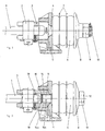
Die in der Fig. 1 dargestellte Zugeinrichtung gemäss dem Stand der Technik weist
einen Zugarm 1 auf, an dessen nicht ersichtlichem vorderen Ende ein Zughaken angeordnet
ist. Der Zugarm 1 ist mittels eines gesicherten Bolzens 2 mit dem Gabelkopf
3 verbunden. Letzterer geht in die einstückig mit ihm geformte eigentliche Zugstange
4 über. Sowohl der Gabelkopf 3 wie auch die Zugstange 4 werden in einer
Abstützung 5 geführt. Koaxial um die Zugstange 4 herum sind die aus elastomerem
Kunststoff bestehenden Federelemente 6 angeordnet, welche unter sich durch Zwischenscheiben
7 getrennt sind. Die Federelemente 6 stützen sich in Zugrichtung ab
auf die Abstützung 5, in Gegenrichtung, also fahrzeugseitig, auf eine Druckplatte 8.
Die Druckplatte 8 ist am fahrzeugseitigen Ende der Zugstange 4 mittels einer Kronenmutter
9 gesichert, welch letztere ihrerseits durch einen Splint 10 gesichert ist.
Die Abstützung 5 liegt in Zugrichtung an auf seitlich angeordneten Zuganschlägen
(nicht dargestellt); in Gegenrichtung wird sie normalerweise nicht belastet. Gehalten
wird die Abstützung mittels 4 Schrauben, welche die Grundplatte der Abstützung mit
den Längsträgem des Fahrzeuges verbinden jedoch nicht näher dargestellt sind.The traction device shown in FIG. 1 according to the prior art
a pull arm 1, at the front end, not shown, a pull hook is arranged
is. The pull arm 1 is by means of a secured
In der Fig. 2 wird eine beispielhafte Ausführungsform der erfindungsgemässen Zugeinrichtung
dargestellt, wobei gleiche Teile gleiche Bezugszeichen tragen und im wesentlichen
nur auf die Unterschiede zu der Ausbildungsform gemäss Fig. 1 näher
eingegangen wird. Bei der erfindungsgemässen Ausführungsform wird die Zugstange
11 durch eine mit einem Kopf 13 versehene Schraube 12 gebildet, welche
endseitig mit einem Aussengewinde 14a versehen ist und bei 14 in den mit einem
Innengewinde 14b versehenen Gabelkopf 3 eingeschraubt ist. Als Gewinde 14a, 14b
haben sich gerollte Gewinde, beispielsweise in der Dimension M60x2, als besonders
vorteilhaft erwiesen. Der Schraubenkopf 13 dient gleichzeitig als Anschlag für die
Druckplatte 8. Die Montage erfolgt in analoger Weise wie bei der beschriebenen
Zugeinrichtung nach dem Stand der Technik indem die Federelemente 6 stark zusammengepresst
werden, während die Schraube 12 eingedreht wird. Die Gewindeverbindung
14 wird einerseits durch Anschläge am Druckteller 8, welche auf den
Kopf 13 der Schraube 11 wirken, und anderseits durch eine mechanische Sicherung
gesichert. Die mechanische Sicherung der eingeschraubten Zugstange 11 wird durch
einen zweiteiligen Sicherungsring 16 gebildet, der in einer Nut 17 der Zugstange 11
aufgenommen ist. Der Gabelkopf 3 seinerseits ist im Bereich des zugseitigen Endes
der Zugstange 11 mit einem die Zugstange 11 umgebenden hohlzylindrischen Abschnitt
18 versehen, dessen Innendurchmesser zumindest annähernd dem Aussendurchmesser
des Sicherungsrings 16 entspricht. Dadurch wird sichergestellt, dass
der Sicherungsring 16 nicht aus der Nut 17 herausspringen kann. An den genannten
hohlzylindrischen Abschnitt 18 schliesst sich ein Abschnitt 19 an, der einen grösseren
Innendurchmesser bzw. eine grössere Öffnungsweite als der hohlzylindrische
Abschnitt 18 aufweist. Um den Sicherungsring 16 in der Nut 17 fixieren zu können,
wird die Zugstange 11 mit ihrem zugseitigen Ende entgegen der Vorspannkraft der
Federelemente 6 soweit in den Abschnitt 19 hineingeschraubt, dass der Sicherungsring
16 über den Abschnitt 19 eingeführt und über den zwischen Zugstange 11 und
Abschnitt 19 verbleibenden Zwischenraum in die Nut 17 eingesetzt werden kann.
Danach wird die Zugstange 11 wieder soweit zurückgedreht, bis sich der Sicherungsring
16 am hinteren Ende des hohlzylindrischen Abschnitts 18 anlegt. Eine derartige
Sicherung hat den grossen Vorteil, das deren Vorhandensein, im Gegensatz beispielsweise
zu einem selbsthärtenden Bindemittel, visuell überprüft werden kann,
wobei damit keinesfalls ausgeschlossen werden soll, dass für bestimmte Anwendungsfälle
ein selbsthärtendes Bindemittel zur Sicherung der Zugstange 11 vorgesehen
werden kann:2 shows an exemplary embodiment of the traction device according to the invention
shown, the same parts bearing the same reference numerals and essentially
only in more detail on the differences to the training form according to FIG. 1
is received. In the embodiment according to the invention, the
Das gezeigte Ausführungsbeispiel einer Zugeinrichtung kann schnell, einfach und
kostengünstig gefertigt werden. Zudem können, im Gegensatz zu einer einteiligen
Zugstange, die Zugschraube 11 oder der Gabelkopf 3 ggf. einzeln ersetzt und/oder
aus unterschiedlichen Materialien gefertigt werden.The illustrated embodiment of a traction device can be quick, simple and
can be manufactured inexpensively. In addition, unlike a one-piece
Tension rod, the
Claims (7)
- Traction device for a railway vehicle, comprising a forked head (3) intended to be connected to a draw hook of the vehicle and belonging to a drawbar (11), a pressure plate (8) which is arranged in the region of the end on the vehicle side of the drawbar (11) and which, in turn, bears on a fixing (13) arranged at the end on the vehicle side of the drawbar (11), and spring elements (6) which are arranged coaxially around the drawbar (11) and which, on one side, bear on the pressure plate (8) and, on the other side, in the pulling direction, bear on a support (5), characterized in that forked head (3) and drawbar (11) are formed in two pieces, the drawbar (11) being formed as a headed bolt (12) provided at the end on the traction side with a thread (14a), whose thread (14a) is screwed into a thread (14b) made in the forked head (3).
- Traction device according to Claim 1, characterized in that the drawbar (11) is provided with a mechanical securing means (16) at the end on the traction side.
- Traction device according to Claim 2, characterized in that, at the end on the traction side, the drawbar (11) is provided with a groove (17) to accommodate the mechanical securing means (16), the mechanical securing means being formed as a spring ring or as a two-part securing ring (16), and, in the region of the end on the traction side of the drawbar (11), the forked head (3) being provided with a hollow cylindrical section (18) which surrounds the drawbar (11) and whose internal diameter corresponds at least approximately to the external diameter of the spring ring or securing ring (16).
- Traction device according to Claim 3, characterized in that the hollow cylindrical section (18) is adjoined by a section (19) with a greater opening width or a greater diameter, and in that the drawbar (11) can be screwed with its end on the traction side into the aforementioned section (19), counter to the prestressing force of the spring elements (6), to such an extent that the mechanical securing means (16) can be fixed over the remaining interspace in the groove (17).
- Traction device according to Claim 1, characterized in that the screw connection (14) between forked head (3) and drawbar (11) is secured by means of a self-curing binder.
- Traction device according to one of the preceding claims, characterized in that, at the end on the traction side, the drawbar (11) is provided with a rolled thread (14a).
- Traction device according to one of Claims 1 to 3, characterized in that the screw connection (14) is secured by means of a mechanical antirotation safeguard on the pressure plate.
Applications Claiming Priority (2)
| Application Number | Priority Date | Filing Date | Title |
|---|---|---|---|
| CH129499 | 1999-07-14 | ||
| CH129499 | 1999-07-14 |
Publications (2)
| Publication Number | Publication Date |
|---|---|
| EP1069020A1 EP1069020A1 (en) | 2001-01-17 |
| EP1069020B1 true EP1069020B1 (en) | 2004-02-18 |
Family
ID=4207074
Family Applications (1)
| Application Number | Title | Priority Date | Filing Date |
|---|---|---|---|
| EP00810532A Expired - Lifetime EP1069020B1 (en) | 1999-07-14 | 2000-06-19 | Traction device for railway vehicles |
Country Status (3)
| Country | Link |
|---|---|
| EP (1) | EP1069020B1 (en) |
| AT (1) | ATE259732T1 (en) |
| DE (1) | DE50005302D1 (en) |
Cited By (1)
| Publication number | Priority date | Publication date | Assignee | Title |
|---|---|---|---|---|
| CN104494633A (en) * | 2014-12-10 | 2015-04-08 | 广州电力机车有限公司 | Locomotive traction device disassembling and assembling method |
Families Citing this family (2)
| Publication number | Priority date | Publication date | Assignee | Title |
|---|---|---|---|---|
| ATE449716T1 (en) | 2006-09-18 | 2009-12-15 | Schwab Verkehrstechnik Ag | TRAINING EQUIPMENT FOR RAIL VEHICLES |
| CN109178025B (en) * | 2018-09-03 | 2024-07-05 | 重庆中车长客轨道车辆有限公司 | Rail vehicle and coupler assembly and transition traction device thereof |
Family Cites Families (6)
| Publication number | Priority date | Publication date | Assignee | Title |
|---|---|---|---|---|
| USRE25110E (en) * | 1951-09-07 | 1962-01-09 | tucker | |
| US3166201A (en) * | 1963-06-10 | 1965-01-19 | Miner Inc W H | Railway car shock absorbing system |
| FR1385519A (en) * | 1963-12-02 | 1965-01-15 | Boirault App | Device with shock absorbers for mounting automatic single-traction couplers |
| DE1257190B (en) * | 1965-04-24 | 1967-12-28 | Krauss Maffei Ag | Device for supporting the buffer bar against the frame head carrier of rail vehicles |
| GB1207516A (en) * | 1967-12-18 | 1970-10-07 | Mini Verkehrswesen | Mounting fixture for an automatic central buffer coupling on rolling stock |
| DE2827641A1 (en) * | 1978-06-23 | 1980-01-10 | Unicupler Gmbh | Dampened coupling for railway carriage - has elastic cylinders spaced about coupling bar which is sliding fit through carriage chassis |
-
2000
- 2000-06-19 DE DE50005302T patent/DE50005302D1/en not_active Expired - Lifetime
- 2000-06-19 AT AT00810532T patent/ATE259732T1/en not_active IP Right Cessation
- 2000-06-19 EP EP00810532A patent/EP1069020B1/en not_active Expired - Lifetime
Cited By (1)
| Publication number | Priority date | Publication date | Assignee | Title |
|---|---|---|---|---|
| CN104494633A (en) * | 2014-12-10 | 2015-04-08 | 广州电力机车有限公司 | Locomotive traction device disassembling and assembling method |
Also Published As
| Publication number | Publication date |
|---|---|
| ATE259732T1 (en) | 2004-03-15 |
| EP1069020A1 (en) | 2001-01-17 |
| DE50005302D1 (en) | 2004-03-25 |
Similar Documents
| Publication | Publication Date | Title |
|---|---|---|
| DE3610976A1 (en) | PROFILE BOLT ASSEMBLY | |
| EP1996439B1 (en) | Jointed coupling for rail vehicles | |
| DE2246478C3 (en) | Junction connection of spatial framework constructions | |
| EP1069020B1 (en) | Traction device for railway vehicles | |
| EP1321317B1 (en) | Trailer hitch for motor vehicles | |
| DE69514215T2 (en) | Backlash-free drawbar arrangement for a freight wagon | |
| DE8617893U1 (en) | Compression spring tensioner | |
| DE29915697U1 (en) | Springy push and pull pin | |
| DE10309792B4 (en) | machine element | |
| EP1321316B1 (en) | Trailer hitch for motor vehicles | |
| DE4212180C2 (en) | Arrangement for fastening a chassis part | |
| DE3530565C2 (en) | Longitudinal force support of the coupling body of a trailer coupling | |
| DE3705740C2 (en) | ||
| EP3825202B1 (en) | Connecting rod, in particular for a central buffer coupling of a railway vehicle, and nut for connecting a connecting anchor of a connecting rod to a drawbar of the connecting rod | |
| DE3334250C2 (en) | ||
| EP4206056A1 (en) | Buffer, in particular for a rail vehicle | |
| DE2612426C2 (en) | Conical catch profiles for coupling bolts on agricultural implements | |
| DE1811573A1 (en) | Fuse for screw connection | |
| DE1780380B2 (en) | Storage for a tow bar of a trailer coupling carrying a coupling head | |
| DE102007055807A1 (en) | Steering cylinder attachment for use in steering vehicle axle of motor vehicle, has steering cylinder that is inserted with housing of steering vehicle axle by two plates that are connected with cylinder pipe | |
| DE8911375U1 (en) | Aircraft tow bar | |
| DE20120267U1 (en) | Trailer coupling, in particular for shunting vehicles | |
| DE8605706U1 (en) | Aircraft tow bar with a connector designed for attachment to the chassis of the nose wheel or nose wheels of an aircraft | |
| DE3712989A1 (en) | Tow rod | |
| DE10008297A1 (en) | Fastener for joining car components comprises bridging sleeve which fits over bolt and has tapering section which is compressed when bolt is tightened and fits against inner sleeve with indented outer surface |
Legal Events
| Date | Code | Title | Description |
|---|---|---|---|
| PUAI | Public reference made under article 153(3) epc to a published international application that has entered the european phase |
Free format text: ORIGINAL CODE: 0009012 |
|
| AK | Designated contracting states |
Kind code of ref document: A1 Designated state(s): AT BE CH CY DE DK ES FI FR GB GR IE IT LI LU MC NL PT SE |
|
| AX | Request for extension of the european patent |
Free format text: AL;LT;LV;MK;RO;SI |
|
| 17P | Request for examination filed |
Effective date: 20010322 |
|
| AKX | Designation fees paid |
Free format text: AT BE CH CY DE DK ES FI FR GB GR IE IT LI LU MC NL PT SE |
|
| GRAP | Despatch of communication of intention to grant a patent |
Free format text: ORIGINAL CODE: EPIDOSNIGR1 |
|
| GRAP | Despatch of communication of intention to grant a patent |
Free format text: ORIGINAL CODE: EPIDOSNIGR1 |
|
| GRAS | Grant fee paid |
Free format text: ORIGINAL CODE: EPIDOSNIGR3 |
|
| GRAA | (expected) grant |
Free format text: ORIGINAL CODE: 0009210 |
|
| AK | Designated contracting states |
Kind code of ref document: B1 Designated state(s): AT BE CH CY DE DK ES FI FR GB GR IE IT LI LU MC NL PT SE |
|
| PG25 | Lapsed in a contracting state [announced via postgrant information from national office to epo] |
Ref country code: IE Free format text: LAPSE BECAUSE OF FAILURE TO SUBMIT A TRANSLATION OF THE DESCRIPTION OR TO PAY THE FEE WITHIN THE PRESCRIBED TIME-LIMIT Effective date: 20040218 Ref country code: CY Free format text: LAPSE BECAUSE OF FAILURE TO SUBMIT A TRANSLATION OF THE DESCRIPTION OR TO PAY THE FEE WITHIN THE PRESCRIBED TIME-LIMIT Effective date: 20040218 Ref country code: FI Free format text: LAPSE BECAUSE OF FAILURE TO SUBMIT A TRANSLATION OF THE DESCRIPTION OR TO PAY THE FEE WITHIN THE PRESCRIBED TIME-LIMIT Effective date: 20040218 Ref country code: NL Free format text: LAPSE BECAUSE OF FAILURE TO SUBMIT A TRANSLATION OF THE DESCRIPTION OR TO PAY THE FEE WITHIN THE PRESCRIBED TIME-LIMIT Effective date: 20040218 |
|
| REG | Reference to a national code |
Ref country code: GB Ref legal event code: FG4D Free format text: NOT ENGLISH |
|
| REG | Reference to a national code |
Ref country code: CH Ref legal event code: EP Ref country code: CH Ref legal event code: NV Representative=s name: ROTTMANN, ZIMMERMANN + PARTNER AG |
|
| REG | Reference to a national code |
Ref country code: IE Ref legal event code: FG4D Free format text: GERMAN |
|
| REF | Corresponds to: |
Ref document number: 50005302 Country of ref document: DE Date of ref document: 20040325 Kind code of ref document: P |
|
| PG25 | Lapsed in a contracting state [announced via postgrant information from national office to epo] |
Ref country code: GR Free format text: LAPSE BECAUSE OF FAILURE TO SUBMIT A TRANSLATION OF THE DESCRIPTION OR TO PAY THE FEE WITHIN THE PRESCRIBED TIME-LIMIT Effective date: 20040518 Ref country code: DK Free format text: LAPSE BECAUSE OF FAILURE TO SUBMIT A TRANSLATION OF THE DESCRIPTION OR TO PAY THE FEE WITHIN THE PRESCRIBED TIME-LIMIT Effective date: 20040518 |
|
| PG25 | Lapsed in a contracting state [announced via postgrant information from national office to epo] |
Ref country code: ES Free format text: LAPSE BECAUSE OF FAILURE TO SUBMIT A TRANSLATION OF THE DESCRIPTION OR TO PAY THE FEE WITHIN THE PRESCRIBED TIME-LIMIT Effective date: 20040529 |
|
| REG | Reference to a national code |
Ref country code: SE Ref legal event code: TRGR |
|
| PG25 | Lapsed in a contracting state [announced via postgrant information from national office to epo] |
Ref country code: AT Free format text: LAPSE BECAUSE OF NON-PAYMENT OF DUE FEES Effective date: 20040619 Ref country code: LU Free format text: LAPSE BECAUSE OF NON-PAYMENT OF DUE FEES Effective date: 20040619 |
|
| GBT | Gb: translation of ep patent filed (gb section 77(6)(a)/1977) |
Effective date: 20040607 |
|
| PG25 | Lapsed in a contracting state [announced via postgrant information from national office to epo] |
Ref country code: MC Free format text: LAPSE BECAUSE OF NON-PAYMENT OF DUE FEES Effective date: 20040630 Ref country code: BE Free format text: LAPSE BECAUSE OF NON-PAYMENT OF DUE FEES Effective date: 20040630 |
|
| NLV1 | Nl: lapsed or annulled due to failure to fulfill the requirements of art. 29p and 29m of the patents act | ||
| REG | Reference to a national code |
Ref country code: IE Ref legal event code: FD4D |
|
| ET | Fr: translation filed | ||
| PLBE | No opposition filed within time limit |
Free format text: ORIGINAL CODE: 0009261 |
|
| STAA | Information on the status of an ep patent application or granted ep patent |
Free format text: STATUS: NO OPPOSITION FILED WITHIN TIME LIMIT |
|
| BERE | Be: lapsed |
Owner name: *SCHWAB VERKEHRSTECHNIK A.G. Effective date: 20040630 |
|
| 26N | No opposition filed |
Effective date: 20041119 |
|
| PG25 | Lapsed in a contracting state [announced via postgrant information from national office to epo] |
Ref country code: PT Free format text: LAPSE BECAUSE OF NON-PAYMENT OF DUE FEES Effective date: 20040718 |
|
| PGFP | Annual fee paid to national office [announced via postgrant information from national office to epo] |
Ref country code: SE Payment date: 20080519 Year of fee payment: 9 |
|
| REG | Reference to a national code |
Ref country code: CH Ref legal event code: NV Representative=s name: LUCHS & PARTNER PATENTANWAELTE |
|
| PG25 | Lapsed in a contracting state [announced via postgrant information from national office to epo] |
Ref country code: SE Free format text: LAPSE BECAUSE OF NON-PAYMENT OF DUE FEES Effective date: 20090620 |
|
| REG | Reference to a national code |
Ref country code: FR Ref legal event code: PLFP Year of fee payment: 17 |
|
| PGFP | Annual fee paid to national office [announced via postgrant information from national office to epo] |
Ref country code: GB Payment date: 20160621 Year of fee payment: 17 Ref country code: DE Payment date: 20160621 Year of fee payment: 17 |
|
| PGFP | Annual fee paid to national office [announced via postgrant information from national office to epo] |
Ref country code: FR Payment date: 20160627 Year of fee payment: 17 |
|
| PGFP | Annual fee paid to national office [announced via postgrant information from national office to epo] |
Ref country code: CH Payment date: 20160629 Year of fee payment: 17 Ref country code: IT Payment date: 20160628 Year of fee payment: 17 |
|
| REG | Reference to a national code |
Ref country code: DE Ref legal event code: R119 Ref document number: 50005302 Country of ref document: DE |
|
| REG | Reference to a national code |
Ref country code: CH Ref legal event code: PL |
|
| GBPC | Gb: european patent ceased through non-payment of renewal fee |
Effective date: 20170619 |
|
| REG | Reference to a national code |
Ref country code: FR Ref legal event code: ST Effective date: 20180228 |
|
| PG25 | Lapsed in a contracting state [announced via postgrant information from national office to epo] |
Ref country code: DE Free format text: LAPSE BECAUSE OF NON-PAYMENT OF DUE FEES Effective date: 20180103 Ref country code: GB Free format text: LAPSE BECAUSE OF NON-PAYMENT OF DUE FEES Effective date: 20170619 Ref country code: CH Free format text: LAPSE BECAUSE OF NON-PAYMENT OF DUE FEES Effective date: 20170630 Ref country code: LI Free format text: LAPSE BECAUSE OF NON-PAYMENT OF DUE FEES Effective date: 20170630 |
|
| PG25 | Lapsed in a contracting state [announced via postgrant information from national office to epo] |
Ref country code: IT Free format text: LAPSE BECAUSE OF NON-PAYMENT OF DUE FEES Effective date: 20170619 Ref country code: FR Free format text: LAPSE BECAUSE OF NON-PAYMENT OF DUE FEES Effective date: 20170630 |