EP1313658B1 - Dispositif de couplage de deux moyens de stockage et/ou d'acheminement avec un dispositif de nettoyage - Google Patents
Dispositif de couplage de deux moyens de stockage et/ou d'acheminement avec un dispositif de nettoyage Download PDFInfo
- Publication number
- EP1313658B1 EP1313658B1 EP01915087A EP01915087A EP1313658B1 EP 1313658 B1 EP1313658 B1 EP 1313658B1 EP 01915087 A EP01915087 A EP 01915087A EP 01915087 A EP01915087 A EP 01915087A EP 1313658 B1 EP1313658 B1 EP 1313658B1
- Authority
- EP
- European Patent Office
- Prior art keywords
- closure
- spigot
- cleaning
- closure flap
- shaft
- Prior art date
- Legal status (The legal status is an assumption and is not a legal conclusion. Google has not performed a legal analysis and makes no representation as to the accuracy of the status listed.)
- Expired - Lifetime
Links
Images

Classifications
-
- B—PERFORMING OPERATIONS; TRANSPORTING
- B65—CONVEYING; PACKING; STORING; HANDLING THIN OR FILAMENTARY MATERIAL
- B65G—TRANSPORT OR STORAGE DEVICES, e.g. CONVEYORS FOR LOADING OR TIPPING, SHOP CONVEYOR SYSTEMS OR PNEUMATIC TUBE CONVEYORS
- B65G69/00—Auxiliary measures taken, or devices used, in connection with loading or unloading
- B65G69/18—Preventing escape of dust
- B65G69/181—Preventing escape of dust by means of sealed systems
- B65G69/183—Preventing escape of dust by means of sealed systems with co-operating closure members on each of the parts of a separable transfer channel
-
- Y—GENERAL TAGGING OF NEW TECHNOLOGICAL DEVELOPMENTS; GENERAL TAGGING OF CROSS-SECTIONAL TECHNOLOGIES SPANNING OVER SEVERAL SECTIONS OF THE IPC; TECHNICAL SUBJECTS COVERED BY FORMER USPC CROSS-REFERENCE ART COLLECTIONS [XRACs] AND DIGESTS
- Y10—TECHNICAL SUBJECTS COVERED BY FORMER USPC
- Y10T—TECHNICAL SUBJECTS COVERED BY FORMER US CLASSIFICATION
- Y10T137/00—Fluid handling
- Y10T137/4238—With cleaner, lubrication added to fluid or liquid sealing at valve interface
- Y10T137/4245—Cleaning or steam sterilizing
- Y10T137/4259—With separate material addition
-
- Y—GENERAL TAGGING OF NEW TECHNOLOGICAL DEVELOPMENTS; GENERAL TAGGING OF CROSS-SECTIONAL TECHNOLOGIES SPANNING OVER SEVERAL SECTIONS OF THE IPC; TECHNICAL SUBJECTS COVERED BY FORMER USPC CROSS-REFERENCE ART COLLECTIONS [XRACs] AND DIGESTS
- Y10—TECHNICAL SUBJECTS COVERED BY FORMER USPC
- Y10T—TECHNICAL SUBJECTS COVERED BY FORMER US CLASSIFICATION
- Y10T137/00—Fluid handling
- Y10T137/8593—Systems
- Y10T137/87917—Flow path with serial valves and/or closures
- Y10T137/87925—Separable flow path section, valve or closure in each
- Y10T137/87933—Common joint and valve seat faces, or sections joined by closing members
-
- Y—GENERAL TAGGING OF NEW TECHNOLOGICAL DEVELOPMENTS; GENERAL TAGGING OF CROSS-SECTIONAL TECHNOLOGIES SPANNING OVER SEVERAL SECTIONS OF THE IPC; TECHNICAL SUBJECTS COVERED BY FORMER USPC CROSS-REFERENCE ART COLLECTIONS [XRACs] AND DIGESTS
- Y10—TECHNICAL SUBJECTS COVERED BY FORMER USPC
- Y10T—TECHNICAL SUBJECTS COVERED BY FORMER US CLASSIFICATION
- Y10T137/00—Fluid handling
- Y10T137/8593—Systems
- Y10T137/87917—Flow path with serial valves and/or closures
- Y10T137/87925—Separable flow path section, valve or closure in each
- Y10T137/87973—Coupling interlocked with valve, or closure or actuator
Definitions
- the invention relates to a device for coupling two storage and / or conveying means, such as in the form of containers, containers, pipes and / or the like Transfer of a product from a first storage and / or funding with one first closing flap in a first pipe socket at a first end and in operative connection with at least one shaft in a second storage and / or funding a second closing flap in a second pipe socket at a second end and in Operative connection with the at least one shaft, the closing flaps from a closed position, in which the first closing flap on the first storage and / or funding the first end is sealed from the atmosphere, the second closing flap closes the second Storage and / or conveyance means at the second end sealed against atmosphere locks and the two closing flaps and / or the two pipe sockets relative to each other are movable in a cleaning position in which the two closing flaps and / or two pipe sockets from each other, limiting one with a cleaning device connectable cleaning space are spaced, and by actuating the at least one Shaft in an open position in
- Such a device is known, for example, from DE 195 20 409 C1, in which the Cleaning device comprises a blowing and suction device, which cleaning the Closing flaps before and / or after a product transfer to be accomplished by means of the device or filling process with a gas.
- the Cleaning device comprises a blowing and suction device, which cleaning the Closing flaps before and / or after a product transfer to be accomplished by means of the device or filling process with a gas.
- a seal for use with a spacing of the closing flaps of preferably less than 15 mm the space between the shutters, i.e. the shock chamber disadvantageously with the exception of the areas of the bearing shells, seals to the outside. Consequently in the known device there is a risk of contamination of both the material to be transferred Product as well as the atmosphere. Also cleaning the shock chamber with a liquid is impossible due to leakage.
- a device for coupling two containers in which the pipe socket are rotatable relative to each other, so that by rotating the pipe socket a bayonet lock locks or unlocks relative to each other and at the same time the locking flaps from the closed position to the open position or from the open position to the Closing position are forced so that the locking position with the open position coincides.
- a lock is particularly disadvantageous in that during of the change from the closed position to the open position, or vice verca, also because of the use of only one bayonet lock, the closing flaps inadvertently from each other to be able to solve.
- cleaning before and / or after a transfer is in the open position is not in a locked state in order to avoid contamination, the atmosphere and / or the product to be decanted.
- the object of the present invention is therefore the generic device of this type to further develop the disadvantages of the prior art, in particular cleaning of the cleaning room, also in the area of the storage of the closing flaps, without contamination of the atmosphere and / or a product to be decanted.
- a secure closure of the closing flaps and / or pipe socket against each other before opening the flow opening (s) for a decanting process and after closing the Flow opening (s), especially in the cleaning position, must be guaranteed.
- this object is achieved by a first essentially ring-shaped one Seal between the first closing flap and the first pipe socket, a second essentially annular seal between the second closing flap and the second pipe socket, a third substantially annular seal between the first pipe socket and the second pipe socket and a fourth substantially annular seal between the second pipe socket and one cooperating with the at least one shaft and fixedly connected to the second closing flap, the second shaft section, the first, second, third and fourth seals the cleaning room both to the atmosphere and also seal to the product.
- first shaft section is a first semi-axis
- second shaft section is a solid axis, which with the second closing flap via a second Semi-axis is connected, and the first semi-axis and the second semi-axis become one Complete solid axis.
- preferred embodiments according to the invention are characterized by an actuating device, via the one safety device for changing from the closed position in a locking position in which the two storage and / or funding sealed against each other and the two closing flaps and / or the two pipe sockets are firmly connected to each other, then a swivel device for changing from the locking position in the open position and the open position in the locking position and then the safety device for changing from the locking position in the The closed position can be driven.
- the actuating device with a gear device a drive shaft and at least two output shafts, the two output shafts are alternately accessible from the drive shaft.
- the securing device on the one hand with the first output shaft and on the other hand with the two pipe sockets is in operative connection
- the securing device preferably being a connecting element comprises between the first pipe socket and the second pipe socket, which for locking of the two pipe sockets relative to one another or unlocking them, in particular via at least a bayonet lock, is rotatable about a first axis.
- the pivoting device on the one hand with the the at least one shaft forming second output shaft and on the other hand with at least one of the two closing flaps for rotating the closing flaps about a second axis in Operational connection is made, the pivoting device preferably the two semi-axes includes.
- the cleaning position between the closed position and the locking position as well as between the open position and the locking position with at least partially firmly connected closing flaps and / or pipe socket can be approached.
- the invention also proposes that the connecting member have at least one projection or has at least one recess, and each projection or recess of the connecting member with a recess or a projection of the first pipe socket and / or the second pipe socket is firmly engaged in the locking position, preferably each projection or recess of the connecting member or of the pipe socket (s) encloses an angle to the first axis at least in some areas or enclose the flaps by rotating the connector about the first Axis away from each other, especially between the open position and the locked position or towards each other, especially between the closed position and the locked position to move.
- the first closing flap has a first end face with at least one depression and / or elevation
- the second closing flap has a second end face complementary to the first end face
- the two End faces lie closely against one another at least in the open position, preferably in the cleaning position, the end faces in the area of the at least one depression and / or Raised are sealed against each other and the cleaning room is essentially ring-shaped is.
- first closing flap at least one first recess on its side opposite the first end face and / or the second closing flap has at least one second recess on its second one End face opposite side to enlarge the flow opening or flow openings has or have in the open position, preferably the first Recess and / or the second recess is substantially spherical segment-shaped or are.
- first closing flap at least in the open position partially engaged with the second pipe socket and / or the second closing flap is or are at least partially in engagement with the first pipe socket.
- first closing flap and / or the second closing flap at least one partially annular projection, preferably two opposing partially annular ones Projections, concentric to the second axis for engagement in at least one partially annular Recess in the first pipe socket and / or in the second pipe socket has or have.
- first closing flap and / or the second Closing flap at least one partially annular groove, preferably two opposite one another partially annular grooves, concentric to the second axis for engagement in at least one partially annular Recess in the first pipe socket and / or in the second pipe socket has or have.
- the second axis is substantially perpendicular to the first Axis stands.
- the first closing flap is a component of a passive valve and the second closing flap is part of an active valve, wherein preferably the second semiaxis is fixedly connected to the second output shaft.
- the cleaning device be a blowing and Suction device for flooding the cleaning room with a fluid detergent comprises.
- first, second, third and / or fourth seal (s) are resistant to Acids and / or bases is or are.
- the cleaning room acts as a lock.
- the cleaning room to a pressure below the atmospheric pressure and / or the pressure in the area of the flow opening is.
- the invention is characterized by a sensing unit for determining the Product concentration in the cleaning room, especially in operative connection with the actuating device.
- the invention is characterized in that when the value falls below a selectable Limit of the specific product concentration the actuator for driving the closing flap can be released into the closed position.
- the invention is therefore based on the surprising finding that in a cleaning position, both before and after a transfer, an area between the pipe sockets and at least part of the end faces of the closing flaps, the so-called shock chamber, the first time as an all-round closed cleaning room, which both to the outside atmosphere as well as sealed to the product room, executed and possibly before an unintended Break open due to at least partial locking of the pipe socket is protected against each other without the risk of contamination, be it the one to be filled Product and / or the atmosphere can be cleaned, even with a cleaning liquid.
- a safety device and a swivel device can be addressed, so that after coupling two containers, for example, by rotating a drive shaft
- the pipe sockets are firmly locked together at 90 ° using the swivel device are in the meantime producing the cleaning room, so that in the cleaning position impossible to separate the pipe socket and cleaning the cleaning room is possible while the shutters in the pipe socket for a tight seal the pipe socket and then by rotating the drive shaft from 90 ° to 180 ° the closing flaps are rotated into their open position via the swivel device to enable a refilling process.
- the flaps are returned to their closed position at 90 ° and from 90 ° to 0 ° the cleaning room is opened in the meantime, cleaned, and then the Disconnected pipe socket from each other.
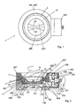
- a device 1 comprises a first one Pipe socket 10 on a first container, not shown, which, as soon as the first container with a second container, not shown, is coupled, with the interposition of a connecting element or connecting ring 2 in a second, two-part pipe socket 100, 100 'of the second container is stored.
- the two pipe sockets 10, 100, 100 ' again two valves 20, 120 are mounted, the first valve 20 being passive and the second Valve 120 can be active, so that only the active valve 120 for opening or closing of flow openings 200, 200 'from the first container to the second container is actively operable using a transmission device 300.
- connection ring 2 with two mutually opposite and extending along the inner circumference 3 provided, in each of which a projection 11 of the first pipe socket 10 engage each protrusion 11 extends along the outer circumference of the first pipe socket 10 extends at least partially in a curved shape, as shown in Figure 4.
- the first pipe socket 10 also has two mutually opposite recesses 12, in which engages the passive valve 20 in the locking position according to FIG. 2.
- the passive Valve 20 in turn comprises a flap 21 with an end face 22 in which a recess 23 is formed, and a spherical segment-shaped recess 24 on the end face 22 opposite side.
- the passive valve 20 is opposite the first pipe socket 10 sealed by means of a flap seal 25 and firmly connected to a semi-axis 26.
- the passive valve 20 also comprises two projections 27 for engaging in the recesses 12.
- the active valve 120 is in the second pipe socket 100 by engaging in two opposite recesses 102 are mounted.
- the active valve 120 in turn includes a flap 121 with an end face 122, from which a projection 127 stands out, and a spherical segment-shaped recess 124 on the opposite face 122 Page.
- the active valve 120 is also below the second pipe socket 100 Use of a flap seal 125 sealed.
- the flap 121 of the active valve 120 is firmly formed with a second semi-axis 126. Projections 127 also become engaged into the recesses 102 according to FIG. 2 provided by the active valve 120. Moreover is between the two flaps 21, 121 in the region of the recess 23 into which the elevation 128 partially engages, a further flap seal 129 is provided.
- Active valve 120 ' is shown in FIG. 3.
- Active valve 120 ' includes a flap 121 'with a flat end face 122' and a spherical segment Recess 124 'on its side opposite end face 122'.
- the Flap 121 ' provided on one side with a semiaxis 126', concentric to its longitudinal axis two semicircular projections 127 extend.
- the transmission device 300 comprises a drive shaft 301 with a disk 302 and a stopper 303, which alternately on a disc 304 with a recess 305 for driving a first output shaft 306 or on a disc 314 with a recess 315 for driving a second output shaft 316.
- the first output wave 306 is also connected to a washer 307 which is connected to the connecting ring 2 for rotating the same attacks while the second output shaft 316 in the first semi-axis 126 to actuate of the active valve 120 passes.
- Cleaning space 400 is provided between the pipe socket 10, 100 and the flaps 21, 121.
- a first is to seal the cleaning space 400 from the atmosphere Ring seal 401 between the two pipe sockets 10, 100 and a second ring seal 402 arranged between the second pipe socket 100 and the second output shaft 316.
- the flap seals provide a seal against the product space 25 and 125 ensured.
- the cleaning room 400 is also connectable to a cleaning device, not shown, which in turn includes a blowing and suction device.
- a further rotation of the drive shaft 301 causes the plug 303 to come out of the recess 305 releases and hooks into the recess 315 of the disc 314, so that then one transmit further rotational movement in the direction of arrow A to the second output shaft 316 becomes.
- the Valves 20, 120 in the open position shown in Figure 1 with the projections at the same time 27 on the first flap 21 in the recesses 102 of the second pipe socket 100 and the projections 127 on the second flap 121 into the recesses 12 of the first pipe socket 10 engage, which results in a locking of the valves 20, 120 with the pipe socket 10, 100, 100 ', which makes it impossible for the valves 20, 120 to be in the open position from one another to separate.
- a not shown can through the flow openings 200, 200 ' Flow product from the first container into the second container.
- the drive shaft 301 can then be in its starting position, thus against the direction of rotation A in Figure 2, are turned back, here again by rotating the second output shaft 316, the closing flaps 21, 121 into their respective Pipe socket 10, 100 for sealing the containers against each other up to the locking position be rotated.
- the plug 303 then changes again from the recess 315 in the recess 305 to the connection ring 2 through the first output shaft 306 Figure 2 shown cleaning position to rotate, in which a renewed cleaning of the cleaning room 400 is possible.
- the starting position of the drive shaft 301 will finally lock by releasing the connection between the protrusions 11 and the recesses 3, so that the two containers are separated from each other can be separated.
Claims (21)
- Dispositif pour connecter deux moyens de stockage et / ou de transport, se présentant par exemple sous la forme de réservoirs, de conteneurs, de tubes et / ou similaire et utilisé pour transférer un produit d'un premier moyen de stockage et / ou de transport avec un premier clapet de fermeture, disposé dans un premier segment de tube (10), à une première extrémité et coopérant avec au moins un arbre, vers un second moyen de stockage et / ou de transport avec un second clapet de fermeture disposé dans un second segment de tube (100, 100') à une seconde extrémité et coopérant avec au moins un arbre, où les clapets de fermeture peuvent être déplacés d'une position de fermeture (dans laquelle le premier clapet de fermeture (21) isole, de manière étanche, contre l'atmosphère, le premier moyen de stockage et / ou de transport à la première extrémité, le second clapet de fermeture (121) isole, de manière étanche contre l'atmosphère, le second moyen de stockage et / ou de transport à la seconde extrémité et les deux clapets de fermeture et / ou les deux segments de tubes sont mobiles l'un par rapport à l'autre) vers une position de nettoyage (dans laquelle les deux clapets de fermeture et / ou les deux segments de tubes sont espacés d'une manière limitée l'un de l'autre par un espace de nettoyage (400) susceptible d'être connecté avec une installation de nettoyage) et ensuite, par l'actionnement d'au moins un arbre, vers une position d'ouverture, dans laquelle les clapets de fermeture reposent l'un sur l'autre et dans laquelle au moins une ouverture d'écoulement est ouverte pour le produit entre le premier moyen de stockage et / ou de transport et le second moyen de stockage et / ou de transport ; et également, les clapets de fermeture peuvent être déplacés par l'actionnement d'au moins un arbre, de la position d'ouverture vers la position de nettoyage et ensuite vers la position de fermeture, caractérisé par
une première garniture d'étanchéité (25) de forme sensiblement annulaire, disposée entre le premier clapet de fermeture (21) et le premier segment de tube (10),
une seconde garniture d'étanchéité (125) de forme sensiblement annulaire entre le second clapet de fermeture (121) et le second segment de tube (100),
une troisième garniture d'étanchéité (401) de forme sensiblement annulaire (10) entre le premier segment de tube (10) et le second segment de tube (100) et
une quatrième garniture d'étanchéité (402) de forme sensiblement annulaire entre le second segment de tube (100) et une seconde section d'arbre coopérant avec au moins un arbre (316) et connectée solidement avec le second clapet de fermeture (121), où les première, seconde, troisième et quatrième garnitures d'étanchéité (25, 125, 401, 402) isolent l'espace de nettoyage (400) aussi bien de l'atmosphère que du produit. - Dispositif selon la revendication 1, caractérisé en ce que
la première section d'arbre est un premier demi-axe (26), que la seconde section d'arbre est un axe complet (316) qui est solidaire du second clapet de fermeture (121) par l'intermédiaire d'un second demi-axe (126) et que le premier demi-axe (26) et le second demi-axe (126) forment un arbre complet. - Dispositif selon la revendication 1 ou la revendication 2, caractérisé par
une installation de commande (300, 301, 302, 303, 304, 305, 306, 307, 314, 315, 316) pour actionner une installation de verrouillage (2, 3,11) pour passer d'une position de fermeture à une position de verrouillage dans laquelle les deux moyens de stockage et / ou de transport sont mutuellement isolés de manière étanche et les deux clapets de fermeture (21, 121, 121') et / ou les deux segments de tubes (10, 100, 100') sont tenus solidement ensemble, ensuite une installation de pivotement (26, 126, 126') pour passer de la position de verrouillage vers la position d'ouverture, ainsi que de la position d'ouverture vers la position de verrouillage et enfin l'installation de verrouillage pour passer de la position de verrouillage vers la position de fermeture. - Dispositif selon la revendication 3, caractérisé en ce que
l'installation de commande comporte une installation d'actionnement (300, 301, 302, 303, 304, 305, 306, 307, 314, 315, 316) avec un arbre d'actionnement (301) et au moins deux arbres de sortie (306, 316) , où les deux arbres de sortie (306, 316') peuvent être actionnés à tour de rôle par l'arbre d'actionnement (301). - Dispositif selon la revendication 4, caractérisé en ce que
l'installation de verrouillage (2, 3, 11) coopère, d'une part, avec le premier arbre de sortie (306) et, d'autre part, avec les deux segments de tubes (10, 100, 100'), et en ce que l'installation de verrouillage (2, 3, 11) comporte, de préférence, un élément de liaison (2) entre le premier segment de tube (10) et le second segment de tube (100, 100'), qui peut être tourné autour d'un premier axe pour verrouiller les deux segments de tubes (10, 100, 100') l'un avec l'autre ou les déverrouiller, en particulier au moyen d'au moins un emboítement à baïonnette (3, 11). - Dispositif selon la revendication 4 ou la revendication 5, caractérisé en ce que
l'installation de pivotement (26, 126, 126') coopère, d'une part, avec un second arbre de sortie (316) formant au moins un arbre et, d'autre part, avec un des deux clapets de fermeture (21, 121, 121') pour faire pivoter les clapets de fermeture (21, 121, 121') autour d'un second axe, l'installation de pivotement comprenant, de préférence, les deux demi-axes (26, 126, 126'). - Dispositif selon l'une des revendications 3 à 6, caractérisé en ce que
la position de nettoyage, aussi bien entre la position de fermeture et la position de verrouillage qu'entre la position d'ouverture et la position de verrouillage peut être atteinte avec les clapets de fermeture (21, 121, 121') et / ou les segments de tubes (10, 100, 100') tenus fermement ensemble, au moins partiellement. - Dispositif selon l'une des revendications 5 à 7, caractérisé en ce que
l'élément de liaison (2) comporte au moins une saillie ou au moins un évidement (3), que chaque saillie ou chaque évidement (3) de l'élément de liaison (2) est fermement engagé avec un évidement ou une saillie (11) du premier segment de tube (10) et / ou du second segment de tube dans la position de verrouillage et que, de préférence, chaque saillie (11) ou chaque évidement de l'élément de liaison (2) du segment de tube ou des segments de tubes (10) forme un angle avec le premier axe, ce qui permet d'éloigner les clapets de fermeture (21, 121, 121') l'un de l'autre par la rotation de l'élément de liaison (2) autour du premier axe, en particulier entre la position d'ouverture et la position de verrouillage ou de les rapprocher mutuellement, en particulier, entre la position de fermeture et la position de verrouillage. - Dispositif selon l'une des revendications précédentes, caractérisé en ce que
le premier clapet de fermeture (21) présente une première surface frontale (22) avec au moins une creusure (23) et / ou avec au moins une élévation, que le second clapet de fermeture (121) présente une seconde surface frontale (22) complémentaire de la première surface frontale (122), que les deux surfaces frontales (22, 122) se placent l'une au-dessus de l'autre et de manière étanche au moins dans la position d'ouverture, que, de préférence, dans la position de nettoyage, les surfaces frontales (22, 122') dans la région de la creusure ou des creusures (23) et / ou de l'élévation ou des élévations soient mutuellement étanches et que l'espace de nettoyage (400) soit sensiblement annulaire. - Dispositif selon l'une des revendications précédentes, caractérisé en ce que
le premier clapet de fermeture (21) comporte au moins un évidement (24) sur son côté opposé à la première surface frontale (22) et / ou le second clapet de fermeture (121, 121') comporte au moins un second évidement (124, 124') sur son côté opposé à la seconde surface frontale (122, 122'), pour augmenter l'ouverture d'écoulement ou les ouvertures d'écoulement (200, 200') dans la position d'ouverture et en ce que, de préférence, le premier évidement (24) ou / et le second évidement (124, 124') a / ont sensiblement la forme d'une portion de sphère. - Dispositif selon l'une des revendications précédentes, caractérisé en ce que
dans la position d'ouverture, le premier clapet de fermeture (21) vient s'engager, au moins partiellement, avec le second segment de tube (100) et / ou que le second clapet de fermeture (121,121') vient s'engager, au moins partiellement, avec le premier segment de tube (10). - Dispositif selon la revendication 11, caractérisé en ce que
le premier clapet de fermeture (21) ou / et le second clapet de fermeture (121,121') comprend ou comprennent au moins une saillie (27, 127, 127') ayant la forme d'un anneau partiel et, de préférence deux saillies opposées ayant chacune la forme d'un anneau partiel, concentrique ou concentriques avec le second axe pour venir s'engager avec au moins un évidement (12, 102) ayant la forme d'un anneau partiel dans le premier segment de tube (10) et / ou le second segment de tube (100). - Dispositif selon la revendication 11, caractérisé en ce que
le premier clapet de fermeture ou / et le second clapet de fermeture comprend ou comprennent au moins une rainure de forme partiellement annulaire et, de préférence, deux rainures de forme partiellement annulaire opposées et concentriques, par rapport au second axe, pour venir s'engager dans au moins un évidement de forme partiellement annulaire dans le premier segment de tube et / ou dans le second segment de tube. - Dispositif selon l'une des revendications 6 à 13, caractérisé en ce que
le second axe est sensiblement perpendiculaire au premier axe. - Dispositif selon l'une des revendications précédentes, caractérisé en ce que
le premier clapet de fermeture (21) fait partie d'une soupape passive (20), que le second clapet de fermeture (121, 121') fait partie d'une soupape active (120) et que, à ce moment et de préférence, le second demi-axe (126) est solidaire du second arbre de sortie (316). - Dispositif selon l'une des revendications précédentes, caractérisé en ce que
l'installation de nettoyage comporte une installation de soufflage et d'aspiration, pour purger l'espace de nettoyage (400) avec un milieu de nettoyage fluide. - Dispositif selon l'une des revendications précédentes, caractérisé en ce que
la première, la seconde, la troisième ou l et la quatrième garniture / garnitures d'étanchéité est / sont résistantes contre les acides et / ou les bases. - Dispositif selon l'une des revendications précédentes, caractérisé en ce que
l'espace de nettoyage (400) fonctionne comme écluse. - Dispositif selon l'une des revendications précédentes, caractérisé en ce que
l'espace de nettoyage (400) peut être amené à une pression inférieure à la pression atmosphérique et / ou inférieure à la pression dans la région de l'ouverture d'écoulement (200, 200'). - Dispositif selon l'une des revendications précédentes, caractérisé par
l'utilisation d'un capteur pour déterminer la concentration en produit dans l'espace de nettoyage (400), en particulier un capteur coopérant avec l'installation de commande (300, 301, 302, 303, 304, 305, 306, 307, 314, 315, 316). - Dispositif selon la revendication 20, caractérisé en ce que
lorsqu'une valeur limite choisie de la concentration du produit n'est plus atteinte, l'installation de commande (300, 301, 302, 303, 304, 305, 306, 307, 314, 315, 316) peut agir sur le clapet de fermeture (21, 121, 121') pour le mettre en position de fermeture.
Applications Claiming Priority (3)
| Application Number | Priority Date | Filing Date | Title |
|---|---|---|---|
| DE20014872U | 2000-08-28 | ||
| DE20014872U DE20014872U1 (de) | 2000-08-28 | 2000-08-28 | Vorrichtung zum Kuppeln zweier Aufbewahrungs- und/oder Fördermittel mit einer Reinigungseinrichtung |
| PCT/DE2001/000853 WO2002018247A1 (fr) | 2000-08-28 | 2001-03-06 | Dispositif de couplage de deux moyens de stockage et/ou d'acheminement avec un dispositif de nettoyage |
Publications (2)
| Publication Number | Publication Date |
|---|---|
| EP1313658A1 EP1313658A1 (fr) | 2003-05-28 |
| EP1313658B1 true EP1313658B1 (fr) | 2004-09-01 |
Family
ID=7945762
Family Applications (1)
| Application Number | Title | Priority Date | Filing Date |
|---|---|---|---|
| EP01915087A Expired - Lifetime EP1313658B1 (fr) | 2000-08-28 | 2001-03-06 | Dispositif de couplage de deux moyens de stockage et/ou d'acheminement avec un dispositif de nettoyage |
Country Status (6)
| Country | Link |
|---|---|
| US (1) | US6807979B2 (fr) |
| EP (1) | EP1313658B1 (fr) |
| JP (1) | JP4121850B2 (fr) |
| AT (1) | ATE275084T1 (fr) |
| DE (2) | DE20014872U1 (fr) |
| WO (1) | WO2002018247A1 (fr) |
Cited By (4)
| Publication number | Priority date | Publication date | Assignee | Title |
|---|---|---|---|---|
| EP1749770A2 (fr) | 2005-08-04 | 2007-02-07 | MBE Metall-Bearbeitung Etzgen GmbH | Dispositif de soupape pour relier des conteneurs |
| DE102008049129A1 (de) | 2008-09-26 | 2010-04-08 | Gea Niro Gmbh | Kupplungsverschluss sowie Befestigungsmodul und Andockeinrichtung, jeweils enthaltend diesen Kupplungsverschluss |
| US8539996B2 (en) | 2007-09-28 | 2013-09-24 | Gea Pharma Systems Ag | Docking device comprising two coupling closures for the environmentally sealed transfer of bulk material, having at least one locking unit |
| DE102021134272A1 (de) | 2021-12-22 | 2023-06-22 | Andocksysteme G.Untch GmbH | Vorrichtung und Verfahren zum kontaminationsfreien Verbinden eines ersten Leitungsendes mit einem zweiten Leitungsende |
Families Citing this family (13)
| Publication number | Priority date | Publication date | Assignee | Title |
|---|---|---|---|---|
| ITLU20000007A1 (it) * | 2000-11-30 | 2002-05-30 | Mech Design Di Ing Fabrizio Bellin I E Ing Edoar | Valvola con sistema di confinamento tramite connessione di semielementi che forma con essi un unico elemento funzionale, di facile montaggio e smontaggio. |
| ITBO20010261A1 (it) * | 2001-04-27 | 2002-10-27 | Zanchetta & C Srl | Unita' e metodo per lo scarico di materiale incoerente da un dispositivo erogatore |
| DE102004003511B4 (de) * | 2004-01-23 | 2007-04-26 | Gea Niro Gmbh | Wiederverschließbarer Andockverschluss sowie Andocksystem, Mehrfachkupplungsverschluss, Mehrfachandocksystem, Fördermittel und Behältnis, enthaltend diesen Andockverschluss, und Verfahren zum Befüllen, Umfüllen und/oder Entleeren von solchen Behältnissen und/oder Fördermitteln |
| DE102005021368A1 (de) * | 2005-05-04 | 2006-11-09 | Bayer Cropscience Ag | Verfahren und Vorrichtung zur emissionsarmen Entleerung von Inhaltsstoffen aus großen Weichverpackungen |
| GB0605531D0 (en) * | 2006-03-20 | 2006-04-26 | Powder Systems Ltd | Improvements Relating To Valves |
| WO2008071181A2 (fr) * | 2006-12-15 | 2008-06-19 | Gea Pharma Systems Ag | Obturateur de couplage et mécanisme d'accrochage contenant deux de ces obturateurs de couplage |
| TWM336219U (en) * | 2008-01-31 | 2008-07-11 | Gudeng Prec Industral Co Ltd | Gas filling apparatus and gas filling port thereof |
| FR2927062B1 (fr) * | 2008-02-04 | 2011-07-01 | Arkema France | Procede de remplissage securise de nanotubes de carbone, systeme de remplissage et installation industrielle mettant en oeuvre le procede. |
| DE102009025290A1 (de) * | 2009-06-15 | 2010-12-16 | Andocksysteme G. Untch Gmbh | Doppelklappenvorrichtung zum umweltdichten Verbinden zweier Behältnisse |
| EP2535630A1 (fr) | 2011-06-17 | 2012-12-19 | Eaton Hydraulics SAS | Raccord à demi-vannes papillon, à libération rapide |
| DE102013005226B4 (de) * | 2013-03-27 | 2017-11-16 | Krohne Messtechnik Gmbh | Messgerät |
| JP5415647B1 (ja) * | 2013-08-21 | 2014-02-12 | 株式会社ミウラ | スプリット弁 |
| US10961108B2 (en) | 2016-05-31 | 2021-03-30 | Agrotop Gmbh | Device for filling tanks with intermediate container |
Citations (2)
| Publication number | Priority date | Publication date | Assignee | Title |
|---|---|---|---|---|
| FR2640598A1 (fr) * | 1988-12-16 | 1990-06-22 | Constantin Pierre | Dispositif obturateur d'orifices de transfert de produit, notamment d'un conteneur a un autre |
| EP0619254B1 (fr) * | 1993-04-01 | 1995-05-17 | ELVECO msj S.A. | Installation et procédé de transfert de produits s'écoulant par gravité |
Family Cites Families (12)
| Publication number | Priority date | Publication date | Assignee | Title |
|---|---|---|---|---|
| GB888541A (en) | 1959-08-25 | 1962-01-31 | Kac Ltd | Improvements in self-sealing releasable couplings for use in fluid pressure lines |
| US5095946A (en) * | 1990-01-22 | 1992-03-17 | Victaulic Company Of America | Dry-break pipe coupling |
| US5295507A (en) * | 1992-01-29 | 1994-03-22 | Eli Lilly And Company | Containment valve that allows contamination free transfer |
| DE4342962C1 (de) * | 1993-12-16 | 1995-02-02 | Buck Chem Tech Werke | Vorrichtung zum Kuppeln von Behältnissen |
| FR2714709B1 (fr) * | 1994-01-05 | 1996-02-02 | Fmc Corp | Accouplement à ouverture d'urgence alimenté par une double vanne à boisseau sphérique à débordement nul. |
| DE19615646C2 (de) * | 1995-06-07 | 1997-06-26 | Glatt Systemtechnik Dresden | Kupplungseinrichtung zum Verbinden bzw. Verschließen der innerhalb zweier eigenständiger Gehäuse befindlichen Räume |
| DE19520409C1 (de) * | 1995-06-09 | 1996-10-02 | Buck Chem Tech Werke | Vorrichtung zum Kuppeln von Behältnissen mit Blas- und Absaugeinrichtung |
| EP0788989A3 (fr) * | 1995-09-20 | 1998-07-01 | Buck Werke GmbH & Co | Dispositif pour raccorder des récipients |
| IT1309681B1 (it) * | 1999-03-29 | 2002-01-30 | Zanchetta & C Srl | Impianto per lo scarico di materiale incoerente da un contenitore |
| ITPT990016A1 (it) * | 1999-08-27 | 2001-02-27 | Salvatore Lardieri | Sistema atto a consentire il permanere delle condizioni di sterilita'del prodotto contenuto all'interno di una struttura durante l'accoppia |
| DE29915973U1 (de) | 1999-09-10 | 2001-01-25 | Gei Gmbh | Vorrichtung zum Kuppeln zweier Behältnisse mit einer flexiblen Klappendichtung |
| US6311745B1 (en) * | 2000-06-05 | 2001-11-06 | Xerox Corporation | Systems and methods for dispensing powders |
-
2000
- 2000-08-28 DE DE20014872U patent/DE20014872U1/de not_active Expired - Lifetime
-
2001
- 2001-03-06 US US10/362,041 patent/US6807979B2/en not_active Expired - Fee Related
- 2001-03-06 AT AT01915087T patent/ATE275084T1/de not_active IP Right Cessation
- 2001-03-06 DE DE50103486T patent/DE50103486D1/de not_active Expired - Lifetime
- 2001-03-06 JP JP2002523377A patent/JP4121850B2/ja not_active Expired - Fee Related
- 2001-03-06 EP EP01915087A patent/EP1313658B1/fr not_active Expired - Lifetime
- 2001-03-06 WO PCT/DE2001/000853 patent/WO2002018247A1/fr active IP Right Grant
Patent Citations (2)
| Publication number | Priority date | Publication date | Assignee | Title |
|---|---|---|---|---|
| FR2640598A1 (fr) * | 1988-12-16 | 1990-06-22 | Constantin Pierre | Dispositif obturateur d'orifices de transfert de produit, notamment d'un conteneur a un autre |
| EP0619254B1 (fr) * | 1993-04-01 | 1995-05-17 | ELVECO msj S.A. | Installation et procédé de transfert de produits s'écoulant par gravité |
Cited By (6)
| Publication number | Priority date | Publication date | Assignee | Title |
|---|---|---|---|---|
| EP1749770A2 (fr) | 2005-08-04 | 2007-02-07 | MBE Metall-Bearbeitung Etzgen GmbH | Dispositif de soupape pour relier des conteneurs |
| US8539996B2 (en) | 2007-09-28 | 2013-09-24 | Gea Pharma Systems Ag | Docking device comprising two coupling closures for the environmentally sealed transfer of bulk material, having at least one locking unit |
| DE102008049129A1 (de) | 2008-09-26 | 2010-04-08 | Gea Niro Gmbh | Kupplungsverschluss sowie Befestigungsmodul und Andockeinrichtung, jeweils enthaltend diesen Kupplungsverschluss |
| EP2179949A2 (fr) | 2008-09-26 | 2010-04-28 | GEA Niro GmbH | Fermeture à accouplement ainsi que module de fixation et dispositif d'accrochage, chacun comportant ladite fermeture à accouplement |
| US8539995B2 (en) | 2008-09-26 | 2013-09-24 | Gea Pharma Systems Ag | Coupling lock and attachment module and docking device, each containing said coupling lock |
| DE102021134272A1 (de) | 2021-12-22 | 2023-06-22 | Andocksysteme G.Untch GmbH | Vorrichtung und Verfahren zum kontaminationsfreien Verbinden eines ersten Leitungsendes mit einem zweiten Leitungsende |
Also Published As
| Publication number | Publication date |
|---|---|
| WO2002018247A1 (fr) | 2002-03-07 |
| DE20014872U1 (de) | 2001-01-25 |
| EP1313658A1 (fr) | 2003-05-28 |
| US6807979B2 (en) | 2004-10-26 |
| US20040094211A1 (en) | 2004-05-20 |
| DE50103486D1 (de) | 2004-10-07 |
| ATE275084T1 (de) | 2004-09-15 |
| JP2004507415A (ja) | 2004-03-11 |
| JP4121850B2 (ja) | 2008-07-23 |
Similar Documents
| Publication | Publication Date | Title |
|---|---|---|
| EP1313658B1 (fr) | Dispositif de couplage de deux moyens de stockage et/ou d'acheminement avec un dispositif de nettoyage | |
| DE4342962C1 (de) | Vorrichtung zum Kuppeln von Behältnissen | |
| EP1315662B1 (fr) | Dispositif de couplage de deux moyens de stockage et/ou d'acheminement avec un dispositif de securite | |
| EP2761213B1 (fr) | Dispositif de vanne et procédé de transfert d'un milieu de transfert | |
| EP2179949B1 (fr) | Fermeture à accouplement ainsi que module de fixation et dispositif d'accrochage, chacun comportant ladite fermeture à accouplement | |
| EP2443054B1 (fr) | Dispositif à double clapet pour jonction, sans nuisance pour l'environnement, de deux récipients | |
| WO2008071181A2 (fr) | Obturateur de couplage et mécanisme d'accrochage contenant deux de ces obturateurs de couplage | |
| EP0910541B1 (fr) | Systeme d'etancheite pour clapet de fermeture d'un orifice de passage | |
| EP1213244A1 (fr) | Dispositif d'accouplement à deux plaques | |
| EP2193092B1 (fr) | Dispositif d'adossement comprenant deux fermetures de couplage pour le transfert, isolé de l'environnement, de matière en vrac, renfermant au moins une unité de verrouillage | |
| EP0669123A1 (fr) | Conteneur d'infusion avec deux embouts de raccordements | |
| DE3407039A1 (de) | Mit absperrventil kombiniertes druckluftkupplungsteil | |
| DE202009018738U1 (de) | Leicht lösbares Kupplungssystem zur axialen Kupplung von zwei Flanschen | |
| DE2707642A1 (de) | Verschlussdeckel fuer einen fuellstutzen | |
| DE102019108869A1 (de) | Mischer mit Verschlussdeckel | |
| DE102019131680B4 (de) | Andockverschluss und Verfahren zum kontaminationsfreien Verbinden eines ersten Hohlraums mit einem zweiten Hohlraum | |
| DE19534915C1 (de) | Vorrichtung zum Kuppeln von Behältnissen | |
| EP0091976B1 (fr) | Robinet à boisseau sphérique | |
| DE602005005011T2 (de) | Klappenventil mit Blockiereinrichtung | |
| DE3313257A1 (de) | Schnellverschlusskupplung | |
| DE2263397A1 (de) | Kupplung | |
| CH716193B1 (de) | Doppelklappenventil für eine Übergabevorrichtung. | |
| DE202007013675U1 (de) | Entnahme- und Transportwerkzeug | |
| DE10031450A1 (de) | Doppelsitz-Klappventil mit Leckagesicherung | |
| WO2024002580A1 (fr) | Dispositif d'accouplement |
Legal Events
| Date | Code | Title | Description |
|---|---|---|---|
| PUAI | Public reference made under article 153(3) epc to a published international application that has entered the european phase |
Free format text: ORIGINAL CODE: 0009012 |
|
| AK | Designated contracting states |
Designated state(s): AT BE CH CY DE DK ES FI FR GB GR IE IT LI LU MC NL PT SE TR |
|
| 17P | Request for examination filed |
Effective date: 20030123 |
|
| RIN1 | Information on inventor provided before grant (corrected) |
Inventor name: MOELLER, KLAUS Inventor name: KOCH, MARTIN Inventor name: ELSAESSER, BERND |
|
| TPAC | Observations filed by third parties |
Free format text: ORIGINAL CODE: EPIDOSNTIPA |
|
| GRAP | Despatch of communication of intention to grant a patent |
Free format text: ORIGINAL CODE: EPIDOSNIGR1 |
|
| GRAS | Grant fee paid |
Free format text: ORIGINAL CODE: EPIDOSNIGR3 |
|
| GRAA | (expected) grant |
Free format text: ORIGINAL CODE: 0009210 |
|
| AK | Designated contracting states |
Kind code of ref document: B1 Designated state(s): AT BE CH CY DE DK ES FI FR GB GR IE IT LI LU MC NL PT SE TR |
|
| PG25 | Lapsed in a contracting state [announced via postgrant information from national office to epo] |
Ref country code: FI Free format text: LAPSE BECAUSE OF FAILURE TO SUBMIT A TRANSLATION OF THE DESCRIPTION OR TO PAY THE FEE WITHIN THE PRESCRIBED TIME-LIMIT Effective date: 20040901 Ref country code: TR Free format text: LAPSE BECAUSE OF FAILURE TO SUBMIT A TRANSLATION OF THE DESCRIPTION OR TO PAY THE FEE WITHIN THE PRESCRIBED TIME-LIMIT Effective date: 20040901 Ref country code: NL Free format text: LAPSE BECAUSE OF FAILURE TO SUBMIT A TRANSLATION OF THE DESCRIPTION OR TO PAY THE FEE WITHIN THE PRESCRIBED TIME-LIMIT Effective date: 20040901 Ref country code: ES Free format text: LAPSE BECAUSE OF FAILURE TO SUBMIT A TRANSLATION OF THE DESCRIPTION OR TO PAY THE FEE WITHIN THE PRESCRIBED TIME-LIMIT Effective date: 20040901 |
|
| REG | Reference to a national code |
Ref country code: GB Ref legal event code: FG4D Free format text: NOT ENGLISH |
|
| REG | Reference to a national code |
Ref country code: CH Ref legal event code: EP |
|
| GBT | Gb: translation of ep patent filed (gb section 77(6)(a)/1977) |
Effective date: 20040901 |
|
| REG | Reference to a national code |
Ref country code: IE Ref legal event code: FG4D Free format text: GERMAN |
|
| REF | Corresponds to: |
Ref document number: 50103486 Country of ref document: DE Date of ref document: 20041007 Kind code of ref document: P |
|
| REG | Reference to a national code |
Ref country code: CH Ref legal event code: NV Representative=s name: NOVAGRAAF INTERNATIONAL SA |
|
| PG25 | Lapsed in a contracting state [announced via postgrant information from national office to epo] |
Ref country code: SE Free format text: LAPSE BECAUSE OF FAILURE TO SUBMIT A TRANSLATION OF THE DESCRIPTION OR TO PAY THE FEE WITHIN THE PRESCRIBED TIME-LIMIT Effective date: 20041201 Ref country code: GR Free format text: LAPSE BECAUSE OF FAILURE TO SUBMIT A TRANSLATION OF THE DESCRIPTION OR TO PAY THE FEE WITHIN THE PRESCRIBED TIME-LIMIT Effective date: 20041201 Ref country code: DK Free format text: LAPSE BECAUSE OF FAILURE TO SUBMIT A TRANSLATION OF THE DESCRIPTION OR TO PAY THE FEE WITHIN THE PRESCRIBED TIME-LIMIT Effective date: 20041201 |
|
| NLV1 | Nl: lapsed or annulled due to failure to fulfill the requirements of art. 29p and 29m of the patents act | ||
| PG25 | Lapsed in a contracting state [announced via postgrant information from national office to epo] |
Ref country code: CY Free format text: LAPSE BECAUSE OF FAILURE TO SUBMIT A TRANSLATION OF THE DESCRIPTION OR TO PAY THE FEE WITHIN THE PRESCRIBED TIME-LIMIT Effective date: 20050306 Ref country code: AT Free format text: LAPSE BECAUSE OF NON-PAYMENT OF DUE FEES Effective date: 20050306 Ref country code: LU Free format text: LAPSE BECAUSE OF NON-PAYMENT OF DUE FEES Effective date: 20050306 |
|
| ET | Fr: translation filed | ||
| PG25 | Lapsed in a contracting state [announced via postgrant information from national office to epo] |
Ref country code: MC Free format text: LAPSE BECAUSE OF NON-PAYMENT OF DUE FEES Effective date: 20050331 |
|
| PLBE | No opposition filed within time limit |
Free format text: ORIGINAL CODE: 0009261 |
|
| STAA | Information on the status of an ep patent application or granted ep patent |
Free format text: STATUS: NO OPPOSITION FILED WITHIN TIME LIMIT |
|
| 26N | No opposition filed |
Effective date: 20050602 |
|
| REG | Reference to a national code |
Ref country code: CH Ref legal event code: PFA Owner name: GEA NIRO GMBH Free format text: GEA BUCK VALVE GMBH#MAUCHENER STRASSE 14#79379 MUELLHEIM (DE) -TRANSFER TO- GEA NIRO GMBH#MAUCHENER STRASSE 14#79379 MUELLHEIM (DE) |
|
| REG | Reference to a national code |
Ref country code: FR Ref legal event code: CD |
|
| PG25 | Lapsed in a contracting state [announced via postgrant information from national office to epo] |
Ref country code: PT Free format text: LAPSE BECAUSE OF NON-PAYMENT OF DUE FEES Effective date: 20050201 |
|
| REG | Reference to a national code |
Ref country code: CH Ref legal event code: NV Representative=s name: E. BLUM & CO. AG PATENT- UND MARKENANWAELTE VSP Ref country code: CH Ref legal event code: PUE Owner name: GEA PHARMA SYSTEMS AG Free format text: GEA NIRO GMBH#MAUCHENER STRASSE 14#79379 MUELLHEIM (DE) -TRANSFER TO- GEA PHARMA SYSTEMS AG#HAUPTSTRASSE 145#4416 BUBENDORF (CH) |
|
| REG | Reference to a national code |
Ref country code: GB Ref legal event code: 732E Free format text: REGISTERED BETWEEN 20100819 AND 20100825 |
|
| BECA | Be: change of holder's address |
Owner name: GEA PHARMA SYSTEMS A.G.HAUPTSTRASSE 145, CH-4416 B Effective date: 20100917 |
|
| BECH | Be: change of holder |
Owner name: GEA PHARMA SYSTEMS A.G. Effective date: 20100917 |
|
| REG | Reference to a national code |
Ref country code: FR Ref legal event code: TP |
|
| PGFP | Annual fee paid to national office [announced via postgrant information from national office to epo] |
Ref country code: FR Payment date: 20120319 Year of fee payment: 12 Ref country code: IE Payment date: 20120312 Year of fee payment: 12 |
|
| PGFP | Annual fee paid to national office [announced via postgrant information from national office to epo] |
Ref country code: IT Payment date: 20120320 Year of fee payment: 12 Ref country code: BE Payment date: 20120328 Year of fee payment: 12 |
|
| BERE | Be: lapsed |
Owner name: GEA PHARMA SYSTEMS A.G. Effective date: 20130331 |
|
| REG | Reference to a national code |
Ref country code: FR Ref legal event code: ST Effective date: 20131129 |
|
| REG | Reference to a national code |
Ref country code: IE Ref legal event code: MM4A |
|
| PG25 | Lapsed in a contracting state [announced via postgrant information from national office to epo] |
Ref country code: IE Free format text: LAPSE BECAUSE OF NON-PAYMENT OF DUE FEES Effective date: 20130306 Ref country code: FR Free format text: LAPSE BECAUSE OF NON-PAYMENT OF DUE FEES Effective date: 20130402 Ref country code: BE Free format text: LAPSE BECAUSE OF NON-PAYMENT OF DUE FEES Effective date: 20130331 |
|
| PG25 | Lapsed in a contracting state [announced via postgrant information from national office to epo] |
Ref country code: IT Free format text: LAPSE BECAUSE OF NON-PAYMENT OF DUE FEES Effective date: 20130306 |
|
| PGFP | Annual fee paid to national office [announced via postgrant information from national office to epo] |
Ref country code: GB Payment date: 20200325 Year of fee payment: 20 |
|
| PGFP | Annual fee paid to national office [announced via postgrant information from national office to epo] |
Ref country code: CH Payment date: 20200326 Year of fee payment: 20 |
|
| PGFP | Annual fee paid to national office [announced via postgrant information from national office to epo] |
Ref country code: DE Payment date: 20200331 Year of fee payment: 20 |
|
| REG | Reference to a national code |
Ref country code: DE Ref legal event code: R071 Ref document number: 50103486 Country of ref document: DE |
|
| REG | Reference to a national code |
Ref country code: CH Ref legal event code: PL |
|
| REG | Reference to a national code |
Ref country code: GB Ref legal event code: PE20 Expiry date: 20210305 |
|
| PG25 | Lapsed in a contracting state [announced via postgrant information from national office to epo] |
Ref country code: GB Free format text: LAPSE BECAUSE OF EXPIRATION OF PROTECTION Effective date: 20210305 |