EP1311417B1 - Elektromagnetisch betätigtes ventil, insbesondere für hydraulische bremsanlagen in kraftfahrzeugen - Google Patents
Elektromagnetisch betätigtes ventil, insbesondere für hydraulische bremsanlagen in kraftfahrzeugen Download PDFInfo
- Publication number
- EP1311417B1 EP1311417B1 EP01960143A EP01960143A EP1311417B1 EP 1311417 B1 EP1311417 B1 EP 1311417B1 EP 01960143 A EP01960143 A EP 01960143A EP 01960143 A EP01960143 A EP 01960143A EP 1311417 B1 EP1311417 B1 EP 1311417B1
- Authority
- EP
- European Patent Office
- Prior art keywords
- valve
- seat
- magnet armature
- plunger
- armature
- Prior art date
- Legal status (The legal status is an assumption and is not a legal conclusion. Google has not performed a legal analysis and makes no representation as to the accuracy of the status listed.)
- Expired - Lifetime
Links
- 238000007789 sealing Methods 0.000 claims description 4
- 230000007704 transition Effects 0.000 claims description 3
- 238000000418 atomic force spectrum Methods 0.000 claims 1
- 230000000630 rising effect Effects 0.000 claims 1
- 238000013461 design Methods 0.000 abstract description 7
- 230000000694 effects Effects 0.000 abstract description 4
- 238000004804 winding Methods 0.000 description 7
- 238000010586 diagram Methods 0.000 description 4
- 238000010276 construction Methods 0.000 description 2
- 238000013459 approach Methods 0.000 description 1
- 230000000712 assembly Effects 0.000 description 1
- 238000000429 assembly Methods 0.000 description 1
- 238000004891 communication Methods 0.000 description 1
- 230000006835 compression Effects 0.000 description 1
- 238000007906 compression Methods 0.000 description 1
- 239000004020 conductor Substances 0.000 description 1
- 230000003247 decreasing effect Effects 0.000 description 1
- 230000001419 dependent effect Effects 0.000 description 1
- 230000008030 elimination Effects 0.000 description 1
- 238000003379 elimination reaction Methods 0.000 description 1
- 230000007849 functional defect Effects 0.000 description 1
- 238000004519 manufacturing process Methods 0.000 description 1
- 238000000034 method Methods 0.000 description 1
Images
Classifications
-
- B—PERFORMING OPERATIONS; TRANSPORTING
- B60—VEHICLES IN GENERAL
- B60T—VEHICLE BRAKE CONTROL SYSTEMS OR PARTS THEREOF; BRAKE CONTROL SYSTEMS OR PARTS THEREOF, IN GENERAL; ARRANGEMENT OF BRAKING ELEMENTS ON VEHICLES IN GENERAL; PORTABLE DEVICES FOR PREVENTING UNWANTED MOVEMENT OF VEHICLES; VEHICLE MODIFICATIONS TO FACILITATE COOLING OF BRAKES
- B60T8/00—Arrangements for adjusting wheel-braking force to meet varying vehicular or ground-surface conditions, e.g. limiting or varying distribution of braking force
- B60T8/32—Arrangements for adjusting wheel-braking force to meet varying vehicular or ground-surface conditions, e.g. limiting or varying distribution of braking force responsive to a speed condition, e.g. acceleration or deceleration
- B60T8/34—Arrangements for adjusting wheel-braking force to meet varying vehicular or ground-surface conditions, e.g. limiting or varying distribution of braking force responsive to a speed condition, e.g. acceleration or deceleration having a fluid pressure regulator responsive to a speed condition
- B60T8/36—Arrangements for adjusting wheel-braking force to meet varying vehicular or ground-surface conditions, e.g. limiting or varying distribution of braking force responsive to a speed condition, e.g. acceleration or deceleration having a fluid pressure regulator responsive to a speed condition including a pilot valve responding to an electromagnetic force
-
- B—PERFORMING OPERATIONS; TRANSPORTING
- B60—VEHICLES IN GENERAL
- B60T—VEHICLE BRAKE CONTROL SYSTEMS OR PARTS THEREOF; BRAKE CONTROL SYSTEMS OR PARTS THEREOF, IN GENERAL; ARRANGEMENT OF BRAKING ELEMENTS ON VEHICLES IN GENERAL; PORTABLE DEVICES FOR PREVENTING UNWANTED MOVEMENT OF VEHICLES; VEHICLE MODIFICATIONS TO FACILITATE COOLING OF BRAKES
- B60T8/00—Arrangements for adjusting wheel-braking force to meet varying vehicular or ground-surface conditions, e.g. limiting or varying distribution of braking force
- B60T8/32—Arrangements for adjusting wheel-braking force to meet varying vehicular or ground-surface conditions, e.g. limiting or varying distribution of braking force responsive to a speed condition, e.g. acceleration or deceleration
- B60T8/34—Arrangements for adjusting wheel-braking force to meet varying vehicular or ground-surface conditions, e.g. limiting or varying distribution of braking force responsive to a speed condition, e.g. acceleration or deceleration having a fluid pressure regulator responsive to a speed condition
- B60T8/36—Arrangements for adjusting wheel-braking force to meet varying vehicular or ground-surface conditions, e.g. limiting or varying distribution of braking force responsive to a speed condition, e.g. acceleration or deceleration having a fluid pressure regulator responsive to a speed condition including a pilot valve responding to an electromagnetic force
- B60T8/3615—Electromagnetic valves specially adapted for anti-lock brake and traction control systems
- B60T8/3655—Continuously controlled electromagnetic valves
- B60T8/366—Valve details
- B60T8/367—Seat valves, e.g. poppet valves
-
- B—PERFORMING OPERATIONS; TRANSPORTING
- B60—VEHICLES IN GENERAL
- B60T—VEHICLE BRAKE CONTROL SYSTEMS OR PARTS THEREOF; BRAKE CONTROL SYSTEMS OR PARTS THEREOF, IN GENERAL; ARRANGEMENT OF BRAKING ELEMENTS ON VEHICLES IN GENERAL; PORTABLE DEVICES FOR PREVENTING UNWANTED MOVEMENT OF VEHICLES; VEHICLE MODIFICATIONS TO FACILITATE COOLING OF BRAKES
- B60T15/00—Construction arrangement, or operation of valves incorporated in power brake systems and not covered by groups B60T11/00 or B60T13/00
- B60T15/02—Application and release valves
- B60T15/025—Electrically controlled valves
- B60T15/028—Electrically controlled valves in hydraulic systems
Definitions
- the invention is based on an electromagnetic actuated valve according to the preamble of claim 1.
- the known valve has the disadvantage that the Plunger anchor principle increased expenses in the constructive design of pole core and magnet armature requires.
- low radial tolerances between the armature and the pole core required to get small secondary air column.
- the known valve is therefore expensive to manufacture.
- the invention electromagnetically actuated valve with the features of claim 1 has compared to mentioned initially proportional valve has the advantage that it the simple construction of a two-position valve with a Flat anchor has, however, like a proportional valve behaves. Since the flat anchor the field lines of the magnetic circuit in the working air gap essentially between each other facing, flat faces of Polkern and magnet armature run, are in this design radial tolerances of little influence. Furthermore, the design of the Seat valve and ram area to a stable Control behavior of working as a pressure control valve, Valve according to the invention in: The on the side of the Pressure medium inlet prevailing pressure supports the Magnetic force to open the seat valve.
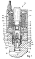
- FIG. 1 shows a Longitudinal section of an electromagnetically operated valve with a seat valve
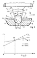
- Figure 2 the energized in the closed position located seat valve in comparison with Figure 1 enlarged Scale
- Figure 3 is a diagram of the valve over the Valve opening stroke acting forces.
- Electromagnetically operated valve 10 for hydraulic Braking systems of motor vehicles consists essentially from two assemblies: one in a stepped bore 11 of a Valve block 12 attached hydraulic part 13 and a on the hydraulic part plugged electrical part 14th
- the hydraulic part 13 of the valve 10 has a longitudinal pierced valve body 16, which with a Anchor guide sleeve 17 is connected.
- the valve body 16 and the anchor guide sleeve 17 are connected by a first Calking 18 in the stepped bore 11 of the Valve block 12 attached.
- the valve body 16 has a Pressure medium inlet 19 of the valve 10, which with a opening at the bottom of the bore of the stepped bore 11 Inflow channel 20 is in communication for pressure medium. Between the pressure medium inlet 19 and the inflow channel 20th is in the stepped bore 11, a filter disc 21st added.
- Valve body 16 In the area facing away from the bottom of the hole is the Valve body 16 is provided with an inflow bore 23, which merges into a hollow cone-shaped valve seat 24.
- Valve seat 24 is a formed on a plunger 25, hemispherical closing member 26 assigned.
- the valve seat 24 and the closing member 26 form a seat valve 27, the will be described in more detail below with reference to FIG 2.
- armature guide sleeve 17 closes on the Valve body 16 to a valve chamber 29, in a Magnet armature 30 is guided longitudinally movable.
- the magnet armature 30 has essentially the shape of a straight Circular cylinder with radially extending end faces 31 and 32. From the valve body 16 facing end face 31st goes on the plunger 25, which with a pin 33 in the Magnetic armature 20 is pressed.
- the between the valve body 16 and the armature 30 located part of the valve chamber 29th is through an opening 34 of the armature guide sleeve 17 with a pressure medium outlet 35 of the valve 10 and on with an opening into the stepped bore 11 outflow channel 36th the valve block 12 in conjunction.
- Apart from the pestle 25 is that between the valve body 16 and the armature 30th lying part of the valve chamber 29 free of internals.
- the armature 30 has a relatively large radial clearance to Anchor guide sleeve 17. He is using two over his entire Length extending longitudinal grooves 38 provided. By doing Magnetic armature 30 is in the region of its from the valve body 16th remote end face 32, a return spring 39 in the form recorded a helical compression spring. This one has relatively high rigidity and attacks with bias on one Residual air gap disk 40, which at a radial extending end face 41 of a pole core 42 supported is. The pole core 42 engages with part of its length in the armature guide sleeve 17, with which he pressure-tight connected is. Between the end face 32 of the magnet armature 30 and the residual air gap disk 40 is a the Opening stroke of the valve 10 determining working air gap 43.
- the shell side In the stepped bore 11 of the valve block 12 is the shell side the armature guide sleeve 17 a between the Pressure medium outlet 35 and the discharge channel 36 arranged Filter sleeve 45 added. This follows to the mouth of the Stepped bore 11 toward a sealing ring 46, a disc 47 and a socket 48, which by a second caulking 49 fixed in the stepped bore 11 of the valve block 12 is.
- the plugged onto the hydraulic part 13 of the valve electrical part 14 has one of a housing 50 with a Ring disc 51 enclosed coil 52 with an electric Winding 53. While the housing 50 radially inward on the Polkern 42 connects, provides the annular disc 51 a Connection to the socket 48 ago.
- the armature 30, the pole core 42, the socket 48, the Housing 50 and the annular disc 51 are made of magnetic conductive material, while the armature guide sleeve 17 and the residual air gap disc 40 are magnetically non-conductive.
- a generated when energized electrical winding 53 Magnetic circuit extends over the pole core 42, the Residual air gap disk 40, the armature 30, the Anchor guide sleeve 17, the annular disc 51 and the housing 50th of the electrical part 14.
- the armature 30 work and the pole core 42 according to the flat armature principle together.
- valve 10 as a pressure control valve important area of the seat valve 27 has the following constructive features, which described with reference to Figure 2 become:
- the hollow cone-shaped valve seat 24 has a cone angle ⁇ , which is at most 75 °.
- the valve seat 24 is limited against the valve chamber 29 by a flat recess 55 of the valve body 16 sharp-edged.
- the radius R 1 of the hemispherical closing member 26 is matched to the valve seat 24 such that the diameter D 1 of the inflow bore 23 almost corresponds to the sealing diameter D 2 of the poppet valve 27.
- On the closing member 26 is followed by a relatively short cylindrical portion 56 of the plunger 25th
- the cylindrical portion 56 has a twice the radius R 1 of the closing member 26 corresponding diameter D 3rd
- a conical portion 57 of the plunger 25 connects step-free against the armature 30. This has a cone angle ⁇ of about 35 ° and goes with rounded transition with the radius R 2 in the end face 31 of the magnet armature 30 steplessly over.
- a pressure p 1 which is provided in the case of the use of the valve 10 in the aforementioned foreign-power brake system of a high-pressure pump or a pressure medium accumulator.
- a pressure p 2 prevail between the value 0 and p 1 .
- the solenoid-operated valve 10 has the following Functionality:
- the profile of the spring force F F originating from the return spring 39 is indicated as a straight line which has a monotonously increasing profile with increasing valve opening stroke H.
- the second characteristic curve shows the profile of the additively linked magnetic force F M and hydraulic force F p at a constant current I and a constant pressure difference ⁇ p between the pressures p 1 and p 2 .
- the characteristic F M + M p has a monotonously increasing course with increasing valve opening stroke H, but the slope of which is less than that of the characteristic curve F F.
- This relatively flat course of the characteristic curve F M + Fp is achieved essentially by the design of the magnetic circuit by a relatively large working air gap 43 and a relatively thick residual air disc 40.
- the influence of the hydraulic force F p on plunger 25 and armature 30 is kept low in that the sealing diameter D 2 is relatively small and the magnet armature 30 is pressure-fluid-flushed on all sides.
- the characteristic F M + F p in the diagram is displaceable and, accordingly, the operating point AP can be set to a different stroke h.
- the spring force F F provided by the return spring 30 transfers the seat valve 27 into the closed position when the downstream pressure p 2 associated with the electrical current I is reached. Due to the design of the valve 10, the outflow-side pressure p 2 is proportional to the current I applied to the electrical winding 53.
Landscapes
- Engineering & Computer Science (AREA)
- Physics & Mathematics (AREA)
- Electromagnetism (AREA)
- Transportation (AREA)
- Mechanical Engineering (AREA)
- Fluid Mechanics (AREA)
- Magnetically Actuated Valves (AREA)
- Valves And Accessory Devices For Braking Systems (AREA)
Abstract
Description
Claims (2)
- Elektromagnetisch betätigtes Ventil (10), insbesondere für hydraulische Bremsanlagen in Kraftfahrzeugen, mit den folgenden Merkmalen:gekennzeichnet durch die weiteren Merkmale:es ist ein stromlos geschlossenes Sitzventil (27) zwischen einem Druckmitteleinlaß (19) und einem Druckmittelauslaß (35) vorgesehen,das Sitzventil (27) hat einen hohlkegelförmigen Ventilsitz (24) und ein an einem Stößel (25) ausgebildetes, halbkugelförmiges Schließglied (26),in den Ventilsitz (24) mündet zentrisch eine mit dem Druckmitteleinlaß (19) in Verbindung stehende Zuströmbohrung (23),an dem Stößel (25) greift ein öffnend auf das Sitzventil (27) wirkender Magnetanker (30) an, dem stößelabgewandt ein Polkern (42) zugeordnet ist,an dem Magnetanker (30) ist eine schließend auf das Sitzventil (27) wirkende, vorgespannte Rückstellfeder (39) abgestützt,der Durchmesser (D1) der Zuströmbohrung (23) entspricht nahezu dem Dichtdurchmesser (D2) des Sitzventils (27),der Kegelwinkel (α) des Ventilsitzes (24) beträgt höchstens 75°,aus dem Ventilsitz (24) austretendes Druckmittel ist stufenfrei entlang dem Stößel (25) zu einer radial verlaufenden, weitgehend ebenen Stirnfläche (31) des Magnetankers (30) mit ausgerundetem Übergang zwischen Stößel (25) und Magnetanker (30) leitbar,der Magnetanker (30) und der Polkern (42) arbeiten nach dem Flachanker-Prinzip zusammen,der Magnetkreis des Ventils (10) ist derart ausgebildet, daß die auf den Magnetanker (30) ausgeübte, auf das Schließglied (26) übertragene Magnetkraft (FM) stufenlos veränderbar ist, wobei deren Verlauf mit zunehmendem Ventilöffnungshub (H) zusammen mit einer vom Druckmittel herrührenden, auf Schließglied (26) und Magnetanker (30) wirkenden Hydraulikkraft (Fp) monoton steigt,die von der Rückstellfeder (39) herrührende Kraft (FF) am Schließglied (26) ist derart abgestimmt, daß sie einen mit zunehmendem Ventilöffnungshub (H) monoton steigenden Verlauf aufweist, dessen positive Steigung größer ist als diejenige des Magnet- und Hydraulikkraftverlaufs.
- Ventil nach Anspruch 1, dadurch gekennzeichnet, daß das halbkugelförmige Schließglied (26) stufenlos an einem zylindrischen Abschnitt (56) des Stößels (25) angeformt ist, auf den ventilsitzabgewandt ein kegelförmiger Abschnitt (57) des Stößels (25) mit geringer Konizität stufenlos folgt, an den sich nach einem Übergangsradius (R2) eine radial verlaufende Stirnfläche (31) des Stößels (25) und/oder des Magnetankers (30) anschließt.
Applications Claiming Priority (3)
| Application Number | Priority Date | Filing Date | Title |
|---|---|---|---|
| DE10040763 | 2000-08-19 | ||
| DE10040763A DE10040763A1 (de) | 2000-08-19 | 2000-08-19 | Elektromagnetisch betätigtes Ventil, insbesondere für hydraulische Bremsanlagen in Kraftfahrzeugen |
| PCT/DE2001/002964 WO2002016180A1 (de) | 2000-08-19 | 2001-08-03 | Elektromagnetisch betätigtes ventil, insbesondere für hydraulische bremsanlagen in kraftfahrzeugen |
Publications (2)
| Publication Number | Publication Date |
|---|---|
| EP1311417A1 EP1311417A1 (de) | 2003-05-21 |
| EP1311417B1 true EP1311417B1 (de) | 2005-02-09 |
Family
ID=7653111
Family Applications (1)
| Application Number | Title | Priority Date | Filing Date |
|---|---|---|---|
| EP01960143A Expired - Lifetime EP1311417B1 (de) | 2000-08-19 | 2001-08-03 | Elektromagnetisch betätigtes ventil, insbesondere für hydraulische bremsanlagen in kraftfahrzeugen |
Country Status (7)
| Country | Link |
|---|---|
| US (1) | US6705589B2 (de) |
| EP (1) | EP1311417B1 (de) |
| JP (1) | JP5079966B2 (de) |
| KR (1) | KR100821869B1 (de) |
| DE (2) | DE10040763A1 (de) |
| HU (1) | HU223231B1 (de) |
| WO (1) | WO2002016180A1 (de) |
Families Citing this family (26)
| Publication number | Priority date | Publication date | Assignee | Title |
|---|---|---|---|---|
| US6634722B1 (en) * | 2001-07-31 | 2003-10-21 | Kelsey-Hayes Company | Vehicle braking system with proportional poppet valve pressure control strategy |
| GB2397868B (en) * | 2002-11-19 | 2005-03-02 | Bosch Gmbh Robert | Electromagnetically actuated valve, in particular for hydraulic brake systems in motor vehicles |
| DE10255740A1 (de) * | 2002-11-28 | 2004-06-09 | Bosch Rexroth Ag | Direktgesteuertes prop. Druckbegrenzungsventil |
| JP4038452B2 (ja) * | 2003-04-18 | 2008-01-23 | 三菱電機株式会社 | 比例電磁弁 |
| US20050051749A1 (en) * | 2003-04-21 | 2005-03-10 | Mando Corporation | Solenoid valve for brake system |
| DE10321154A1 (de) * | 2003-05-12 | 2004-12-02 | Robert Bosch Gmbh | Ventil |
| JP4010982B2 (ja) * | 2003-06-03 | 2007-11-21 | 日信工業株式会社 | 電磁弁 |
| JP4275463B2 (ja) * | 2003-06-04 | 2009-06-10 | 藤倉ゴム工業株式会社 | 電空変換式空気レギュレータ |
| US7256921B2 (en) * | 2003-07-01 | 2007-08-14 | Transitions Optical, Inc. | Polarizing, photochromic devices and methods of making the same |
| JP4209281B2 (ja) * | 2003-07-11 | 2009-01-14 | 日信工業株式会社 | 常閉型電磁弁 |
| US7325564B2 (en) * | 2004-03-24 | 2008-02-05 | Keihin Corporation | Linear solenoid valve |
| US7246632B2 (en) | 2004-03-30 | 2007-07-24 | Nissin Kogyo Co., Ltd. | Normally-closed electromagnetic valve and manufacturing method for the same |
| US7487798B2 (en) * | 2004-03-31 | 2009-02-10 | Keihin Corporation | Linear solenoid valve |
| US7367636B2 (en) * | 2005-02-16 | 2008-05-06 | Bendix Commercial Vehicle Systems, Llc | Solenoid armature with integrated spherical soft seal |
| CN100516516C (zh) * | 2005-02-24 | 2009-07-22 | 株式会社丰田自动织机 | 容量控制阀 |
| JP2007055521A (ja) * | 2005-08-26 | 2007-03-08 | Advics:Kk | ブレーキ制御用電磁弁 |
| DE102005044672A1 (de) * | 2005-09-19 | 2007-03-22 | Robert Bosch Gmbh | Magnetventil |
| JP4618133B2 (ja) * | 2006-01-06 | 2011-01-26 | 株式会社デンソー | 電磁弁 |
| DE102006047918A1 (de) * | 2006-10-10 | 2008-04-17 | Robert Bosch Gmbh | Magnetventil |
| DE102008056854A1 (de) * | 2008-11-12 | 2010-05-20 | Continental Teves Ag & Co. Ohg | Elektromagnetventil, insbesondere für schlupfgeregelte Kraftfahrzeugbremsanlagen |
| JP5535770B2 (ja) * | 2010-06-02 | 2014-07-02 | 三菱重工業株式会社 | 蒸気弁 |
| JP2012026466A (ja) * | 2010-07-20 | 2012-02-09 | Advics Co Ltd | 電磁弁 |
| DE102011077252B4 (de) * | 2011-06-09 | 2018-10-04 | Robert Bosch Gmbh | Ventil zum Steuern eines Fluids |
| CN103016753A (zh) * | 2012-12-24 | 2013-04-03 | 北京七星华创电子股份有限公司 | 电磁阀 |
| DE102016216347A1 (de) * | 2016-08-30 | 2018-03-01 | Robert Bosch Gmbh | Ventilanker und Ventilpatrone für ein Magnetventil |
| IT201600114608A1 (it) * | 2016-11-14 | 2018-05-14 | Magneti Marelli Spa | Pompa di alimentazione carburante |
Family Cites Families (17)
| Publication number | Priority date | Publication date | Assignee | Title |
|---|---|---|---|---|
| JPS5434055A (en) * | 1977-08-19 | 1979-03-13 | Murata Manufacturing Co | Tipptype electronic parts set and automatic feedig process of electronic parts using same set |
| DE4102626C2 (de) * | 1991-01-30 | 2001-08-09 | Bosch Gmbh Robert | Elektromagnetbetätigtes 2/2-Wegeventil, insbesondere für hydraulische Kraftfahrzeug-Bremsanlagen mit einer Blockierschutz- und Antriebsschlupfregeleinrichtung |
| DE4134490A1 (de) | 1991-10-18 | 1993-04-22 | Teves Gmbh Alfred | Blockiergeschuetzte hydraulische bremsanlage |
| JP3294382B2 (ja) * | 1992-10-30 | 2002-06-24 | 株式会社デンソー | 流量制御弁 |
| DE4332372A1 (de) * | 1993-09-23 | 1995-03-30 | Bosch Gmbh Robert | Elektromagnetisch betätigbares Ventil, insbesondere für schlupfgeregelte hydraulische Bremsanlagen in Kraftfahrzeugen |
| US5803556A (en) * | 1994-02-03 | 1998-09-08 | Itt Automotive Europe Gmbh | Hydraulic brake system with skid control |
| US5538336A (en) * | 1994-12-23 | 1996-07-23 | General Motors Corporation | Integrated ABS/TCS hydraulic modulator braking system |
| DE19529363A1 (de) * | 1995-08-10 | 1997-02-13 | Bosch Gmbh Robert | Steuerbares Ventil |
| DE19547374A1 (de) * | 1995-12-19 | 1997-06-26 | Bosch Gmbh Robert | Elektrisch steuerbares Ventil insbesondere zum Einbau in eine hydraulische Fahrzeugbremsanlage |
| DE19604316A1 (de) * | 1996-02-07 | 1997-08-14 | Bosch Gmbh Robert | Elektromagnetisch betätigtes Ventil, insbesondere für hydraulische Bremsanlagen von Kraftfahrzeugen |
| DE19604317A1 (de) | 1996-02-07 | 1997-08-14 | Bosch Gmbh Robert | Elektromagnetisch betätigtes Ventil, insbesondere für hydraulische Bremsanlagen von Kraftfahrzeugen |
| DE19604315A1 (de) * | 1996-02-07 | 1997-08-14 | Bosch Gmbh Robert | Elektromagnetisch betätigtes Ventil, insbesondere für hydraulische Bremsanlagen von Kraftfahrzeugen |
| DE19802464A1 (de) * | 1998-01-23 | 1999-07-29 | Bosch Gmbh Robert | Hydraulisches magnetbetätigtes Sitzventil, insbesondere für Bremsanlagen von Kraftfahrzeugen |
| DE19836494A1 (de) | 1998-03-31 | 1999-10-07 | Itt Mfg Enterprises Inc | Elektromagnetventil |
| JP3631904B2 (ja) * | 1998-06-30 | 2005-03-23 | 日信工業株式会社 | 電磁弁 |
| DE19849667A1 (de) * | 1998-10-28 | 2000-05-04 | Bosch Gmbh Robert | Elektromagnetische Vorrichtung, insbesondere für eine schlupfgeregelte, hydraulische Fahrzeugbremsanlage |
| US6231029B1 (en) * | 1998-11-13 | 2001-05-15 | Mando Machinery Corporation | Solenoid valve for anti-lock brake system |
-
2000
- 2000-08-19 DE DE10040763A patent/DE10040763A1/de not_active Withdrawn
-
2001
- 2001-08-03 EP EP01960143A patent/EP1311417B1/de not_active Expired - Lifetime
- 2001-08-03 JP JP2002521072A patent/JP5079966B2/ja not_active Expired - Lifetime
- 2001-08-03 DE DE50105318T patent/DE50105318D1/de not_active Expired - Lifetime
- 2001-08-03 HU HU0203230A patent/HU223231B1/hu not_active IP Right Cessation
- 2001-08-03 WO PCT/DE2001/002964 patent/WO2002016180A1/de not_active Ceased
- 2001-08-03 US US10/110,654 patent/US6705589B2/en not_active Expired - Lifetime
- 2001-08-03 KR KR1020027004932A patent/KR100821869B1/ko not_active Expired - Lifetime
Also Published As
| Publication number | Publication date |
|---|---|
| DE50105318D1 (de) | 2005-03-17 |
| KR100821869B1 (ko) | 2008-04-16 |
| US6705589B2 (en) | 2004-03-16 |
| EP1311417A1 (de) | 2003-05-21 |
| US20020179874A1 (en) | 2002-12-05 |
| KR20020054331A (ko) | 2002-07-06 |
| JP5079966B2 (ja) | 2012-11-21 |
| DE10040763A1 (de) | 2002-02-28 |
| WO2002016180A1 (de) | 2002-02-28 |
| JP2004506573A (ja) | 2004-03-04 |
| HU223231B1 (hu) | 2004-04-28 |
| HUP0203230A2 (en) | 2003-02-28 |
Similar Documents
| Publication | Publication Date | Title |
|---|---|---|
| DE10040763A1 (de) | Elektromagnetisch betätigtes Ventil, insbesondere für hydraulische Bremsanlagen in Kraftfahrzeugen | |
| EP0773877B1 (de) | Ventilvorrichtung, insbesondere für hydraulische bremsanlagen mit blockier- und/oder antriebsschlupfregelung, und verfahren zur einstellung einer ventilvorrichtung | |
| DE3934771C1 (de) | ||
| DE4211911C2 (de) | Magnetbetätigtes Druckregelventil | |
| EP0790907B1 (de) | Ventilanordnung | |
| EP2633531B1 (de) | Elektromagneteinrichtung sowie fahrerassistenzeinrichtung | |
| EP0877686B1 (de) | Elektromagnetisch betätigtes ventil, insbesondere für hydraulische bremsanlagen von kraftfahrzeugen | |
| EP1800038B1 (de) | Elektromagnetisch betätigbares ventil | |
| DE4211913A1 (de) | Magnetbetaetigtes druckregelventil | |
| DE19504077A1 (de) | Magnetventil mit Druckbegrenzung für schlupfgeregelte Kraftfahrzeug-Bremsanlagen | |
| DE19531010B4 (de) | Magnetventil, insbesondere für eine schlupfgeregelte, hydraulische Bremsanlage für Kraftfahrzeuge | |
| EP0708720B1 (de) | Ventilanordnung | |
| EP3126722A1 (de) | Proportional-druckregelventil | |
| DE102005058846A1 (de) | Ventilbaukastensystem mit elektromagnetisch betätigtem Ventil | |
| DE102013213712A1 (de) | Elektromagnetischer Aktor sowie Fluidventil mit einem solchen Aktor | |
| DE4423103C2 (de) | Elektromagnetisch beetätigbares Ventil | |
| DE3305092A1 (de) | Druckregelventil | |
| EP0607188B1 (de) | Blockiergeschützte, hydraulische bremsanlage | |
| DE4339694A1 (de) | Elektromagnetisch betätigtes Ventil, insbesondere für schlupfgeregelte hydraulische Bremsanlagen in Kraftfahrzeugen | |
| DE102014226623A1 (de) | Druckbegrenzungsventil und damit ausgestattete hydraulische Maschine | |
| DE102004038497A1 (de) | Ventilvorrichtung | |
| DE19932747A1 (de) | Verfahren zur Herstellung eines Druckregelventils für ein Automatikgetriebe eines Kraftfahrzeuges und nach dem Verfahren hergestelltes Druckregelventil | |
| WO1998033687A1 (de) | Mehrwege-regelventil | |
| EP1734541A2 (de) | Elektromagnet mit Steuerkonus | |
| DE202016001785U1 (de) | Ventil |
Legal Events
| Date | Code | Title | Description |
|---|---|---|---|
| PUAI | Public reference made under article 153(3) epc to a published international application that has entered the european phase |
Free format text: ORIGINAL CODE: 0009012 |
|
| 17P | Request for examination filed |
Effective date: 20030319 |
|
| AK | Designated contracting states |
Designated state(s): AT BE CH CY DE DK ES FI FR GB GR IE IT LI LU MC NL PT SE TR |
|
| AX | Request for extension of the european patent |
Extension state: AL LT LV MK RO SI |
|
| RBV | Designated contracting states (corrected) |
Designated state(s): DE ES FR GB IT |
|
| GRAP | Despatch of communication of intention to grant a patent |
Free format text: ORIGINAL CODE: EPIDOSNIGR1 |
|
| GRAS | Grant fee paid |
Free format text: ORIGINAL CODE: EPIDOSNIGR3 |
|
| GRAA | (expected) grant |
Free format text: ORIGINAL CODE: 0009210 |
|
| AK | Designated contracting states |
Kind code of ref document: B1 Designated state(s): DE ES FR GB IT |
|
| PG25 | Lapsed in a contracting state [announced via postgrant information from national office to epo] |
Ref country code: IT Free format text: LAPSE BECAUSE OF FAILURE TO SUBMIT A TRANSLATION OF THE DESCRIPTION OR TO PAY THE FEE WITHIN THE PRESCRIBED TIME-LIMIT;WARNING: LAPSES OF ITALIAN PATENTS WITH EFFECTIVE DATE BEFORE 2007 MAY HAVE OCCURRED AT ANY TIME BEFORE 2007. THE CORRECT EFFECTIVE DATE MAY BE DIFFERENT FROM THE ONE RECORDED. Effective date: 20050209 |
|
| REG | Reference to a national code |
Ref country code: GB Ref legal event code: FG4D Free format text: NOT ENGLISH |
|
| REG | Reference to a national code |
Ref country code: IE Ref legal event code: FG4D Free format text: GERMAN |
|
| REF | Corresponds to: |
Ref document number: 50105318 Country of ref document: DE Date of ref document: 20050317 Kind code of ref document: P |
|
| PG25 | Lapsed in a contracting state [announced via postgrant information from national office to epo] |
Ref country code: ES Free format text: LAPSE BECAUSE OF FAILURE TO SUBMIT A TRANSLATION OF THE DESCRIPTION OR TO PAY THE FEE WITHIN THE PRESCRIBED TIME-LIMIT Effective date: 20050520 |
|
| GBT | Gb: translation of ep patent filed (gb section 77(6)(a)/1977) |
Effective date: 20050510 |
|
| PLBE | No opposition filed within time limit |
Free format text: ORIGINAL CODE: 0009261 |
|
| STAA | Information on the status of an ep patent application or granted ep patent |
Free format text: STATUS: NO OPPOSITION FILED WITHIN TIME LIMIT |
|
| ET | Fr: translation filed | ||
| 26N | No opposition filed |
Effective date: 20051110 |
|
| PGFP | Annual fee paid to national office [announced via postgrant information from national office to epo] |
Ref country code: GB Payment date: 20070828 Year of fee payment: 7 |
|
| GBPC | Gb: european patent ceased through non-payment of renewal fee |
Effective date: 20080803 |
|
| PG25 | Lapsed in a contracting state [announced via postgrant information from national office to epo] |
Ref country code: GB Free format text: LAPSE BECAUSE OF NON-PAYMENT OF DUE FEES Effective date: 20080803 |
|
| PGFP | Annual fee paid to national office [announced via postgrant information from national office to epo] |
Ref country code: FR Payment date: 20130820 Year of fee payment: 13 |
|
| REG | Reference to a national code |
Ref country code: FR Ref legal event code: ST Effective date: 20150430 |
|
| PG25 | Lapsed in a contracting state [announced via postgrant information from national office to epo] |
Ref country code: FR Free format text: LAPSE BECAUSE OF NON-PAYMENT OF DUE FEES Effective date: 20140901 |
|
| REG | Reference to a national code |
Ref country code: DE Ref legal event code: R084 Ref document number: 50105318 Country of ref document: DE |
|
| PGFP | Annual fee paid to national office [announced via postgrant information from national office to epo] |
Ref country code: DE Payment date: 20201021 Year of fee payment: 20 |
|
| REG | Reference to a national code |
Ref country code: DE Ref legal event code: R071 Ref document number: 50105318 Country of ref document: DE |