EP1311341B1 - Procede et micromelangeur statique destines au melange d'au moins deux fluides - Google Patents
Procede et micromelangeur statique destines au melange d'au moins deux fluides Download PDFInfo
- Publication number
- EP1311341B1 EP1311341B1 EP01980263A EP01980263A EP1311341B1 EP 1311341 B1 EP1311341 B1 EP 1311341B1 EP 01980263 A EP01980263 A EP 01980263A EP 01980263 A EP01980263 A EP 01980263A EP 1311341 B1 EP1311341 B1 EP 1311341B1
- Authority
- EP
- European Patent Office
- Prior art keywords
- fluid
- expansion chamber
- channels
- channel
- fluids
- Prior art date
- Legal status (The legal status is an assumption and is not a legal conclusion. Google has not performed a legal analysis and makes no representation as to the accuracy of the status listed.)
- Expired - Lifetime
Links
Images


Classifications
-
- B—PERFORMING OPERATIONS; TRANSPORTING
- B01—PHYSICAL OR CHEMICAL PROCESSES OR APPARATUS IN GENERAL
- B01F—MIXING, e.g. DISSOLVING, EMULSIFYING OR DISPERSING
- B01F25/00—Flow mixers; Mixers for falling materials, e.g. solid particles
- B01F25/20—Jet mixers, i.e. mixers using high-speed fluid streams
- B01F25/23—Mixing by intersecting jets
-
- B—PERFORMING OPERATIONS; TRANSPORTING
- B01—PHYSICAL OR CHEMICAL PROCESSES OR APPARATUS IN GENERAL
- B01F—MIXING, e.g. DISSOLVING, EMULSIFYING OR DISPERSING
- B01F25/00—Flow mixers; Mixers for falling materials, e.g. solid particles
- B01F25/20—Jet mixers, i.e. mixers using high-speed fluid streams
- B01F25/25—Mixing by jets impinging against collision plates
-
- B—PERFORMING OPERATIONS; TRANSPORTING
- B01—PHYSICAL OR CHEMICAL PROCESSES OR APPARATUS IN GENERAL
- B01F—MIXING, e.g. DISSOLVING, EMULSIFYING OR DISPERSING
- B01F25/00—Flow mixers; Mixers for falling materials, e.g. solid particles
- B01F25/30—Injector mixers
- B01F25/31—Injector mixers in conduits or tubes through which the main component flows
- B01F25/312—Injector mixers in conduits or tubes through which the main component flows with Venturi elements; Details thereof
-
- B—PERFORMING OPERATIONS; TRANSPORTING
- B01—PHYSICAL OR CHEMICAL PROCESSES OR APPARATUS IN GENERAL
- B01F—MIXING, e.g. DISSOLVING, EMULSIFYING OR DISPERSING
- B01F25/00—Flow mixers; Mixers for falling materials, e.g. solid particles
- B01F25/40—Static mixers
- B01F25/42—Static mixers in which the mixing is affected by moving the components jointly in changing directions, e.g. in tubes provided with baffles or obstructions
- B01F25/43—Mixing tubes, e.g. wherein the material is moved in a radial or partly reversed direction
- B01F25/433—Mixing tubes wherein the shape of the tube influences the mixing, e.g. mixing tubes with varying cross-section or provided with inwardly extending profiles
- B01F25/4338—Mixers with a succession of converging-diverging cross-sections, i.e. undulating cross-section
-
- B—PERFORMING OPERATIONS; TRANSPORTING
- B01—PHYSICAL OR CHEMICAL PROCESSES OR APPARATUS IN GENERAL
- B01F—MIXING, e.g. DISSOLVING, EMULSIFYING OR DISPERSING
- B01F33/00—Other mixers; Mixing plants; Combinations of mixers
- B01F33/30—Micromixers
- B01F33/301—Micromixers using specific means for arranging the streams to be mixed, e.g. channel geometries or dispositions
- B01F33/3011—Micromixers using specific means for arranging the streams to be mixed, e.g. channel geometries or dispositions using a sheathing stream of a fluid surrounding a central stream of a different fluid, e.g. for reducing the cross-section of the central stream or to produce droplets from the central stream
-
- B—PERFORMING OPERATIONS; TRANSPORTING
- B01—PHYSICAL OR CHEMICAL PROCESSES OR APPARATUS IN GENERAL
- B01F—MIXING, e.g. DISSOLVING, EMULSIFYING OR DISPERSING
- B01F33/00—Other mixers; Mixing plants; Combinations of mixers
- B01F33/30—Micromixers
- B01F33/301—Micromixers using specific means for arranging the streams to be mixed, e.g. channel geometries or dispositions
- B01F33/3012—Interdigital streams, e.g. lamellae
-
- B—PERFORMING OPERATIONS; TRANSPORTING
- B01—PHYSICAL OR CHEMICAL PROCESSES OR APPARATUS IN GENERAL
- B01F—MIXING, e.g. DISSOLVING, EMULSIFYING OR DISPERSING
- B01F33/00—Other mixers; Mixing plants; Combinations of mixers
- B01F33/30—Micromixers
- B01F33/3039—Micromixers with mixing achieved by diffusion between layers
-
- B—PERFORMING OPERATIONS; TRANSPORTING
- B01—PHYSICAL OR CHEMICAL PROCESSES OR APPARATUS IN GENERAL
- B01F—MIXING, e.g. DISSOLVING, EMULSIFYING OR DISPERSING
- B01F33/00—Other mixers; Mixing plants; Combinations of mixers
- B01F33/30—Micromixers
- B01F33/3045—Micromixers using turbulence on microscale
-
- B—PERFORMING OPERATIONS; TRANSPORTING
- B01—PHYSICAL OR CHEMICAL PROCESSES OR APPARATUS IN GENERAL
- B01F—MIXING, e.g. DISSOLVING, EMULSIFYING OR DISPERSING
- B01F35/00—Accessories for mixers; Auxiliary operations or auxiliary devices; Parts or details of general application
- B01F35/50—Mixing receptacles
- B01F35/514—Mixing receptacles the mixing receptacle or conduit being transparent or comprising transparent parts
-
- B—PERFORMING OPERATIONS; TRANSPORTING
- B01—PHYSICAL OR CHEMICAL PROCESSES OR APPARATUS IN GENERAL
- B01J—CHEMICAL OR PHYSICAL PROCESSES, e.g. CATALYSIS OR COLLOID CHEMISTRY; THEIR RELEVANT APPARATUS
- B01J19/00—Chemical, physical or physico-chemical processes in general; Their relevant apparatus
- B01J19/0093—Microreactors, e.g. miniaturised or microfabricated reactors
-
- B—PERFORMING OPERATIONS; TRANSPORTING
- B81—MICROSTRUCTURAL TECHNOLOGY
- B81B—MICROSTRUCTURAL DEVICES OR SYSTEMS, e.g. MICROMECHANICAL DEVICES
- B81B1/00—Devices without movable or flexible elements, e.g. microcapillary devices
-
- B—PERFORMING OPERATIONS; TRANSPORTING
- B01—PHYSICAL OR CHEMICAL PROCESSES OR APPARATUS IN GENERAL
- B01J—CHEMICAL OR PHYSICAL PROCESSES, e.g. CATALYSIS OR COLLOID CHEMISTRY; THEIR RELEVANT APPARATUS
- B01J2219/00—Chemical, physical or physico-chemical processes in general; Their relevant apparatus
- B01J2219/00781—Aspects relating to microreactors
- B01J2219/00783—Laminate assemblies, i.e. the reactor comprising a stack of plates
-
- B—PERFORMING OPERATIONS; TRANSPORTING
- B01—PHYSICAL OR CHEMICAL PROCESSES OR APPARATUS IN GENERAL
- B01J—CHEMICAL OR PHYSICAL PROCESSES, e.g. CATALYSIS OR COLLOID CHEMISTRY; THEIR RELEVANT APPARATUS
- B01J2219/00—Chemical, physical or physico-chemical processes in general; Their relevant apparatus
- B01J2219/00781—Aspects relating to microreactors
- B01J2219/00819—Materials of construction
- B01J2219/00824—Ceramic
- B01J2219/00826—Quartz
-
- B—PERFORMING OPERATIONS; TRANSPORTING
- B01—PHYSICAL OR CHEMICAL PROCESSES OR APPARATUS IN GENERAL
- B01J—CHEMICAL OR PHYSICAL PROCESSES, e.g. CATALYSIS OR COLLOID CHEMISTRY; THEIR RELEVANT APPARATUS
- B01J2219/00—Chemical, physical or physico-chemical processes in general; Their relevant apparatus
- B01J2219/00781—Aspects relating to microreactors
- B01J2219/00819—Materials of construction
- B01J2219/00831—Glass
-
- B—PERFORMING OPERATIONS; TRANSPORTING
- B01—PHYSICAL OR CHEMICAL PROCESSES OR APPARATUS IN GENERAL
- B01J—CHEMICAL OR PHYSICAL PROCESSES, e.g. CATALYSIS OR COLLOID CHEMISTRY; THEIR RELEVANT APPARATUS
- B01J2219/00—Chemical, physical or physico-chemical processes in general; Their relevant apparatus
- B01J2219/00781—Aspects relating to microreactors
- B01J2219/00819—Materials of construction
- B01J2219/00835—Comprising catalytically active material
-
- B—PERFORMING OPERATIONS; TRANSPORTING
- B01—PHYSICAL OR CHEMICAL PROCESSES OR APPARATUS IN GENERAL
- B01J—CHEMICAL OR PHYSICAL PROCESSES, e.g. CATALYSIS OR COLLOID CHEMISTRY; THEIR RELEVANT APPARATUS
- B01J2219/00—Chemical, physical or physico-chemical processes in general; Their relevant apparatus
- B01J2219/00781—Aspects relating to microreactors
- B01J2219/00851—Additional features
- B01J2219/00858—Aspects relating to the size of the reactor
- B01J2219/0086—Dimensions of the flow channels
-
- B—PERFORMING OPERATIONS; TRANSPORTING
- B01—PHYSICAL OR CHEMICAL PROCESSES OR APPARATUS IN GENERAL
- B01J—CHEMICAL OR PHYSICAL PROCESSES, e.g. CATALYSIS OR COLLOID CHEMISTRY; THEIR RELEVANT APPARATUS
- B01J2219/00—Chemical, physical or physico-chemical processes in general; Their relevant apparatus
- B01J2219/00781—Aspects relating to microreactors
- B01J2219/00889—Mixing
-
- Y—GENERAL TAGGING OF NEW TECHNOLOGICAL DEVELOPMENTS; GENERAL TAGGING OF CROSS-SECTIONAL TECHNOLOGIES SPANNING OVER SEVERAL SECTIONS OF THE IPC; TECHNICAL SUBJECTS COVERED BY FORMER USPC CROSS-REFERENCE ART COLLECTIONS [XRACs] AND DIGESTS
- Y10—TECHNICAL SUBJECTS COVERED BY FORMER USPC
- Y10S—TECHNICAL SUBJECTS COVERED BY FORMER USPC CROSS-REFERENCE ART COLLECTIONS [XRACs] AND DIGESTS
- Y10S366/00—Agitating
- Y10S366/03—Micromixers: variable geometry from the pathway influences mixing/agitation of non-laminar fluid flow
Definitions
- the invention relates to a method and a static micromixer for mixing at least two fluids.
- the goal in mixing at least two fluids is to achieve a uniform distribution of the two fluids in a given, as a rule as short a time as possible.
- mixing operations with a high targeted energy input are mixing processes with directed currents that underlie the mixing processes taking place make predictive use of model considerations.
- static micromixers are advantageously used, as used in the Overview by W. Ehrfeld, V. Hessel, H. Leo in Microreactors, New Technology for Modern Chemistry, Wiley-VCH 2000, pages 41 to 85 are shown. With known static micromixers are by Generating alternately adjacent fluid lamellae of a thickness in the micron range Mixing times between 1 s and a few milliseconds achieved.
- the Application potential includes liquid-liquid and gas-gas mixtures, including reactions in the respective regimens, as well as liquid-liquid Emulsions, gas-liquid dispersions, solid-liquid dispersions and thus also multiphase and phase transfer reactions, extractions and Absorption.
- a working according to the principle of Multilamination static Micromixer has a microstructured in a plane Interdigital structure of intermeshing channels of a width of 25 microns or 40 ⁇ m (see above, pages 64 to 73).
- the two fluids to be mixed pass through the channels into a plurality of separate fluid streams divided, the opposite parallel to each other and flowing alternately are arranged to each other.
- Through a slot the neighboring Fluid flows discharged vertically from the plane upwards and with each other contacted.
- Structuring methods can be the channel geometries and thus the Reduce fluid lamella width only limited to the lower ⁇ m range.
- Fluid lamellae can be achieved by so-called hydrodynamic focusing become.
- Such a static micromixer to implement dangerous Fabrics are described by T. M. Floyd et al. on pages 171 to 179 in Microreaction technology: industrial prospects; proceedings of the third International Conference on Microreaction Technology / IMRET3, editor: W. Ehrfeld, Springer 2000 presented.
- the combined in the chamber fluid laminar flow is in this case transferred the narrow channel, causing a reduction of the Fluid lamella width takes place.
- the invention has for its object a method and a static Micromixer for mixing at least two fluids available provide a fast mixing of the fluids with high mixing quality and small Allow space.
- the object is achieved by a method according to claim 1 and a static micromixer according to claim 10.
- fluid is a gaseous or liquid substance or a mixture of such substances having one or more solid, may contain liquid or gaseous substances dissolved or dispersed.
- mixing also includes the processes dissolving (blending), Dispersing, emulsifying and suspending. Consequently, the term includes Mixture solutions, liquid-liquid emulsions, gas-liquid and solid-liquid dispersions.
- Fluid flows or fluid channels understood.
- Alternately adjacent Fluid lamellae or fluid channels in the case of two fluids A, B mean that they are in alternating at least one level, resulting in an order of ABAB, lie next to each other.
- the term "alternately adjacent" includes three Fluids A, B, C have different orders, such as ABCABC or ABACABAC.
- the fluid fins or fluid channels can also be in more are alternately adjacent as one plane, for example in two Dimensions are arranged like a checkerboard to each other.
- the the different fluid associated fluid flows and fluid channels preferably rectified or oppositely parallel to each other arranged.
- the inventive method for mixing at least two fluids comprises at least four process steps.
- the 1st step will be a variety separate fluid flows of the two fluids each having a width in the range of 1 ⁇ m to 1 mm and a depth in the range of 10 ⁇ m to 10 mm merged, wherein alternately adjacent fluid fins of the form two fluids.
- the so-combined fluid flows dissipated to form a focused total fluid flow.
- the third step is the total fluid flow thus obtained as a fluid jet in a Expansion chamber with a larger to the focused total fluid flow Cross-sectional area perpendicular to the flow direction of the focused Total fluid flow initiated.
- the last step of the process the like derived mixture formed.
- the merging takes place in such a way that the initially separate fluid streams pour into a room.
- the fluid streams can be parallel to each other or in one another, for example radially inward, be aligned.
- merging fluid lamellae form whose Cross-sectional areas initially correspond to those of the fluid flows.
- the combined fluid streams are focused such that the Ratio of the cross-sectional area of the focused total fluid flow to the Sum of the cross-sectional areas of the fluid flows to be merged in each case perpendicular to the flow direction in the range of 1 to 1.5 to 1 to 500, preferably in the range of 1 to 2 to 1 to 50.
- the focused total fluid flow over its length consistent Cross-section on. It is also conceivable in the direction of the expansion chamber decreasing cross-sectional area, the above ratio for the area with smallest cross-sectional area applies.
- the ratio of the length of the focused total fluid flow to its width in the range of 1 to 1 to 30 to 1, preferably in the range 1.5 to 1 to 10 to 1.
- the focused total fluid flow as possible be sufficiently long to have a sufficient focusing effect To maintain the laminar flow conditions.
- the focused total fluid flow is made short in order to obtain a short mixing time the total fluid flow as quickly as a fluid jet in to initiate the expansion chamber.
- the focused total fluid flow is as a fluid jet in the Expansion chamber initiated that at least in one plane, preferably on both sides of the fluid jet vortex, in particular stationary Vortex, form.
- the fluid jet is symmetrical in the room initiated, so that at least in one plane to both sides train stationary vertebrae.
- the expansion chamber compared to focused total fluid flow not only in width, but over the expanded cross-section, so it is of particular advantage when form stationary vortexes all around the fluid jet.
- the expansion chamber is designed so that the vortex not in so-called dead water areas, but in areas that are traversed be formed.
- At least a part of the fluid flow is after re-focussed upon introduction into the expansion chamber.
- This can be the entire fluid jet exiting the expansion chamber comprise or only a part thereof, the other part being advantageous as finished mixture is derived.
- An advantage of re-focusing is that further contacting of areas is taking place, not yet are completely mixed.
- the focused fluid flow is advantageous as a fluid jet again with vortex formation in a further expansion chamber initiated.
- the following two Procedural steps one or more times.
- the first of these two Process steps will be at least part of the fluid flow after previous introduction into the expansion chamber to form a fanned fluid flow dissipated.
- the focused Fluid stream is introduced into a further expansion chamber, which is a for focused fluid flow greater cross-sectional area perpendicular to Having flow direction of the focused fluid flow.
- the one or Repeatedly performing these two steps becomes the formed mixture derived.
- another fluid is introduced into the expansion chamber.
- the Initiation can occur at one or more points, preferably symmetrically to the fluid jet.
- the other fluid can one the mixture stabilizing adjuvant, for example an emulsifier, exhibit.
- At least a portion of the resulting mixture of the one or more is advantageous Regions of the expansion chamber derived with vortex formation.
- the formed mixture into one or more streams preferably are symmetrical to the fluid jet, are derived. This takes place deriving from the areas of the stationary vortex, in which is a mixture of high mixing quality.
- the focused Total fluid flow to a structure located in the expansion chamber, which deflects the fluid jet, passed.
- This baffle structure can be a plane or curved surface or a structure for deflecting and / or splitting the Be fluid jet.
- that of the mouth of the focusing channel opposite wall of the expansion chamber be designed so that this serves as a baffle structure.
- the first two Process steps in each case simultaneously and spatially separated two or performed several times.
- the focused total fluid streams as a fluid jet in the common Expansion chamber initiated that these meet, d. H. collide with each other.
- the total fluid flows to be introduced may be the have the same fluids or different fluids, which then only in contacted and mixed in the common room.
- take further steps such as re-focusing and initiating connect as fluid jet in an expansion chamber.
- Embodiment using a baffle structure becomes extremely high specific energy densities using two or more prelaminated and focused total fluid flows and thus a high degree achieved in turbulence, which in particular in suspensions, dispersions and emulsions are obtained very small particle diameter.
- the inventive static micromixer for mixing at least two fluids has a plurality of alternately adjacent fluid channels, a Inlet chamber, a focusing channel, an expansion chamber and a Outlet channel for discharging the mixture formed.
- the variety alternately adjacent fluid channels has a width in the range of 1 micron to 1 mm and a depth in the range of 10 microns to 10 mm to separate Supplying the fluids as fluid streams.
- the inlet chamber into which the Open fluid channels, serves the merging of the plurality of separate Fluid flows of the two fluids.
- the focusing channel is for discharging the in the inlet chamber combined fluid streams to form a focused total fluid flow fluidly connected to the inlet chamber.
- the expansion chamber into which the focusing channel opens and the focused total fluid stream enters as a fluid jet has a Focusing channel larger cross-sectional area perpendicular to the axis of the Focusing channel on.
- the at least one with the expansion chamber fluidically connected outlet channel serves to derive the formed mixture.
- the inlet chamber in its interior at least in one Level a concave or semi-concave shape, with the concave surface, in which the focusing channel opens in the middle, the surface into which the Open fluid channels, opposite lies.
- the concave shape becomes one rapid merging and removal into the focusing channel while preserving reaches the fluid fins.
- united Gradually supply fluid streams to the focusing channel including the Inlet chamber in at least one plane triangular-tapered or funnel-shaped.
- the Fluid channels, the inlet chamber, the focusing channel and / or the Expansion chamber have the same depth.
- the junctions of the fluid channels at least in the range of Inlet chamber lie in a plane.
- the focusing channel is formed such that the ratio the cross-sectional area of the focusing channel to the sum of Cross-sectional areas of the opening into the inlet chamber fluid channels each perpendicular to the channel axis in the range of 1 to 1.5 to 1 to 500, preferably in the range of 1 to 2 to 1 to 50.
- the Focusing channel over its entire length a substantially constant cross section. It is also conceivable that the cross-sectional area decreases the focusing channel towards the expansion chamber, the above Ratio of the cross-sectional areas for the area with the smallest Cross-sectional area is applied.
- the ratio of the length of the focusing channel is to his Width in the range of 1 to 1 to 30 to 1, preferably in the range of 1.5 to 1 to 10 to 1.
- the length of the focusing channel advantageously becomes so chosen that focusing on high flow rate while preserving the Fluid lamellae and in the sense of rapid mixing a rapid introduction into the expansion chamber takes place.
- the expansion chamber is one of in the Cross-section to the focusing channel wider channel is formed and closes in longitudinal extension of these.
- the ratio of the cross-sectional area of the Expansion chamber in at least one central area to the Cross-sectional area of the opening into the expansion chamber Focusing channel perpendicular to the channel axis in the range of 1.5 to 1 to 500 to 1, preferably in the range of 2 to 1 to 50 to 1.
- the expansion chamber has in the interior in at least one plane a form adapted to the formation of stationary vertebrae. hereby Dead water areas are avoided, so that all areas of the Continuous flow through the expansion chamber.
- the expansion chamber goes into another, as an outlet channel serving focus channel over. This serves for Deriving and refocusing at least a portion of the Total fluid flow.
- the further focusing channel closes in Longitudinal extension of the opening into the expansion chamber first Focusing channel to at least part of the expansion chamber to detect entering fluid jet.
- Another embodiment of the static micromixer has a Sequence of one or more other focusing channels into which each pass the previous expansion chamber, and one or several expansion chambers.
- the other focusing channels are used for Deriving and focusing at least a portion of the total fluid flow and lead into the respective subsequent expansion chamber.
- One with the fluidically communicating in the last expansion chamber Outlet channel serves to divert the mixture formed.
- Such static Micromixer with sequentially arranged focusing channels and Expansion chambers are particularly advantageous for the production of Emulsions and dispersions with narrow particle size distribution.
- the cross-sectional area of the further focusing channel is less than or equal to Cross sectional area of the previous focusing channel.
- the other ends Expansion chambers one or more supply channels for supplying a another fluid.
- Such fluids can stabilize the mixture Excipient, for example an emulsifier.
- the feeder channels are advantageously symmetrical with respect to a plane in which the axis of the Focusing channel is located.
- the expansion chamber has a or several other associated with this outlet channels for Derive the formed mixture on.
- the outlet channels are preferably in arranged in the areas where form stationary vortex.
- the outlet channels are advantageously symmetrical with respect to a plane arranged, in which lies the axis of the focusing channel.
- the expansion chamber has such a arranged and formed structure on which the fluid jet is conducted and deflected.
- This baffle structure can be a plane or curved surface or a structure for deflecting and / or splitting the fluid jet. Is advantageous the baffle structure through one of the mouth of the focusing channel opposite wall of the expansion chamber formed or integrated Part of this.
- the focusing channels are in this case advantageously so opposite in the common expansion chamber arranged merging that the fluid jets in the expansion chamber meet, whereby the mixing effect continues is greatly increased.
- the two or more varieties of adjacent fluid channels, inlet chambers and focusing channels spatially separated from each other and only on the common Expansion chamber fluidly communicates with each other.
- These open structures are through one with the mixer plate fluidly sealed cover and / or Bottom plate completed, with the top and / or bottom plate Feeds for the two fluids and / or at least one discharge for having the formed mixture.
- Recesses such as grooves or blind holes, are in a plane and perpendicular to this material surround. Breakthroughs, such as slots or holes, go on the other hand, through the material, i. are only on in one plane laterally surrounded by the material.
- the recesses and breakthroughs will be covered by the top or bottom plate to form Fluid management structures, such as channels and chambers. Feeds and / or discharges in the top or bottom plate can be achieved by grooves and / or or holes to be realized.
- suitable materials come depending on the used Different materials such as polymer materials, Metals, alloys, glasses, in particular photoimageable glass, Quartz glass, ceramic or semiconductor materials, such as silicon, in question.
- plates of a thickness of 10 .mu.m to 5 mm, particularly preferred from 50 ⁇ m to 1 mm. Suitable methods for fluidly sealing connection For example, the plates are pressed together, using from gasketing, gluing, thermal or anodic bonding and / or Diffusion welding.
- the static micromixer has more focusing channels and Expansion chambers, so they are preferably on the one Mixer plate. However, it is also conceivable that these on one or more further mixer plates are formed with the first mixer plate and possibly further mixer plates fluidly connected.
- the static Micromixer between the mixer plate and the bottom plate one with this fluidly tightly connected distributor plate for separate Supplying the fluids from the feeders in the bottom plate to the Fluid channels of the mixer plate.
- the distributor plate advantageous Each fluid to be supplied to a series of holes, each hole exactly associated with a fluid channel.
- the first row of two fluids is used Supply of the first fluid and the second row of the supply of the second Fluid.
- At least the mixer plate and the cover and / or Base plate made of a transparent material, in particular glass or Quartz glass.
- a transparent material in particular glass or Quartz glass.
- Particularly preferred is the use of photo-structurable Glass, which becomes precise using photolithographic techniques Microstructuring allowed.
- Voteil here is that in the Static micromixer running mixing process observed from the outside can be.
- the inventive method and the static micromixer are advantageous for carrying out chemical reactions with two or more Used educts.
- advantageous means for controlling the integrated chemical reaction such as temperature or Pressure sensors, flow meters, heating elements or heat exchangers.
- These Means may in a static micromixer according to claim 20 the same mixer plates or more above and / or below arranged and with these functionally related plates be arranged.
- the static micromixer can also be catalytic material exhibit.
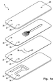
- FIG. 1a shows a static micromixer 1 with a cover plate 21, a mixer plate 20, a distributor plate 26 and a bottom plate 22 each separated from each other in a perspective view.
- the cover plate 21, the mixer plate 20 and the distributor plate 26 have a supply 23 for the fluid A and a supply 24 for the Fluid B in the form of a hole.
- the holes are arranged such that when stacking the plates, the feeds 23, 24 with the Feed structures 23, 24 of the bottom plate 22 fluidly in communication stand.
- the supply 23 for the fluid A and the supply 24 for the fluid B are arranged in the form of grooves on the bottom plate 22 such that the Fluid A to the manifold structure 27 and the fluid B to the manifold structure 28th the overlying distributor plate 26 without significant pressure losses can be directed.
- the distributor plate 26 has a distributor structure 27 for the fluid A and a distributor structure 28 for the fluid B in each case in the form a series of holes passing through the plate.
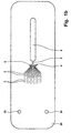
- the mixer plate 20 shown in detail in Figure 1 b in plan view has Fluid channels 2,3, an inlet chamber 4, a focusing channel 5 and a Expansion chamber 6 on.
- the discharge 25 in the form of a hole in the Cover plate 21 is arranged such that when stacking the plates the discharge 25 with the expansion chamber 6 of the mixer plate 20 fluidly communicates.
- the channels 2 for the fluid A have a smaller length as the channels 3 for the fluid B on.
- the channels 2, 3 are in their from the Inlet chamber 4 opposite side aligned parallel to each other, wherein the Channels 2 for the fluid A alternately adjacent to the channels 3 for the Fluid B lie. In a transition area, the distance of the Channels towards each other in the direction of inlet chamber 4.
- the channels 2, 3 In the area of Entrance into the inlet chamber 4, the channels 2, 3 in turn parallel aligned with each other. To ensure a uniform volume flow over all Channels 2, 3 for each to achieve a fluid, the channels 2, 3 respectively with each other the same length. This leads to that of the Entry chamber 4 remote ends of the fluid channels 2, 3 respectively to lie in a bow.
- the holes of the distributor structures 27,28 of Distributor plate 26 are also arranged in an arc in each case, that the ends of the channels 2, 3 each fluidly contacted with a bore become.
- the inlet chamber 4, in which the fluid channels 2, 3 open, points in the plane of the fluid channels on a half-concave shape.
- the concave surface 8 which the junctions of the fluid channels 2, 3rd opposite, the inlet chamber 4 is in the focusing channel 5 via.
- the focusing channel 5 opens into the expansion chamber 6, which of a wider in comparison with the focusing channel 5 and in Elongated to this arranged channel is formed.
- the structures of Fluid channels 2, 3, the inlet chamber 4, the focusing channel 5 and the Expansion chamber 6 are characterized by the material of the mixer plate 20th formed through openings. Through the underlying Distributor plate 26 and the overlying cover plate 21, these become two Side open structures forming channels or chambers covered.
- the united Fluid flows quickly transferred to the focusing channel 5.
- the thus formed focused total fluid flow is in the expansion chamber 6 as a fluid jet initiated.
- the formed mixture of fluids A, B is through which the discharge area of the expansion chamber 6 located exhaust hole 25th the cover plate 21 derived.
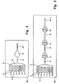
- FIG. 2 shows a mixer plate 20 in plan view, with the feeding ones Fluid channels 2,3 for the fluids A and B compared to Figure 1 b simplified are shown.
- the inlet chamber 4 has a semi-concave shape, wherein the concave surface 8 lies opposite the junctions of the channels 2, 3.
- the Inlet chamber 4 is in the region of the center of the concave surface 8 in the Focusing channel 5 via.
- the focusing channel 5 has over its entire Length equal to a width and opens into the expansion chamber 6 a.
- the Expansion chamber 6 is opposite to the focusing channel 5 in a further focusing channel 5 'which serves as outlet channel 7 via.
- the Expansion chamber 6 has a substantially circular in plan view Shape, which is widened in the direction of the further focusing channel 5 '. Due to this shape, the expansion chamber 6 has in its interior in the level shown adapted to the formation of stationary vertebrae Shape. This avoids dead water areas so that all areas of the Expansion chamber 6 are constantly flowed through
- the fluid streams of the fluids A and B emerging from the channels 2, 3 become merged in the inlet chamber 4 and, due to the schkonkave Form, quickly as a unified fluid lamella in the focusing channel. 5 transferred.
- Due to the much narrower cross section of the Focusing channel 5 compared to the inlet chamber 4 is a Focusing the fluid flow, i. a reduction in the fluid blade width achieved while increasing the flow rate.
- the so focused total fluid flow occurs as a fluid jet 5 in the expansion chamber. 6 and experiences there a lateral expansion, whereby on both sides of the Fluid jet can form vortices. That scored in the expansion chamber 6 Mixed product is re-focused in the further Focusing channel 5 'derived.
- the obtained fluid mixture is at the end of another focusing channel 5 'up into a above the mixer plate 20 located cover plate derived.
- the mixer plate 20 shown in plan view in Figure 3 has a series of a plurality of successively arranged expansion chambers 6, 6 ', 6 "and Focusing channels 5, 5 ', 5 ", 5'” on.
- the design and form of supplying fluid channels 2, 3, the inlet chamber 4, the focusing channel 5 and the expansion chamber 6 are equal to the corresponding structures the mixer plate previously shown in Figure 2.
- the expansion chamber 6 goes opposite the focusing channel 5 in another Focusing channel 5 'across, extending in the longitudinal extension of the Focusing channel 5 is located.
- This further focusing channel 5 ' opens turn into another vortex chamber 6 ', which in turn into a is followed by a further focusing channel 5 '" Expansion chamber 6 '", which finally serving as the outlet 7 the focusing channels 5, 5 ', 5 ", 5 “'have a substantially equal length and are in Longitudinal extension to each other with expansion chambers in between 6, 6 ', 6 "are arranged in the expansion chambers 6, 6', 6" of the fluid jet indicated by an arrow. On both sides of the fluid jet here formed by helical lines indicated steady vortex.
- the arranged behind an expansion chamber focusing channel detected thus at least part of the entering into the expansion chamber Fluid jet as well as a part of the obtained mixed product.
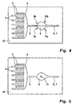
- the mixer plate 20 of another invention static micromixer shown in plan view.
- two Feed channels 9a, 9b In the expansion chamber 6 open on the side in which the Focusing channel 5 enters, and arranged symmetrically thereto, two Feed channels 9a, 9b.
- these feed channels 9a, 9b can in the area the formed vortex in the expansion chamber 6 another fluid, For example, be initiated an emulsifier.
- FIG. 5 shows a plan view of a mixer plate 20 of another static micromixer according to the invention having structures as in FIG. 2 shown, wherein additionally in the expansion chamber 6, a baffle structure 11th located.
- the baffle structure 11 is characterized by a in the expansion chamber. 6 formed cuboid structure, wherein one surface of the cuboid Opposite and spaced to the junction of the focusing channel. 5 located. This ensures that the fluid jet in the Expansion chamber 6 exiting focused total fluid flow on the Impingement 11 meets and there under vortex formation on both sides in the Expansion chamber 6 is derived. This is a particularly intimate Mixture achieved with very short mixing times.
- the formed mixture becomes via the further focusing channel 5 'serving as outlet channel 7 derived.
- a mixer plate 20 of a further embodiment of the invention static micromixer is shown in Figure 6 in plan view.
- the Arrangement of the fluid channels 2, 3, the inlet chamber 4 and the Focusing channel 5 corresponds to the figure 2.
- the focusing channel 5 goes in an expansion chamber 6 on, in the plane shown no Outlet channel has.
- the expansion chamber 6 points in the plane shown a substantially round shape, wherein the focusing channel. 5 opposite surface is arched into the expansion chamber. This ensures that the from the focusing channel 5 in the Expansion chamber 6 exiting fluid jet to the area of bulged Surface, which serves as a baffle structure 11, meets and on both sides in the Expansion chamber 6 is derived.
- the mixture thus obtained is through a located in the cover plate not shown outlet duct 7, which is shown here as a circle with a dashed line.
- FIG. 7 shows a variant of the mixer plate 20 of FIG. 6 illustrated static micromixer. Also here has the Expansion chamber 6 a through an area bulged in the chamber the wall of the expansion chamber 6 formed baffle structure 11. In the Expansion chamber 6 open two outlet channels 10a, 10b. These Outlet channels are located substantially opposite the Baffle structure 11 and are symmetrical to the axis of the focusing channel fifth arranged. Compared to Figure 6, the obtained mixture is thus not upward from the expansion chamber but laterally from the areas of the Vortex formation derived.
- FIG. 8 shows a variant of the embodiment shown in FIG shown.
- the expansion chamber 6 open in addition to the other Outlet channels 10a, 10b two supply channels 9a, 9b.
- These feed channels are on both sides of the baffle structure 11 and adjacent thereto as well symmetrical to the axis formed by the focusing channel 5 arranged.
- these feed channels can be the Supplying a mixture, in particular the emulsion or dispersion, supporting fluid, for example, the supply of an emulsifier, serve.
- the further outlet channels 10a, 10b and the feed channels 9a, 9b stand with appropriate feed or outlet structures in the soil and / or or cover plate in fluid communication.
- a mixer plate 20 of another embodiment of the static Micromixer is shown in Figure 9 in plan view.
- a common expansion chamber 16 open opposite of two sides two focusing channels 5, 15 a.
- These focusing channels 5, 15 are in Connection in each case with an inlet chamber 4, 14, in which the fluid channels 2,3; 12,13 lead.
- the two focusing channels 5, 15 are in Longitudinal extension arranged to each other. Perpendicular to this and in the same Level opens on both sides of an outlet 10 a, 10 b in the Expansion chamber 16.
- Both in the inlet chamber 4 and in the Inlet chamber 14 are from the fluid channels 2,3; 12,13 exit Fluid streams combined and rapidly focused into the focusing channel 5, 15 headed.
- the so united and focused fluid lamellae occur from the focusing channels 5,15 each as a fluid jet of on opposite sides in the common expansion chamber 16 and meet there under vortex formation on each other, which in a short time a intimate mixture is achieved.
- the obtained mixed product becomes on both sides from the common expansion chamber 16 via the outlet channels 10a, 10b, those with corresponding structures in the bottom and / or top plate fluidically derived.
- the static micromixer shown in Figures 1 a and 1 b was realized by means of microstructured glass plates.
- the mixer plate 20 and the Distributor plate 26 each had a thickness of 150 microns and the final bottom plate 22 and cover plate 21 each have a thickness of 1 mm up.
- the mixer plate 20th and the distributor plate 26 were holes with a diameter of 1.6 mm selected.
- the distributor plate 26 had two distributor structures 27, 28 Rows of 15 slots each with a length of 0.6 mm and a width of 0.2 mm.
- the fluid channels 2, 3 of the mixer plate 20 had a width of 60 microns at a length of 11.3 mm and a length of 7.3 mm.
- the distance between the junction of the Fluid channels 2, 3 and the mouth of the focusing channel 5 was only 2.5 mm, to rapidly divert and focus the combined fluid streams to enable.
- the ratio of the cross sectional area of the Focusing channel to the sum of the cross-sectional areas of the Fludikanäle 2, 3 was 1 to 3.6. With a length of 2.5 mm of the focusing channel 5, a length to width ratio of 5 to 1 was achieved.
- the Focusing channel 5 went in the longitudinal direction in the channel-like design Expansion chamber 6 a length of 24.6 mm and a width of 2.8 mm above.
- the opening angle of the side surfaces of the expansion chambers 6 in Transition region between the expansion chamber 6 and the Focusing channel 5 was 126.7 °.
- the four shown in the figure 1 a Plates had an external dimension of 26 x 76 mm.
- the plates were photolithographically using photoimageable glass by means of of a known method, as described by Th. R. Dietrich, W. Ehrfeld, M. Lacher and B. Speit in microstructure products photoimageable glass, F & M 104 (1996) on pages 520 to 524 has been described.
- the plates became fluid by thermal bonding tightly connected.
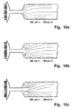
- FIGS. 10 a to 10 c only show the detail the junctions of the fluid channels 2, 3 in the inlet chamber 4, the Focusing channel 5 and the expansion chamber. 6
- the fluidized channels carrying the dye-added water are in the left entry area into the inlet chamber at its darker gray tone clearly visible. Since both the supplied silicone oil and the between the fluid channels 2, 3 existing webs of glass are transparent, These are not distinguishable here.
Landscapes
- Chemical & Material Sciences (AREA)
- Chemical Kinetics & Catalysis (AREA)
- Dispersion Chemistry (AREA)
- Organic Chemistry (AREA)
- Engineering & Computer Science (AREA)
- Computer Hardware Design (AREA)
- Microelectronics & Electronic Packaging (AREA)
- Accessories For Mixers (AREA)
Claims (23)
- Procédé pour le mélange d'au moins deux fluides comprenant les étapes consistant à :caractérisé par les étapes consistant à:Réunir plusieurs flux de fluide séparés de deux fluides d'une largeur s'inscrivant à chaque fois entre 1 µm et 1 mm et d'une profondeur s'inscrivant dans une plage de 10 µm à 1 mm en formant des lamelles de fluide alternativement voisines des deux fluides,Eliminer les flux de fluide réunis en formant un flux de fluides commun,Introduire le flux de fluides commun focalisé comme un faisceau fluide dans une chambre d'expansion (6) présentant une surface de section supérieure au flux de fluide commun focalisé perpendiculairement au sens d'écoulement du flux de fluide commun focalisé,A détourner le mélange formé.
- Procédé selon la revendication 1, caractérisé en ce que les flux de fluide réunis sont focalisés de sorte à ce que le comportement de la surface de la section des flux de fluide commun focalisé corresponde à la somme de la surface de la section des flux de fluide à réunir, à chaque fois de manière perpendiculaire au sens d'écoulement, dans une plage de 1 : 1,5 à 1 : 500, de préférence, dans une plage de 1 : 2 jusqu'à 1 : 50.
- Procédé selon l'une quelconque des revendications 1 à 2, caractérisé en ce que le rapport de la longueur du flux de fluide commun focalisé par rapport à sa largeur se trouve dans une plage de 1 : 1 à 30 : 1, de préférence, dans une plage de 1,5 : 1 à 10 : 1.
- Procédé selon l'une quelconque des revendications précédentes, caractérisé en ce que le flux de fluide commun focalisé est introduit comme faisceau de fluide dans une chambre d'expansion (6), de telle sorte que des volutes stationnaires se forment au moins dans un niveau par rapport aux deux côtés du faisceau de fluide.
- Procédé selon l'une quelconque des revendications précédentes, caractérisé en ce qu'au moins une partie du flux de fluide est détournée après l'introduction dans la chambre d'expansion (6), de nouveau sous focalisation.
- Procédé selon l'une quelconque des revendications précédentes, caractérisé par une réalisation répétée plusieurs fois ou une seule fois des deux étapes du procédé suivantes consistant à :le mélange formé étant détourné au cours de l'étape suivante.éliminer au moins une partie du flux de fluide après l'introduction préalable dans la chambre d'expansion (6) en formant un flux de fluide focalisé,introduire le flux de fluide focalisé dans une autre chambre d'expansion (6', 6") avec un flux de fluide présentant une surface de section supérieure dans la direction du flux de fluide focalisé perpendiculairement au sens d'écoulement du flux de fluide focalisé,
- Procédé selon l'une quelconque des revendications précédentes, caractérisé en ce qu'un autre fluide est introduit dans la chambre d'expansion, par exemple, un fluide présentant un adjuvant stabilisant le mélange.
- Procédé selon l'une quelconque des revendications précédentes, caractérisé en ce qu'au moins une partie du mélange formé est détournée à partir du domaine ou des domaines de la chambre d'expansion au moyen de la formation de volutes.
- Procédé selon l'une quelconque des revendications précédentes, caractérisé en ce que les deux premières étapes du procédé sont exécutées à chaque fois simultanément et séparément l'une de l'autre dans l'espace à deux ou plusieurs reprises, et en ce que les deux ou plusieurs flux de fluide communs focalisés ainsi obtenus sont introduits dans la chambre d'expansion commune.
- Micromélangeur statique (1) destiné au mélange d'au moins deux fluides présentant une multitude de canaux de fluide alternativement voisins (2, 3) d'une largeur s'inscrivant dans une plage de 1 µm à 1 mm, et d'une profondeur s'inscrivant dans une plage de 10 µm à 10 mm, pour l'alimentation séparée de fluides en tant que flux de fluide,
une chambre d'admission (4), dans laquelle débouchent les canaux de fluide,
un canal de focalisation (5) en contact par l'intermédiaire d'un fluide avec la chambre d'admission (4) pour l'élimination des flux de fluide unifiés dans la chambre d'admission (4) en formant un flux de fluide commun focalisé,
caractérisé en ce que
une chambre d'expansion (6), dans laquelle débouche le canal de focalisation (5) et dans laquelle le flux de fluide commun focalisé peut survenir comme faisceau fluide, présentant une surface de section supérieure au niveau du canal de focalisation (4), perpendiculairement à l'axe du canal de focalisation (4), et
au moins un canal d'évacuation (7) en contact avec la chambre d'expansion (6) au moyen d'un fluide pour détourner le mélange formé. - Micromélangeur statique selon la revendication 10, caractérisé en ce que la chambre d'admission (4) présente une forme concave ou demi-concave dans sa partie interne, au moins dans un niveau, laquelle forme comprend une surface concave (8) dans laquelle le canal de focalisation (5) débouche en son milieu face à la surface sur laquelle les canaux de fluide débouchent.
- Micromélangeur statique selon la revendication 10 ou 11, caractérisé en ce que le rapport de la surface de section des canaux de focalisation (5) par rapport à la somme de la surface de la section des canaux de fluide (2, 3) débouchant dans la chambre d'admission (4), à chaque fois de façon perpendiculaire par rapport à l'axe du canal, se trouve dans une plage de 1 : 1,5 à 1 : 500, de préférence, dans une plage de 1 : 2 à 1 : 50.
- Micromélangeur statique selon l'une quelconque des revendications 10 à 12, caractérisé en ce que le rapport de la longueur du canal de focalisation (5) par rapport à sa largeur s'inscrit dans une plage de 1 : 1 à 30 : 1, de préférence, dans une plage de 1,5 : 1 à 10 : 1.
- Micromélangeur statique selon l'une quelconque des revendications 10 à 13, caractérisé en ce que le rapport de la surface de section de la chambre d'expansion (6) dans au moins un domaine intermédiaire par rapport à la surface de la section du canal de focalisation (5) débouchant dans la chambre d'expansion perpendiculairement à l'axe du canal s'inscrit dans une plage de 1,5 : 1 à 500 : 1, de préférence, dans une plage de 2 : 1 à 50 : 1.
- Micromélangeur statique selon l'une quelconque des revendications 10 à 14, caractérisé en ce que la chambre d'expansion (6) fusionne dans un autre canal de focalisation (5') servant de canal de sortie (7) pour détourner et focaliser de nouveau au moins une partie du flux de fluide commun.
- Micromélangeur statique selon l'une quelconque des revendications 10 à 15, caractérisé par une succession d'un ou de plusieurs autres canaux de focalisation (5', 5"), dans lesquels la chambre d'expansion précédente fusionne à chaque fois (6, 6', 6") pour détourner et focaliser au moins une partie du flux de fluide commun et, d'une ou plusieurs autres chambres d'expansion (6', 6") dans lesquelles l'autre canal de focalisation (5', 5") précédent débouche à chaque fois, et
au moins un canal de sortie (7) lié par un fluide à la suite de la dernière chambre d'expansion (6") pour détourner le mélange formé. - Micromélangeur statique selon l'une quelconque des revendications 10 à 16, caractérisé en ce qu'un ou plusieurs canaux d'alimentation (9a, 9b) débouche(nt) dans la chambre d'expansion (6) pour amener un autre fluide, par exemple, un fluide présentant un adjuvant stabilisant le mélange.
- Micromélangeur statique selon l'une quelconque des revendications 10 à 17, caractérisé par un ou plusieurs autres canaux de sortie (10a, 10b) relié avec la chambre d'expansion (6) pour détourner le mélange formé.
- Micromélangeur statique selon l'une quelconque des revendications 10 à 18, caractérisé par une structure à impact (11) agencée dans la chambre d'expansion (6) pour détourner le faisceau de fluide.
- Micromélangeur statique selon l'une quelconque des revendications 10 à 19, caractérisé en ce que les nombreux canaux de fluide voisins (2, 3 ; 12, 13), la chambre d'admission (4 ; 14), dans laquelle les canaux de fluide (2, 3 ; 12, 13) débouchent, et le canal de focalisation (5 ; 15) relié, par l'intermédiaire d'un fluide, avec la chambre d'admission (4 ; 14) existe à chaque fois en deux ou plusieurs exemplaires et les deux ou plusieurs canaux de focalisation (5 ; 15) débouchent dans l'une des chambres d'expansion communes (16).
- Micromélangeur statique selon l'une quelconque des revendications 10 à 20, caractérisé en ce que les structures des canaux de fluide (2, 3), de la chambre d'admission (4), du canal de focalisation (5) et de la chambre d'expansion (6) sont utilisés comme des entailles et/ou des ruptures dans une plaque servant de plaque de mélange (20) composée d'un matériau suffisamment inerte pour les fluides à mélanger et ces structures ouvertes sont obturées par une plaque de fond et/ou une plaque de recouvrement de façon étanche aux fluides avec une plaque de mélange, la plaque de recouvrement et la plaque de fond (21, 22) présentant des alimentations (23, 24) pour les deux fluides et/ou au moins une évacuation (25) pour le mélange formé.
- Micromélangeur statique selon la revendication 21, caractérisé par une plaque de répartition liée de façon étanche aux fluides avec celui-ci et agencée entre la plaque de mélange (21) et la plaque de fond (22), pour amener de façon séparée les fluides depuis les alimentations se trouvant dans la plaque de fond (22) vers les canaux de fluide (2, 3) dans la plaque de mélange (20).
- Micromélangeur statique selon l'une quelconque des revendications 21 ou 22, caractérisé en ce qu'au moins la plaque de mélange (20) et la plaque de recouvrement et/ou de fond (23, 24) se composent d'un matériau transparent, notamment de verre ou de verre de quartz.
Applications Claiming Priority (3)
| Application Number | Priority Date | Filing Date | Title |
|---|---|---|---|
| DE10041823A DE10041823C2 (de) | 2000-08-25 | 2000-08-25 | Verfahren und statischer Mikrovermischer zum Mischen mindestens zweier Fluide |
| DE10041823 | 2000-08-25 | ||
| PCT/EP2001/009728 WO2002016017A2 (fr) | 2000-08-25 | 2001-08-23 | Procede et micromelangeur statique destines au melange d'au moins deux fluides |
Publications (2)
| Publication Number | Publication Date |
|---|---|
| EP1311341A2 EP1311341A2 (fr) | 2003-05-21 |
| EP1311341B1 true EP1311341B1 (fr) | 2004-06-16 |
Family
ID=7653784
Family Applications (1)
| Application Number | Title | Priority Date | Filing Date |
|---|---|---|---|
| EP01980263A Expired - Lifetime EP1311341B1 (fr) | 2000-08-25 | 2001-08-23 | Procede et micromelangeur statique destines au melange d'au moins deux fluides |
Country Status (6)
| Country | Link |
|---|---|
| US (1) | US6935768B2 (fr) |
| EP (1) | EP1311341B1 (fr) |
| AT (1) | ATE269149T1 (fr) |
| AU (1) | AU2002212151A1 (fr) |
| DE (2) | DE10041823C2 (fr) |
| WO (1) | WO2002016017A2 (fr) |
Cited By (24)
| Publication number | Priority date | Publication date | Assignee | Title |
|---|---|---|---|---|
| US6969505B2 (en) | 2002-08-15 | 2005-11-29 | Velocys, Inc. | Process for conducting an equilibrium limited chemical reaction in a single stage process channel |
| US7000427B2 (en) | 2002-08-15 | 2006-02-21 | Velocys, Inc. | Process for cooling a product in a heat exchanger employing microchannels |
| US7029647B2 (en) | 2004-01-27 | 2006-04-18 | Velocys, Inc. | Process for producing hydrogen peroxide using microchannel technology |
| US7084180B2 (en) | 2004-01-28 | 2006-08-01 | Velocys, Inc. | Fischer-tropsch synthesis using microchannel technology and novel catalyst and microchannel reactor |
| US7220390B2 (en) | 2003-05-16 | 2007-05-22 | Velocys, Inc. | Microchannel with internal fin support for catalyst or sorption medium |
| US7250074B2 (en) | 2003-08-29 | 2007-07-31 | Velocys, Inc. | Process for separating nitrogen from methane using microchannel process technology |
| US7294734B2 (en) | 2003-05-02 | 2007-11-13 | Velocys, Inc. | Process for converting a hydrocarbon to an oxygenate or a nitrile |
| US7305850B2 (en) | 2004-07-23 | 2007-12-11 | Velocys, Inc. | Distillation process using microchannel technology |
| US7307104B2 (en) | 2003-05-16 | 2007-12-11 | Velocys, Inc. | Process for forming an emulsion using microchannel process technology |
| DE102007020243A1 (de) | 2007-04-24 | 2008-10-30 | INSTITUT FüR MIKROTECHNIK MAINZ GMBH | Akustische Misch- und/oder Fördervorrichtung und Probenaufbereitungschip mit einem solchen |
| US7485671B2 (en) | 2003-05-16 | 2009-02-03 | Velocys, Inc. | Process for forming an emulsion using microchannel process technology |
| US7610775B2 (en) | 2004-07-23 | 2009-11-03 | Velocys, Inc. | Distillation process using microchannel technology |
| US7780944B2 (en) | 2002-08-15 | 2010-08-24 | Velocys, Inc. | Multi-stream microchannel device |
| US7816411B2 (en) | 2004-10-01 | 2010-10-19 | Velocys, Inc. | Multiphase mixing process using microchannel process technology |
| US7935734B2 (en) | 2005-07-08 | 2011-05-03 | Anna Lee Tonkovich | Catalytic reaction process using microchannel technology |
| US8383872B2 (en) | 2004-11-16 | 2013-02-26 | Velocys, Inc. | Multiphase reaction process using microchannel technology |
| US8580211B2 (en) | 2003-05-16 | 2013-11-12 | Velocys, Inc. | Microchannel with internal fin support for catalyst or sorption medium |
| US8703984B2 (en) | 2004-08-12 | 2014-04-22 | Velocys, Inc. | Process for converting ethylene to ethylene oxide using microchannel process technology |
| US8747805B2 (en) | 2004-02-11 | 2014-06-10 | Velocys, Inc. | Process for conducting an equilibrium limited chemical reaction using microchannel technology |
| US9006298B2 (en) | 2012-08-07 | 2015-04-14 | Velocys, Inc. | Fischer-Tropsch process |
| US9023900B2 (en) | 2004-01-28 | 2015-05-05 | Velocys, Inc. | Fischer-Tropsch synthesis using microchannel technology and novel catalyst and microchannel reactor |
| US9101890B2 (en) | 2005-05-25 | 2015-08-11 | Velocys, Inc. | Support for use in microchannel processing |
| US9150494B2 (en) | 2004-11-12 | 2015-10-06 | Velocys, Inc. | Process using microchannel technology for conducting alkylation or acylation reaction |
| WO2016170075A1 (fr) | 2015-04-24 | 2016-10-27 | Fraunhofer-Gesellschaft zur Förderung der angewandten Forschung e.V. | Procédé de conversion électrochimique d'acides gras et système de mise en œuvre du procédé |
Families Citing this family (136)
| Publication number | Priority date | Publication date | Assignee | Title |
|---|---|---|---|---|
| US20110075507A1 (en) * | 1997-10-24 | 2011-03-31 | Revalesio Corporation | Diffuser/emulsifier |
| US7654728B2 (en) | 1997-10-24 | 2010-02-02 | Revalesio Corporation | System and method for therapeutic application of dissolved oxygen |
| US7128278B2 (en) | 1997-10-24 | 2006-10-31 | Microdiffusion, Inc. | System and method for irritating with aerated water |
| US6386751B1 (en) * | 1997-10-24 | 2002-05-14 | Diffusion Dynamics, Inc. | Diffuser/emulsifier |
| US6702949B2 (en) | 1997-10-24 | 2004-03-09 | Microdiffusion, Inc. | Diffuser/emulsifier for aquaculture applications |
| US7708749B2 (en) | 2000-12-20 | 2010-05-04 | Fox Hollow Technologies, Inc. | Debulking catheters and methods |
| US8328829B2 (en) | 1999-08-19 | 2012-12-11 | Covidien Lp | High capacity debulking catheter with razor edge cutting window |
| US7713279B2 (en) | 2000-12-20 | 2010-05-11 | Fox Hollow Technologies, Inc. | Method and devices for cutting tissue |
| US6299622B1 (en) | 1999-08-19 | 2001-10-09 | Fox Hollow Technologies, Inc. | Atherectomy catheter with aligned imager |
| ES2436668T3 (es) | 2000-12-20 | 2014-01-03 | Covidien Lp | Catéter para retirar material oclusivo ateromatoso o trombótico |
| DE10123092B4 (de) * | 2001-05-07 | 2005-02-10 | INSTITUT FüR MIKROTECHNIK MAINZ GMBH | Verfahren und statischer Mischer zum Mischen mindestens zweier Fluide |
| DE10123093A1 (de) * | 2001-05-07 | 2002-11-21 | Inst Mikrotechnik Mainz Gmbh | Verfahren und statischer Mikrovermischer zum Mischen mindestens zweier Fluide |
| JP2006507921A (ja) * | 2002-06-28 | 2006-03-09 | プレジデント・アンド・フェロウズ・オブ・ハーバード・カレッジ | 流体分散のための方法および装置 |
| JP4346893B2 (ja) | 2002-11-01 | 2009-10-21 | 株式会社日立製作所 | 化学反応装置 |
| DE20218972U1 (de) | 2002-12-07 | 2003-02-13 | Ehrfeld Mikrotechnik Ag | Statischer Laminationsmikrovermischer |
| GB0307403D0 (en) | 2003-03-31 | 2003-05-07 | Medical Res Council | Selection by compartmentalised screening |
| GB0307428D0 (en) | 2003-03-31 | 2003-05-07 | Medical Res Council | Compartmentalised combinatorial chemistry |
| US20060078893A1 (en) | 2004-10-12 | 2006-04-13 | Medical Research Council | Compartmentalised combinatorial chemistry by microfluidic control |
| EP3616781A1 (fr) | 2003-04-10 | 2020-03-04 | President and Fellows of Harvard College | Formation et régulation d'espèces fluidiques |
| US8246640B2 (en) | 2003-04-22 | 2012-08-21 | Tyco Healthcare Group Lp | Methods and devices for cutting tissue at a vascular location |
| DE10333921B4 (de) * | 2003-07-25 | 2005-10-20 | Wella Ag | Extraktionsverfahren unter Verwendung eines statischen Mikromischers |
| DE10333922B4 (de) * | 2003-07-25 | 2005-11-17 | Wella Ag | Bauteile für statische Mikromischer, daraus aufgebaute Mikromischer und deren Verwendung zum Mischen, zum Dispergieren oder zur Durchführung chemischer Reaktionen |
| CN104069784B (zh) | 2003-08-27 | 2017-01-11 | 哈佛大学 | 流体物种的电子控制 |
| AU2004203870B2 (en) * | 2003-09-17 | 2011-03-03 | Fisher & Paykel Healthcare Limited | Breathable Respiratory Mask |
| EP1525917A1 (fr) * | 2003-10-23 | 2005-04-27 | F. Hoffmann-La Roche Ag | Dispositif microfluidique avec traversée |
| DE102004007708A1 (de) * | 2004-02-16 | 2005-08-25 | Dynamit Nobel Gmbh Explosivstoff- Und Systemtechnik | Verfahren zur Aufarbeitung von flüssigen Stoffen |
| JP4547606B2 (ja) * | 2004-03-17 | 2010-09-22 | 富士フイルム株式会社 | マイクロリアクターの複合反応方法及びマイクロリアクター |
| US20050221339A1 (en) * | 2004-03-31 | 2005-10-06 | Medical Research Council Harvard University | Compartmentalised screening by microfluidic control |
| EP1944079B1 (fr) * | 2004-06-11 | 2012-05-30 | Corning Incorporated | Conceptions de microstructures pour optimiser le mélange et la chute de pression |
| US9477233B2 (en) | 2004-07-02 | 2016-10-25 | The University Of Chicago | Microfluidic system with a plurality of sequential T-junctions for performing reactions in microdroplets |
| US7968287B2 (en) | 2004-10-08 | 2011-06-28 | Medical Research Council Harvard University | In vitro evolution in microfluidic systems |
| EP1830952A2 (fr) * | 2004-11-17 | 2007-09-12 | Velocys Inc. | Procede de formation d'emulsions par la technique des microcanaux |
| DE102004062076A1 (de) * | 2004-12-23 | 2006-07-06 | Forschungszentrum Karlsruhe Gmbh | Statischer Mikrovermischer |
| DE102004062074A1 (de) * | 2004-12-23 | 2006-07-06 | Forschungszentrum Karlsruhe Gmbh | Statischer Mikrovermischer |
| DE102005000835B3 (de) * | 2005-01-05 | 2006-09-07 | Advalytix Ag | Verfahren und Vorrichtung zur Dosierung kleiner Flüssigkeitsmengen |
| US20070054119A1 (en) * | 2005-03-04 | 2007-03-08 | Piotr Garstecki | Systems and methods of forming particles |
| EP2248578B1 (fr) | 2005-03-04 | 2012-06-06 | President and Fellows of Harvard College | Procédé pour former des émulsions multiples |
| DE102005015433A1 (de) | 2005-04-05 | 2006-10-12 | Forschungszentrum Karlsruhe Gmbh | Mischersystem, Reaktor und Reaktorsystem |
| JP2006320772A (ja) * | 2005-05-17 | 2006-11-30 | Hitachi Plant Technologies Ltd | マイクロ流体デバイス |
| DE102005037401B4 (de) | 2005-08-08 | 2007-09-27 | MAX-PLANCK-Gesellschaft zur Förderung der Wissenschaften e.V. | Bildung einer Emulsion in einem fluidischen Mikrosystem |
| US20090268548A1 (en) * | 2005-08-11 | 2009-10-29 | Eksigent Technologies, Llc | Microfluidic systems, devices and methods for reducing diffusion and compliance effects at a fluid mixing region |
| JP2007121275A (ja) * | 2005-09-27 | 2007-05-17 | Fujifilm Corp | マイクロチップ、このマイクロチップを用いた液体の混合方法及び血液検査方法 |
| JP2009536313A (ja) | 2006-01-11 | 2009-10-08 | レインダンス テクノロジーズ, インコーポレイテッド | ナノリアクターの形成および制御において使用するマイクロ流体デバイスおよび方法 |
| JP4713397B2 (ja) * | 2006-01-18 | 2011-06-29 | 株式会社リコー | 微小流路構造体及び微小液滴生成システム |
| CA2640024A1 (fr) * | 2006-01-27 | 2007-08-09 | President And Fellows Of Harvard College | Coalescence de gouttelettes fluidiques |
| AT503116B1 (de) * | 2006-03-17 | 2007-08-15 | Dbs Daily Business Support Sof | Mikroreaktor |
| US9562837B2 (en) | 2006-05-11 | 2017-02-07 | Raindance Technologies, Inc. | Systems for handling microfludic droplets |
| EP2530168B1 (fr) * | 2006-05-11 | 2015-09-16 | Raindance Technologies, Inc. | Dispositifs microfluidiques |
| US20070276419A1 (en) | 2006-05-26 | 2007-11-29 | Fox Hollow Technologies, Inc. | Methods and devices for rotating an active element and an energy emitter on a catheter |
| US20090073800A1 (en) * | 2006-07-11 | 2009-03-19 | Paradox Holding Company, Llc. | Apparatus and Method for Mixing Fluids at the Surface for Subterranean Treatments |
| DE102006036815B4 (de) * | 2006-08-07 | 2010-01-14 | MAX-PLANCK-Gesellschaft zur Förderung der Wissenschaften e.V. | Emulgiereinrichtung und Verfahren zur Bildung einer Emulsion |
| WO2008021123A1 (fr) | 2006-08-07 | 2008-02-21 | President And Fellows Of Harvard College | Tensioactifs fluorocarbonés stabilisateurs d'émulsions |
| EP1894617B1 (fr) * | 2006-08-31 | 2013-08-14 | Samsung Electronics Co., Ltd. | Procédé de mélange d'au moins deux types de fluides dans un substrat de traitement de microfluide à centrifuge |
| JP4677969B2 (ja) * | 2006-10-06 | 2011-04-27 | 株式会社日立プラントテクノロジー | マイクロリアクタ |
| US8445546B2 (en) | 2006-10-25 | 2013-05-21 | Revalesio Corporation | Electrokinetically-altered fluids comprising charge-stabilized gas-containing nanostructures |
| CA2667614A1 (fr) | 2006-10-25 | 2008-09-25 | Revalesio Corporation | Methodes de soins et de traitement de plaies |
| US8784898B2 (en) | 2006-10-25 | 2014-07-22 | Revalesio Corporation | Methods of wound care and treatment |
| AU2007308840C1 (en) | 2006-10-25 | 2014-09-25 | Revalesio Corporation | Methods of therapeutic treatment of eyes and other human tissues using an oxygen-enriched solution |
| AU2007308838B2 (en) | 2006-10-25 | 2014-03-13 | Revalesio Corporation | Mixing device and output fluids of same |
| US8609148B2 (en) | 2006-10-25 | 2013-12-17 | Revalesio Corporation | Methods of therapeutic treatment of eyes |
| US8784897B2 (en) | 2006-10-25 | 2014-07-22 | Revalesio Corporation | Methods of therapeutic treatment of eyes |
| NL1032816C2 (nl) * | 2006-11-06 | 2008-05-08 | Micronit Microfluidics Bv | Micromengkamer, micromenger omvattende meerdere van dergelijke micromengkamers, werkwijzen voor het vervaardigen daarvan, en werkwijzen voor mengen. |
| US8772046B2 (en) | 2007-02-06 | 2014-07-08 | Brandeis University | Manipulation of fluids and reactions in microfluidic systems |
| WO2008121342A2 (fr) * | 2007-03-28 | 2008-10-09 | President And Fellows Of Harvard College | Émulsions, et techniques de formation |
| WO2008130623A1 (fr) | 2007-04-19 | 2008-10-30 | Brandeis University | Manipulation de fluides, composants fluidiques et réactions dans des systèmes microfluidiques |
| EP1992404B1 (fr) * | 2007-05-15 | 2011-03-23 | Corning Incorporated | Dispositif microfluidique et procédé pour réactions de liquides immiscibles |
| EP2017000B1 (fr) * | 2007-07-11 | 2012-09-05 | Corning Incorporated | Dispositifs microfluidiques pour procédés intensifiés |
| US20100303918A1 (en) * | 2007-10-25 | 2010-12-02 | Revalesio Corporation | Compositions and methods for treating asthma and other lung disorders |
| US20100310665A1 (en) * | 2007-10-25 | 2010-12-09 | Revalesio Corporation | Bacteriostatic or bacteriocidal compositions and methods |
| US20100303871A1 (en) * | 2007-10-25 | 2010-12-02 | Revalesio Corporation | Compositions and methods for modulating cellular membrane-mediated intracellular signal transduction |
| US20100303917A1 (en) * | 2007-10-25 | 2010-12-02 | Revalesio Corporation | Compositions and methods for treating cystic fibrosis |
| US9523090B2 (en) | 2007-10-25 | 2016-12-20 | Revalesio Corporation | Compositions and methods for treating inflammation |
| US10125359B2 (en) | 2007-10-25 | 2018-11-13 | Revalesio Corporation | Compositions and methods for treating inflammation |
| US9745567B2 (en) | 2008-04-28 | 2017-08-29 | Revalesio Corporation | Compositions and methods for treating multiple sclerosis |
| US20090263495A1 (en) * | 2007-10-25 | 2009-10-22 | Revalesio Corporation | Bacteriostatic or bacteriocidal compositions and methods |
| US8784440B2 (en) | 2008-02-25 | 2014-07-22 | Covidien Lp | Methods and devices for cutting tissue |
| EP2285347A4 (fr) | 2008-05-01 | 2011-09-21 | Revalesio Corp | Compositions et méthodes de traitement de troubles digestifs |
| WO2010009365A1 (fr) | 2008-07-18 | 2010-01-21 | Raindance Technologies, Inc. | Bibliothèque de gouttelettes |
| JP5604038B2 (ja) * | 2008-08-25 | 2014-10-08 | 株式会社日立製作所 | 反応装置及び反応プラント |
| US8430558B1 (en) * | 2008-09-05 | 2013-04-30 | University Of Central Florida Research Foundation, Inc. | Microfluidic mixer having channel width variation for enhanced fluid mixing |
| EP2172260A1 (fr) * | 2008-09-29 | 2010-04-07 | Corning Incorporated | Dispositifs microfluidiques à flux multiple |
| US8414785B2 (en) * | 2008-10-02 | 2013-04-09 | California Institute Of Technology | Methods for fabrication of microfluidic systems on printed circuit boards |
| WO2010045226A2 (fr) | 2008-10-13 | 2010-04-22 | Fox Hollow Technologies, Inc. | Dispositifs et méthodes de manipulation d'un axe de cathéter |
| US20100098659A1 (en) * | 2008-10-22 | 2010-04-22 | Revalesio Corporation | Compositions and methods for treating matrix metalloproteinase 9 (mmp9)-mediated conditions |
| JP5116112B2 (ja) * | 2009-02-19 | 2013-01-09 | シャープ株式会社 | 流体混合装置及び流体混合方法 |
| EP3415235A1 (fr) | 2009-03-23 | 2018-12-19 | Raindance Technologies Inc. | Manipulation de gouttelettes microfluidiques |
| US8815292B2 (en) | 2009-04-27 | 2014-08-26 | Revalesio Corporation | Compositions and methods for treating insulin resistance and diabetes mellitus |
| AU2010241801B2 (en) | 2009-04-29 | 2013-04-11 | Covidien Lp | Methods and devices for cutting and abrading tissue |
| BRPI1010595A2 (pt) | 2009-05-14 | 2017-05-16 | Tyco Healthcare | cateteres de aterectomia facilmente limpaveis e metodos para uso |
| US20120211084A1 (en) | 2009-09-02 | 2012-08-23 | President And Fellows Of Harvard College | Multiple emulsions created using jetting and other techniques |
| WO2011042564A1 (fr) | 2009-10-09 | 2011-04-14 | Universite De Strasbourg | Nanomatériau marqué à base de silice à propriétés améliorées et ses utilisations |
| EP2506783B1 (fr) | 2009-12-02 | 2016-06-29 | Covidien LP | Procédés et dispositifs de coupe de tissu |
| KR101398384B1 (ko) | 2009-12-11 | 2014-05-23 | 코비디엔 엘피 | 물질 포획 효율이 향상된 물질 제거 장치 및 사용 방법 |
| US10837883B2 (en) | 2009-12-23 | 2020-11-17 | Bio-Rad Laboratories, Inc. | Microfluidic systems and methods for reducing the exchange of molecules between droplets |
| US9399797B2 (en) | 2010-02-12 | 2016-07-26 | Raindance Technologies, Inc. | Digital analyte analysis |
| JP5934657B2 (ja) | 2010-02-12 | 2016-06-15 | レインダンス テクノロジーズ, インコーポレイテッド | デジタル検体分析 |
| US9366632B2 (en) | 2010-02-12 | 2016-06-14 | Raindance Technologies, Inc. | Digital analyte analysis |
| US10351905B2 (en) | 2010-02-12 | 2019-07-16 | Bio-Rad Laboratories, Inc. | Digital analyte analysis |
| BR112012028540A2 (pt) | 2010-05-07 | 2016-07-26 | Revalesio Corp | composições e métodos para melhorar desempenho fisiológico e tempo de recuperação |
| US9119662B2 (en) | 2010-06-14 | 2015-09-01 | Covidien Lp | Material removal device and method of use |
| EP2594332B1 (fr) * | 2010-07-13 | 2020-03-04 | Tokyo Institute of Technology | Appareil pour la production de microgouttelettes de liquide |
| AU2011289172B2 (en) | 2010-08-12 | 2015-09-24 | Revalesio Corporation | Compositions and methods for treatment of taupathy |
| EP3447155A1 (fr) | 2010-09-30 | 2019-02-27 | Raindance Technologies, Inc. | Dosages en sandwich dans des gouttelettes |
| BR112013009835A2 (pt) | 2010-10-28 | 2016-07-26 | Covidien Lp | dispositivo para a remoção de material e método de uso |
| KR20150020240A (ko) | 2010-11-11 | 2015-02-25 | 코비디엔 엘피 | 촬영용 가요성 디벌킹 카테터와, 사용 및 제조 방법 |
| EP2457886B1 (fr) * | 2010-11-29 | 2014-04-02 | Corning Incorporated | Sulfonation dans des microréacteurs à flux continu |
| WO2012109600A2 (fr) | 2011-02-11 | 2012-08-16 | Raindance Technologies, Inc. | Procédés de formation de gouttelettes mélangées |
| JP2012166172A (ja) * | 2011-02-16 | 2012-09-06 | Dic Corp | 流体混合装置 |
| EP2675819B1 (fr) | 2011-02-18 | 2020-04-08 | Bio-Rad Laboratories, Inc. | Compositions et méthodes de marquage moléculaire |
| CN102188944B (zh) * | 2011-05-16 | 2013-08-28 | 利穗科技(苏州)有限公司 | 一种混沌型多级涡流微反应器 |
| CN102188943B (zh) * | 2011-05-16 | 2013-08-28 | 利穗科技(苏州)有限公司 | 一种撞击流多级微反应器 |
| US9238206B2 (en) | 2011-05-23 | 2016-01-19 | President And Fellows Of Harvard College | Control of emulsions, including multiple emulsions |
| EP2714970B1 (fr) | 2011-06-02 | 2017-04-19 | Raindance Technologies, Inc. | Quantification d'enzyme |
| US8841071B2 (en) | 2011-06-02 | 2014-09-23 | Raindance Technologies, Inc. | Sample multiplexing |
| EP2729238A2 (fr) | 2011-07-06 | 2014-05-14 | President and Fellows of Harvard College | Émulsions multiples et techniques de formation d'émulsions multiples |
| US8658430B2 (en) | 2011-07-20 | 2014-02-25 | Raindance Technologies, Inc. | Manipulating droplet size |
| CN102247787A (zh) * | 2011-08-01 | 2011-11-23 | 利穗科技(苏州)有限公司 | 一种混沌型微反应器 |
| WO2013033426A2 (fr) | 2011-09-01 | 2013-03-07 | Covidien Lp | Cathéter comportant une tige d'entraînement hélicoïdale et procédés de fabrication corrrespondants |
| US9533308B2 (en) | 2012-02-10 | 2017-01-03 | California Institute Of Technology | PC board-based polymerase chain reaction systems, methods and materials |
| US9579157B2 (en) | 2012-09-13 | 2017-02-28 | Covidien Lp | Cleaning device for medical instrument and method of use |
| US9943329B2 (en) | 2012-11-08 | 2018-04-17 | Covidien Lp | Tissue-removing catheter with rotatable cutter |
| US11901041B2 (en) | 2013-10-04 | 2024-02-13 | Bio-Rad Laboratories, Inc. | Digital analysis of nucleic acid modification |
| US9944977B2 (en) | 2013-12-12 | 2018-04-17 | Raindance Technologies, Inc. | Distinguishing rare variations in a nucleic acid sequence from a sample |
| WO2015103367A1 (fr) | 2013-12-31 | 2015-07-09 | Raindance Technologies, Inc. | Système et procédé de détection d'une espèce d'arn |
| WO2015200702A1 (fr) | 2014-06-27 | 2015-12-30 | Covidien Lp | Dispositif de nettoyage pour cathéter, et cathéter le comprenant |
| US10314667B2 (en) | 2015-03-25 | 2019-06-11 | Covidien Lp | Cleaning device for cleaning medical instrument |
| KR101689622B1 (ko) * | 2015-06-03 | 2016-12-26 | 인하대학교 산학협력단 | 사인파형 맥동유동을 이용한 축소-확대형 미세 혼합기 및 이를 이용한 유체 혼합 방법 |
| GB2554618B (en) | 2015-06-12 | 2021-11-10 | Velocys Inc | Synthesis gas conversion process |
| US10292721B2 (en) | 2015-07-20 | 2019-05-21 | Covidien Lp | Tissue-removing catheter including movable distal tip |
| US10647981B1 (en) | 2015-09-08 | 2020-05-12 | Bio-Rad Laboratories, Inc. | Nucleic acid library generation methods and compositions |
| US10314664B2 (en) | 2015-10-07 | 2019-06-11 | Covidien Lp | Tissue-removing catheter and tissue-removing element with depth stop |
| US11035480B2 (en) * | 2016-02-24 | 2021-06-15 | Leanna Levine and Aline, Inc. | Mechanically driven sequencing manifold |
| US20190126312A1 (en) * | 2017-11-01 | 2019-05-02 | Nanosys, Inc. | In-line mixing of nanostructure premixes for real-time white point adjustment |
| US11383236B2 (en) | 2017-11-10 | 2022-07-12 | Christopher Walker | Polymerase chain reaction using a microfluidic chip fabricated with printed circuit board techniques |
| EP3646941A3 (fr) | 2018-10-11 | 2020-12-30 | Emulco Laboratories C.V.B.A. | Procédé de production d'émulsions et émulsion aqueuse de polyisobutène |
| CN109464973B (zh) * | 2018-12-19 | 2024-03-08 | 上海璨谊生物科技有限公司 | 微通道模块 |
Family Cites Families (8)
| Publication number | Priority date | Publication date | Assignee | Title |
|---|---|---|---|---|
| US4534659A (en) * | 1984-01-27 | 1985-08-13 | Millipore Corporation | Passive fluid mixing system |
| DE19541266A1 (de) * | 1995-11-06 | 1997-05-07 | Bayer Ag | Verfahren und Vorrichtung zur Durchführung chemischer Reaktionen mittels eines Mikrostruktur-Lamellenmischers |
| EP1009520A4 (fr) * | 1997-01-24 | 2003-05-14 | Univ California | Appareil et procede de melange laminaire planaire |
| DE19741645A1 (de) | 1997-09-22 | 1999-03-25 | Bayer Ag | Verfahren und Vorrichtung zur Oxidation organischer Verbindungen in flüssiger Phase unter Verwendung peroxidischer Oxidationsmittel |
| DE19800529A1 (de) | 1998-01-09 | 1999-07-15 | Bayer Ag | Verfahren zur Phosgenierung von Aminen in der Gasphase unter Einsatz von Mikrostrukturmischern |
| DE19816886C2 (de) | 1998-04-17 | 2001-06-07 | Axiva Gmbh | Verfahren und Vorrichtung zur kontinuierlichen Herstellung von Polymerisaten |
| WO2000022436A1 (fr) * | 1998-10-13 | 2000-04-20 | Biomicro Systems, Inc. | Composants de circuit fluidique bases sur la dynamique passive des fluides |
| US6655829B1 (en) * | 2001-05-07 | 2003-12-02 | Uop Llc | Static mixer and process for mixing at least two fluids |
-
2000
- 2000-08-25 DE DE10041823A patent/DE10041823C2/de not_active Expired - Fee Related
-
2001
- 2001-08-23 AU AU2002212151A patent/AU2002212151A1/en not_active Abandoned
- 2001-08-23 AT AT01980263T patent/ATE269149T1/de not_active IP Right Cessation
- 2001-08-23 EP EP01980263A patent/EP1311341B1/fr not_active Expired - Lifetime
- 2001-08-23 US US10/344,717 patent/US6935768B2/en not_active Expired - Lifetime
- 2001-08-23 WO PCT/EP2001/009728 patent/WO2002016017A2/fr active IP Right Grant
- 2001-08-23 DE DE50102620T patent/DE50102620D1/de not_active Expired - Lifetime
Cited By (33)
| Publication number | Priority date | Publication date | Assignee | Title |
|---|---|---|---|---|
| US7255845B2 (en) | 2002-08-15 | 2007-08-14 | Velocys, Inc. | Process for conducting an equilibrium limited chemical reaction in a single stage process channel |
| US7000427B2 (en) | 2002-08-15 | 2006-02-21 | Velocys, Inc. | Process for cooling a product in a heat exchanger employing microchannels |
| US6969505B2 (en) | 2002-08-15 | 2005-11-29 | Velocys, Inc. | Process for conducting an equilibrium limited chemical reaction in a single stage process channel |
| US7780944B2 (en) | 2002-08-15 | 2010-08-24 | Velocys, Inc. | Multi-stream microchannel device |
| US9108904B2 (en) | 2003-05-02 | 2015-08-18 | Velocys, Inc. | Process for converting a hydrocarbon to an oxygenate or a nitrile |
| US7294734B2 (en) | 2003-05-02 | 2007-11-13 | Velocys, Inc. | Process for converting a hydrocarbon to an oxygenate or a nitrile |
| US7226574B2 (en) | 2003-05-16 | 2007-06-05 | Velocys, Inc. | Oxidation process using microchannel technology and novel catalyst useful in same |
| US7220390B2 (en) | 2003-05-16 | 2007-05-22 | Velocys, Inc. | Microchannel with internal fin support for catalyst or sorption medium |
| US8580211B2 (en) | 2003-05-16 | 2013-11-12 | Velocys, Inc. | Microchannel with internal fin support for catalyst or sorption medium |
| US7307104B2 (en) | 2003-05-16 | 2007-12-11 | Velocys, Inc. | Process for forming an emulsion using microchannel process technology |
| US7485671B2 (en) | 2003-05-16 | 2009-02-03 | Velocys, Inc. | Process for forming an emulsion using microchannel process technology |
| US7896935B2 (en) | 2003-05-16 | 2011-03-01 | Velocys, Inc. | Process of conducting reactions or separation in a microchannel with internal fin support for catalyst or sorption medium |
| US7250074B2 (en) | 2003-08-29 | 2007-07-31 | Velocys, Inc. | Process for separating nitrogen from methane using microchannel process technology |
| US7029647B2 (en) | 2004-01-27 | 2006-04-18 | Velocys, Inc. | Process for producing hydrogen peroxide using microchannel technology |
| US9453165B2 (en) | 2004-01-28 | 2016-09-27 | Velocys, Inc. | Fischer-tropsch synthesis using microchannel technology and novel catalyst and microchannel reactor |
| US7722833B2 (en) | 2004-01-28 | 2010-05-25 | Velocys, Inc. | Microchannel reactor |
| US7084180B2 (en) | 2004-01-28 | 2006-08-01 | Velocys, Inc. | Fischer-tropsch synthesis using microchannel technology and novel catalyst and microchannel reactor |
| US8188153B2 (en) | 2004-01-28 | 2012-05-29 | Velocys, Inc. | Fischer-Tropsch synthesis using microchannel technology and novel catalyst and microchannel reactor |
| US9023900B2 (en) | 2004-01-28 | 2015-05-05 | Velocys, Inc. | Fischer-Tropsch synthesis using microchannel technology and novel catalyst and microchannel reactor |
| US8747805B2 (en) | 2004-02-11 | 2014-06-10 | Velocys, Inc. | Process for conducting an equilibrium limited chemical reaction using microchannel technology |
| US7610775B2 (en) | 2004-07-23 | 2009-11-03 | Velocys, Inc. | Distillation process using microchannel technology |
| US7305850B2 (en) | 2004-07-23 | 2007-12-11 | Velocys, Inc. | Distillation process using microchannel technology |
| US8703984B2 (en) | 2004-08-12 | 2014-04-22 | Velocys, Inc. | Process for converting ethylene to ethylene oxide using microchannel process technology |
| US7816411B2 (en) | 2004-10-01 | 2010-10-19 | Velocys, Inc. | Multiphase mixing process using microchannel process technology |
| US9150494B2 (en) | 2004-11-12 | 2015-10-06 | Velocys, Inc. | Process using microchannel technology for conducting alkylation or acylation reaction |
| US8383872B2 (en) | 2004-11-16 | 2013-02-26 | Velocys, Inc. | Multiphase reaction process using microchannel technology |
| US9101890B2 (en) | 2005-05-25 | 2015-08-11 | Velocys, Inc. | Support for use in microchannel processing |
| US7935734B2 (en) | 2005-07-08 | 2011-05-03 | Anna Lee Tonkovich | Catalytic reaction process using microchannel technology |
| DE102007020243A1 (de) | 2007-04-24 | 2008-10-30 | INSTITUT FüR MIKROTECHNIK MAINZ GMBH | Akustische Misch- und/oder Fördervorrichtung und Probenaufbereitungschip mit einem solchen |
| US9006298B2 (en) | 2012-08-07 | 2015-04-14 | Velocys, Inc. | Fischer-Tropsch process |
| US9359271B2 (en) | 2012-08-07 | 2016-06-07 | Velocys, Inc. | Fischer-Tropsch process |
| WO2016170075A1 (fr) | 2015-04-24 | 2016-10-27 | Fraunhofer-Gesellschaft zur Förderung der angewandten Forschung e.V. | Procédé de conversion électrochimique d'acides gras et système de mise en œuvre du procédé |
| DE102015207581A1 (de) | 2015-04-24 | 2016-10-27 | Fraunhofer-Gesellschaft zur Förderung der angewandten Forschung e.V. | Verfahren zur elektrochemischen Umwandlung von Fettsäuren und Anlage zur Durchführung des Verfahrens |
Also Published As
| Publication number | Publication date |
|---|---|
| EP1311341A2 (fr) | 2003-05-21 |
| AU2002212151A1 (en) | 2002-03-04 |
| WO2002016017A2 (fr) | 2002-02-28 |
| WO2002016017A9 (fr) | 2002-09-19 |
| ATE269149T1 (de) | 2004-07-15 |
| WO2002016017A3 (fr) | 2002-05-23 |
| US6935768B2 (en) | 2005-08-30 |
| DE10041823C2 (de) | 2002-12-19 |
| US20040027915A1 (en) | 2004-02-12 |
| DE50102620D1 (de) | 2004-07-22 |
| DE10041823A1 (de) | 2002-03-14 |
Similar Documents
| Publication | Publication Date | Title |
|---|---|---|
| EP1311341B1 (fr) | Procede et micromelangeur statique destines au melange d'au moins deux fluides | |
| EP1390131B1 (fr) | Procede et micromelangeur statique concu pour melanger au moins deux fluides | |
| DE10123092B4 (de) | Verfahren und statischer Mischer zum Mischen mindestens zweier Fluide | |
| EP1866066B1 (fr) | Système melangeur, reacteur et systéme reacteur | |
| EP1242171B1 (fr) | Micromelangeur | |
| DE19917148C2 (de) | Verfahren und Mikrovermischer zur Herstellung einer Dispersion | |
| DE10333922B4 (de) | Bauteile für statische Mikromischer, daraus aufgebaute Mikromischer und deren Verwendung zum Mischen, zum Dispergieren oder zur Durchführung chemischer Reaktionen | |
| EP0758917B1 (fr) | Micromelangeur statique | |
| EP0758918B1 (fr) | Procede et dispositif permettant la realisation de reactions chimiques au moyen d'un melange a microstructure | |
| EP0861121B1 (fr) | Procede pour produire des dispersions et pour effectuer des reactions chimiques a phase dispersee | |
| DE19928123A1 (de) | Statischer Mikrovermischer | |
| EP0859660A1 (fr) | Procede et dispositif pour effectuer des reactions chimiques au moyen d'un melangeur microlaminaire | |
| DE19748481C2 (de) | Statischer Mikrovermischer | |
| EP1648581B1 (fr) | Procede d'extraction faisant intervenir un micro-melangeur statique | |
| DE19927554C2 (de) | Mikromischer | |
| EP2090353B1 (fr) | Système de mélangeur à réaction destiné au mélange et réaction chimique d'au moins deux fluides | |
| DE60315894T2 (de) | Kohlenmonoxidoxidator | |
| DE3920123C1 (fr) | ||
| DE10159985A1 (de) | Mikroemulgator |
Legal Events
| Date | Code | Title | Description |
|---|---|---|---|
| PUAI | Public reference made under article 153(3) epc to a published international application that has entered the european phase |
Free format text: ORIGINAL CODE: 0009012 |
|
| 17P | Request for examination filed |
Effective date: 20030123 |
|
| AK | Designated contracting states |
Designated state(s): AT BE CH CY DE DK ES FI FR GB GR IE IT LI LU MC NL PT SE TR |
|
| AX | Request for extension of the european patent |
Extension state: AL LT LV MK RO SI |
|
| GRAP | Despatch of communication of intention to grant a patent |
Free format text: ORIGINAL CODE: EPIDOSNIGR1 |
|
| GRAS | Grant fee paid |
Free format text: ORIGINAL CODE: EPIDOSNIGR3 |
|
| GRAA | (expected) grant |
Free format text: ORIGINAL CODE: 0009210 |
|
| AK | Designated contracting states |
Kind code of ref document: B1 Designated state(s): AT BE CH CY DE DK ES FI FR GB GR IE IT LI LU MC NL PT SE TR |
|
| PG25 | Lapsed in a contracting state [announced via postgrant information from national office to epo] |
Ref country code: IT Free format text: LAPSE BECAUSE OF FAILURE TO SUBMIT A TRANSLATION OF THE DESCRIPTION OR TO PAY THE FEE WITHIN THE PRE;WARNING: LAPSES OF ITALIAN PATENTS WITH EFFECTIVE DATE BEFORE 2007 MAY HAVE OCCURRED AT ANY TIME BEFORE 2007. THE CORRECT EFFECTIVE DATE MAY BE DIFFERENT FROM THE ONE RECORDED.SCRIBED TIME-LIMIT Effective date: 20040616 Ref country code: FI Free format text: LAPSE BECAUSE OF FAILURE TO SUBMIT A TRANSLATION OF THE DESCRIPTION OR TO PAY THE FEE WITHIN THE PRESCRIBED TIME-LIMIT Effective date: 20040616 Ref country code: NL Free format text: LAPSE BECAUSE OF FAILURE TO SUBMIT A TRANSLATION OF THE DESCRIPTION OR TO PAY THE FEE WITHIN THE PRESCRIBED TIME-LIMIT Effective date: 20040616 Ref country code: IE Free format text: LAPSE BECAUSE OF FAILURE TO SUBMIT A TRANSLATION OF THE DESCRIPTION OR TO PAY THE FEE WITHIN THE PRESCRIBED TIME-LIMIT Effective date: 20040616 Ref country code: CY Free format text: LAPSE BECAUSE OF FAILURE TO SUBMIT A TRANSLATION OF THE DESCRIPTION OR TO PAY THE FEE WITHIN THE PRESCRIBED TIME-LIMIT Effective date: 20040616 Ref country code: TR Free format text: LAPSE BECAUSE OF FAILURE TO SUBMIT A TRANSLATION OF THE DESCRIPTION OR TO PAY THE FEE WITHIN THE PRESCRIBED TIME-LIMIT Effective date: 20040616 |
|
| REG | Reference to a national code |
Ref country code: GB Ref legal event code: FG4D Free format text: NOT ENGLISH |
|
| REG | Reference to a national code |
Ref country code: CH Ref legal event code: EP |
|
| GBT | Gb: translation of ep patent filed (gb section 77(6)(a)/1977) |
Effective date: 20040616 |
|
| REF | Corresponds to: |
Ref document number: 50102620 Country of ref document: DE Date of ref document: 20040722 Kind code of ref document: P |
|
| REG | Reference to a national code |
Ref country code: IE Ref legal event code: FG4D Free format text: GERMAN |
|
| PG25 | Lapsed in a contracting state [announced via postgrant information from national office to epo] |
Ref country code: AT Free format text: LAPSE BECAUSE OF NON-PAYMENT OF DUE FEES Effective date: 20040823 Ref country code: LU Free format text: LAPSE BECAUSE OF NON-PAYMENT OF DUE FEES Effective date: 20040823 |
|
| RAP2 | Party data changed (patent owner data changed or rights of a patent transferred) |
Owner name: INSTITUT FUER MIKROTECHNIK MAINZ GMBH Owner name: MIKROGLAS CHEMTECH. GMBH |
|
| PG25 | Lapsed in a contracting state [announced via postgrant information from national office to epo] |
Ref country code: MC Free format text: LAPSE BECAUSE OF NON-PAYMENT OF DUE FEES Effective date: 20040831 Ref country code: BE Free format text: LAPSE BECAUSE OF NON-PAYMENT OF DUE FEES Effective date: 20040831 |
|
| PG25 | Lapsed in a contracting state [announced via postgrant information from national office to epo] |
Ref country code: DK Free format text: LAPSE BECAUSE OF FAILURE TO SUBMIT A TRANSLATION OF THE DESCRIPTION OR TO PAY THE FEE WITHIN THE PRESCRIBED TIME-LIMIT Effective date: 20040916 Ref country code: GR Free format text: LAPSE BECAUSE OF FAILURE TO SUBMIT A TRANSLATION OF THE DESCRIPTION OR TO PAY THE FEE WITHIN THE PRESCRIBED TIME-LIMIT Effective date: 20040916 Ref country code: SE Free format text: LAPSE BECAUSE OF FAILURE TO SUBMIT A TRANSLATION OF THE DESCRIPTION OR TO PAY THE FEE WITHIN THE PRESCRIBED TIME-LIMIT Effective date: 20040916 |
|
| PG25 | Lapsed in a contracting state [announced via postgrant information from national office to epo] |
Ref country code: ES Free format text: LAPSE BECAUSE OF FAILURE TO SUBMIT A TRANSLATION OF THE DESCRIPTION OR TO PAY THE FEE WITHIN THE PRESCRIBED TIME-LIMIT Effective date: 20040927 |
|
| NLT2 | Nl: modifications (of names), taken from the european patent patent bulletin |
Owner name: INSTITUT FUER MIKROTECHNIK MAINZ GMBH EN MIKROGLAS |
|
| REG | Reference to a national code |
Ref country code: GB Ref legal event code: 732E |
|
| LTIE | Lt: invalidation of european patent or patent extension |
Effective date: 20040616 |
|
| NLV1 | Nl: lapsed or annulled due to failure to fulfill the requirements of art. 29p and 29m of the patents act | ||
| REG | Reference to a national code |
Ref country code: IE Ref legal event code: FD4D |
|
| ET | Fr: translation filed | ||
| BERE | Be: lapsed |
Owner name: INSTITUT FUR MIKROTECHNIK MAINZ G.M.B.H. Effective date: 20040831 Owner name: MGT MIKROGLAS TECHNIK A.G. Effective date: 20040831 |
|
| PLBE | No opposition filed within time limit |
Free format text: ORIGINAL CODE: 0009261 |
|
| STAA | Information on the status of an ep patent application or granted ep patent |
Free format text: STATUS: NO OPPOSITION FILED WITHIN TIME LIMIT |
|
| 26N | No opposition filed |
Effective date: 20050317 |
|
| PG25 | Lapsed in a contracting state [announced via postgrant information from national office to epo] |
Ref country code: CH Free format text: LAPSE BECAUSE OF NON-PAYMENT OF DUE FEES Effective date: 20050831 Ref country code: LI Free format text: LAPSE BECAUSE OF NON-PAYMENT OF DUE FEES Effective date: 20050831 |
|
| REG | Reference to a national code |
Ref country code: CH Ref legal event code: PL |
|
| BERE | Be: lapsed |
Owner name: *MGT MIKROGLAS TECHNIK A.G. Effective date: 20040831 Owner name: *INSTITUT FUR MIKROTECHNIK MAINZ G.M.B.H. Effective date: 20040831 |
|
| PG25 | Lapsed in a contracting state [announced via postgrant information from national office to epo] |
Ref country code: PT Free format text: LAPSE BECAUSE OF NON-PAYMENT OF DUE FEES Effective date: 20041116 |
|
| REG | Reference to a national code |
Ref country code: DE Ref legal event code: R082 Ref document number: 50102620 Country of ref document: DE Representative=s name: MEHLER ACHLER PATENTANWAELTE, DE Ref country code: DE Ref legal event code: R082 Ref document number: 50102620 Country of ref document: DE Representative=s name: MEHLER ACHLER PATENTANWAELTE PARTNERSCHAFT MBB, DE |
|
| REG | Reference to a national code |
Ref country code: FR Ref legal event code: PLFP Year of fee payment: 16 |
|
| REG | Reference to a national code |
Ref country code: FR Ref legal event code: PLFP Year of fee payment: 17 |
|
| REG | Reference to a national code |
Ref country code: FR Ref legal event code: PLFP Year of fee payment: 18 |
|
| PGFP | Annual fee paid to national office [announced via postgrant information from national office to epo] |
Ref country code: GB Payment date: 20200825 Year of fee payment: 20 Ref country code: FR Payment date: 20200820 Year of fee payment: 20 Ref country code: DE Payment date: 20200824 Year of fee payment: 20 |
|
| REG | Reference to a national code |
Ref country code: DE Ref legal event code: R071 Ref document number: 50102620 Country of ref document: DE |
|
| REG | Reference to a national code |
Ref country code: GB Ref legal event code: PE20 Expiry date: 20210822 |
|
| PG25 | Lapsed in a contracting state [announced via postgrant information from national office to epo] |
Ref country code: GB Free format text: LAPSE BECAUSE OF EXPIRATION OF PROTECTION Effective date: 20210822 |