EP1311042A1 - Elektrische Installationsdose - Google Patents
Elektrische Installationsdose Download PDFInfo
- Publication number
- EP1311042A1 EP1311042A1 EP02018468A EP02018468A EP1311042A1 EP 1311042 A1 EP1311042 A1 EP 1311042A1 EP 02018468 A EP02018468 A EP 02018468A EP 02018468 A EP02018468 A EP 02018468A EP 1311042 A1 EP1311042 A1 EP 1311042A1
- Authority
- EP
- European Patent Office
- Prior art keywords
- housing
- installation box
- electrical installation
- lid
- box according
- Prior art date
- Legal status (The legal status is an assumption and is not a legal conclusion. Google has not performed a legal analysis and makes no representation as to the accuracy of the status listed.)
- Granted
Links
Images


Classifications
-
- H—ELECTRICITY
- H02—GENERATION; CONVERSION OR DISTRIBUTION OF ELECTRIC POWER
- H02G—INSTALLATION OF ELECTRIC CABLES OR LINES, OR OF COMBINED OPTICAL AND ELECTRIC CABLES OR LINES
- H02G3/00—Installations of electric cables or lines or protective tubing therefor in or on buildings, equivalent structures or vehicles
- H02G3/02—Details
- H02G3/08—Distribution boxes; Connection or junction boxes
- H02G3/14—Fastening of cover or lid to box
-
- H—ELECTRICITY
- H02—GENERATION; CONVERSION OR DISTRIBUTION OF ELECTRIC POWER
- H02G—INSTALLATION OF ELECTRIC CABLES OR LINES, OR OF COMBINED OPTICAL AND ELECTRIC CABLES OR LINES
- H02G3/00—Installations of electric cables or lines or protective tubing therefor in or on buildings, equivalent structures or vehicles
- H02G3/02—Details
- H02G3/08—Distribution boxes; Connection or junction boxes
- H02G3/081—Bases, casings or covers
Definitions
- the invention relates to an electrical installation box, with a housing and a lid, wherein the lid for closing the housing releasably on this can be placed.
- electrical installation box are such electrical boxes meant to which electrical cables are supplied and / or of which electrical Cables are discharged, with the electrical cables in the electrical Installation box are connected to each other and / or other installations in the electrical installation box are provided. In the simplest case it can in the electrical installation box to a common as a junction box designated can act, which is typically attached to a wall and for the production of circuits z. B. is used for home installation.
- Such electrical installation boxes have a lid for closing of the housing can be placed on this.
- the lid is back from the Housing solvable, thus further access to the in the electrical installation box realized circuit or the installations provided there.
- the lid is releasably secured to the housing thereby that the Cover for closing the housing is pressed onto this and lid and housing by means provided on these Verrast alienen each other lock.
- a Tool such as a screwdriver, required between the lid and housing guided and with the lid is levered off the housing.
- an electrical installation box indicate that it is counteracting a loss of the lid can, without necessarily the lid firmly connected to the housing is.
- the lid and / or on the housing is thus in addition to the closing of the housing with realized the lid at least a second possibility, the lid on the To attach housing, wherein in this second mounting option of Interior of the housing is at least partially accessible from the outside, so that in the interior of the housing assembly and installation work are possible.
- fastening means are provided, with which the lid can be attached to the housing.
- a such attachment of the lid to the housing laterally, d. H. such that the Lid is in the infected state laterally next to the housing.
- d. H. such that the Lid is in the infected state laterally next to the housing.
- plugging itself also done from the side got to.
- fastening means may be provided, with which a plugging takes place from the front.
- a system which has a spring-like projection and a groove associated therewith. This can z. B. the groove in a laterally on the lid or the housing projecting approach, wherein the spring-like projection is provided laterally on the housing or on the lid.
- the fastening means has a double function: on the one hand allows a lateral attachment of the lid to the housing and on the other hand it represents an opening aid.
- the fastening means facing away from the bottom of the housing Serve area of a side wall of the housing, with one on the lid provided, cooperating at their ends groove cooperates.
- the groove is provided at the edge of the lid. Especially is namely in this way such a groove in the lid available, the otherwise for closing the housing with a side wall of the housing cooperates. The fact that the ends of this groove are open, the lid can now also put on the housing so that the cover the interior of the Does not close housing, but laterally protrudes from the housing.
- a retaining clip is, which is substantially parallel to a side wall of the lid.
- the lid can then be plugged onto a side wall of the housing be that the side wall of the housing between the retaining clip and the Side wall of the lid comes to rest.
- the shape of this eyelet can be round, oval or be angular.
- a slot-like eyelet has been proven.
- the together with the electrical installation boxes described above, but also with conventional electrical installation boxes is used on the outside the lid provided a preferably rectangular recess.
- a separate space for a label of the lid is created, wherein the recess is advantageous in that when direct labeling of the Cover the label due to the depression better against blurring is protected.
- the label is made with a separate sticker, so is such a sticker in the region of the recess against mechanical influences, which could lead to a detachment of the sticker, better protected.
- the recess is flat, d. H. their surface runs parallel to the rest Surface of the lid.
- Such a flat depression is particularly easy label or with a sticker.
- Lowering the depression relative to the remainder of the lid is preferably between 0.5 and 3 mm. Very particular preference is a reduction of about 1 mm.
- the recess is provided in a corner of the lid. Is such a cover in which the recess is provided in a corner, arranged such that the recess is in the upper left corner, so labeling is for one Right-handed relieved, as they put his hand in the remaining area can. For left-handers applies accordingly.
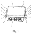
- FIGs. 1 to 6 is an electrical installation box according to a first preferred embodiment of the invention can be seen.
- the electrical installation box has a housing 1 and a lid 2.
- the lid 2 is pressed onto the open side of the housing 1 be, whereby he locked there and firmly connected to the housing 1 is.
- the housing 1 protruding Approaches 3, in each of which a groove 4 is formed.
- To the Lid 2 are respectively corresponding to the groove 4 on two opposite sides spring-like projections 5 formed.
- electrical installation box according to The first preferred embodiment of the invention is on the outside the lid in a corner, a rectangular recess 6 is provided. These Recess 6 is used to label the lid 2 and the attachment of a not shown adhesive labels. Through the recess 6 is the danger Blurring a label reduces or the detachment of a sticker difficult.
- the electrical installation box according to the first preferred Embodiment of the invention as shown in FIGS. 1 to 6, fastening straps 7 on.
- Each of these fastening straps 7 has two eyelets 8 each on, which are designed here as flat slots.
- These eyelets 8 are consecutive arranged, and their direction of execution is parallel to the ground of the housing 1 and parallel to the side wall of the housing 1, at which the Attachment tabs 7 are attached.
- the electrical installation box according to the first preferred embodiment The invention thus secured by means of cable ties 9 on a support 10 by passing the cable ties 9 through the eyelets 8 and around the wearer 10 around and then fixed.
- the electrical installation box according to the first preferred embodiment the invention has in addition to each of their fastening tabs 7 the eyelets 8 each have a bore 11, the longitudinal direction in the normal direction the bottom of the housing 1 extends. This way is a universal one Use of the electrical installation box according to the first preferred embodiment the invention possible, namely both an attachment with Cable ties 9, which are passed through the eyelets 8, as well as a conventional attachment by means of guided through the holes 11 Screws on a wall.
- Figs. 7a and 7b is an electrical installation box according to a second preferred embodiment of the invention can be seen.
- To be infected of the lid 2 to the housing 1 serve here on the one hand a side wall 12 of the Housing 1 and on the other hand, a groove 13 in the lid 2.
- the groove 13 in the lid. 2 is the groove, by means of a placement of the lid 2 on the housing 1 for Close the same takes place.
- To this Way is, as shown in Fig. 7b, readily plugging the lid 2 on the housing 1 so possible that the lid 2, similar to the first preferred embodiment of the invention, laterally adjacent to the housing 1, so that the interior is freely accessible for assembly and Installation work.
- FIG. 8 From Fig. 8 is finally an electrical installation box according to a third preferred embodiment of the invention can be seen.
- the lid 2 a retaining clip 15 which with a Side wall 16 of the lid 2 cooperates, so that the lid 2 on a Side wall 12, namely on a corner 18 of the housing 1, can be plugged.
Abstract
Description
- Fig. 1
- eine elektrische Installationsdose gemäß einem ersten bevorzugten Ausführungsbeispiel der Erfindung in geschlossenem Zustand,
- Fig. 2
- die elektrische Installationsdose gemäß dem ersten bevorzugten Ausführungsbeispiel der Erfindung in geöffnetem Zustand,
- Fig. 3
- die elektrische Installationsdose gemäß dem ersten bevorzugten Ausführungsbeispiel der Erfindung in geöffnetem Zustand mit angestecktem Deckel,
- Fig. 4
- die elektrische Installationsdose gemäß dem ersten bevorzugten Ausführungsbeispiel der Erfindung ebenfalls in geöffnetem Zustand mit angestecktem Deckel in anderer Orientierung,
- Fig. 5
- die elektrische Installationsdose gemäß dem ersten bevorzugten Ausführungsbeispiel der Erfindung, die mit Hilfe eines Schraubenziehers geöffnet wird,
- Fig. 6
- die elektrische Installationsdose gemäß dem ersten bevorzugten Ausführungsbeispiel der Erfindung in einem an einem Träger angebrachten Zustand,
- Fig. 7a, b
- eine elektrische Installationsdose gemäß einem zweiten bevorzugten Ausführungsbeispiel der Erfindung und
- Fig. 8
- eine elektrische Installationsdose gemäß einem dritten bevorzugten Ausführungsbeispiel der Erfindung in einer Ausschnittsvergrößerung.
Claims (17)
- Elektrische Installationsdose, mit einem Gehäuse (1) und einem Deckel (2), wobei der Deckel (2) zum Verschließen des Gehäuses (1) lösbar auf dieses aufsetzbar ist, dadurch gekennzeichnet, daß an dem Deckel (2) oder/und an dem Gehäuse (1) wenigstens ein Befestigungsmittel vorgesehen ist, mit dem der Dekkel (2) an dem Gehäuse (1) derart lösbar befestigbar ist, daß der Innenraum des Gehäuses (1) wenigstens teilweise von außen zugänglich ist.
- Elektrische Installationsdose nach Anspruch 1, dadurch gekennzeichnet, daß der Innenraum des Gehäuses (1) vollständig von außen zugänglich ist.
- Elektrische Installationsdose nach Anspruch 1 oder 2, dadurch gekennzeichnet, daß der Deckel (2) mit dem Befestigungsmittel, vorzugsweise seitlich, an das Gehäuse (1) ansteckbar ist.
- Elektrische Installationsdose nach Anspruch 3, dadurch gekennzeichnet, daß als Befestigungsmittel ein System mit einer Nut (4) und einem in diese Nut (4) eingreifenden federartigen Vorsprung (5) vorgesehen ist.
- Elektrische Installationsdose nach Anspruch 4, dadurch gekennzeichnet, daß die Nut (4) in einem seitlich an dem Deckel (2) oder dem Gehäuse (1) hervorstehenden Ansatz (3) ausgebildet ist und der federartige Vorsprung (5) seitlich an dem Gehäuse (1) bzw. dem Deckel (2) vorgesehen ist.
- Elektrische Installationsdose nach Anspruch 5, dadurch gekennzeichnet, daß bei auf das Gehäuse (1) aufgesetztem Deckel (2) der Ansatz (3) mit der Nut (4) dem federartigen Vorsprung (5) parallel gegenüberliegt und im Abstand von diesem angeordnet ist.
- Elektrische Installationsdose nach Anspruch 3, dadurch gekennzeichnet, daß der dem Boden des Gehäuses (1) abgewandte Bereich einer Seitenwand (12) des Gehäuses (1) mit einer im Deckel (2) vorgesehenen, an ihren Enden (14) offenen Nut (13) zusammenwirkt.
- Elektrische Installationsdose nach Anspruch 7, dadurch gekennzeichnet, daß die Nut (13) am Rand des Deckels (2) vorgesehen ist.
- Elektrische Installationsdose nach einem der Ansprüche 1 bis 3, dadurch gekennzeichnet, daß am Deckel (2) eine Halteklammer (15) vorgesehen ist, die im wesentlichen parallel zu einer Seitenwand (16) des Deckels verläuft, so daß der Deckel (2) mittels der Halteklammer (15) auf eine Seitenwand (12) des Gehäuses (1) aufsteckbar ist.
- Elektrische Installationsdose, mit einem Gehäuse (1) und einem Deckel (2), wobei an dem Gehäuse (1) eine Befestigungslasche (7) vorgesehen ist, insbesondere nach einem der Ansprüche 1 bis 9, dadurch gekennzeichnet, daß die Befestigungslasche (7) eine Öse (8) aufweist, deren Durchführungsrichtung parallel zum Boden des Gehäuses (1) und parallel zu einer Seitenwand (12) des Gehäuses (1) verläuft.
- Elektrische Installationsdose nach Anspruch 10, dadurch gekennzeichnet, daß die Befestigungslasche (7) zwei hintereinander liegende Ösen (8) aufweist, deren Durchführungsrichtung jeweils parallel zum Boden des Gehäuses (1) verläuft.
- Elektrische Installationsdose nach Anspruch 10 oder 11, dadurch gekennzeichnet, daß die Befestigungslasche (7) in Normalenrichtung zum Boden des Gehäuses (1) eine Bohrung (11) aufweist.
- Elektrische Installationsdose nach einem der Ansprüche 10 bis 12, dadurch gekennzeichnet, daß an dem Gehäuse (1) zwei Befestigungslaschen (7) an einander gegenüberliegenden Seiten vorgesehen sind.
- Elektrische Installationsdose, mit einem Gehäuse (1) und einem Deckel (2), insbesondere nach einem der Ansprüche 1 bis 13, dadurch gekennzeichnet, daß auf der Außenseite des Deckels (2) eine vorzugsweise rechteckige Vertiefung (6) vorgesehen ist.
- Elektrische Installationsdose nach Anspruch 14, dadurch gekennzeichnet, daß die Vertiefung (6) eben ist.
- Elektrische Installationsdose nach Anspruch 15, dadurch gekennzeichnet, daß die Vertiefung (6) gegenüber dem Rest des Deckels (2) um 0,5 bis 3 mm, vorzugsweise um 1 mm, abgesenkt ist.
- Elektrische Installationsdose nach einem der Ansprüche 14 bis 16, dadurch gekennzeichnet, daß die Vertiefung (6) in einer Ecke des Deckels (2) vorgesehen ist.
Priority Applications (2)
| Application Number | Priority Date | Filing Date | Title |
|---|---|---|---|
| EP10186146A EP2267856B1 (de) | 2001-11-08 | 2002-08-16 | Elektrische Installationsdose |
| DK10186146.6T DK2267856T3 (da) | 2001-11-08 | 2002-08-16 | Elektrisk installationsboks |
Applications Claiming Priority (4)
| Application Number | Priority Date | Filing Date | Title |
|---|---|---|---|
| DE20118064U | 2001-11-08 | ||
| DE20118064 | 2001-11-08 | ||
| DE20119272U | 2001-11-28 | ||
| DE20119272U DE20119272U1 (de) | 2001-11-28 | 2001-11-28 | Elektrische Installationsdose |
Related Child Applications (2)
| Application Number | Title | Priority Date | Filing Date |
|---|---|---|---|
| EP10186146A Division EP2267856B1 (de) | 2001-11-08 | 2002-08-16 | Elektrische Installationsdose |
| EP10186146.6 Division-Into | 2010-10-01 |
Publications (2)
| Publication Number | Publication Date |
|---|---|
| EP1311042A1 true EP1311042A1 (de) | 2003-05-14 |
| EP1311042B1 EP1311042B1 (de) | 2011-03-23 |
Family
ID=26057273
Family Applications (2)
| Application Number | Title | Priority Date | Filing Date |
|---|---|---|---|
| EP10186146A Expired - Lifetime EP2267856B1 (de) | 2001-11-08 | 2002-08-16 | Elektrische Installationsdose |
| EP02018468A Expired - Lifetime EP1311042B1 (de) | 2001-11-08 | 2002-08-16 | Elektrische Installationsdose |
Family Applications Before (1)
| Application Number | Title | Priority Date | Filing Date |
|---|---|---|---|
| EP10186146A Expired - Lifetime EP2267856B1 (de) | 2001-11-08 | 2002-08-16 | Elektrische Installationsdose |
Country Status (6)
| Country | Link |
|---|---|
| EP (2) | EP2267856B1 (de) |
| AT (1) | ATE503291T1 (de) |
| DE (2) | DE20222000U1 (de) |
| DK (2) | DK2267856T3 (de) |
| ES (1) | ES2397834T3 (de) |
| PL (1) | PL62127Y1 (de) |
Cited By (7)
| Publication number | Priority date | Publication date | Assignee | Title |
|---|---|---|---|---|
| BE1018573A3 (nl) * | 2008-01-28 | 2011-04-05 | Plastic Color Nv | Verbeterde lasdoos. |
| EP2415136A2 (de) * | 2009-03-30 | 2012-02-08 | Phoenix Contact GmbH & Co. KG | Gehäuseanordnung |
| DE202014009976U1 (de) | 2014-12-19 | 2015-02-02 | Axel R. Hidde | Elektrische Abzweig-, Anschluß- und Verteilerdose |
| EP2852266A3 (de) * | 2013-09-23 | 2015-07-15 | Horst Beelenherm | Kabelgehäuse zur Montage an einem Industriesteckverbinder und Anordnung |
| CN112923991A (zh) * | 2021-01-18 | 2021-06-08 | 临沂瑞新水表有限公司 | 一种wph可拆卸式水表外壳 |
| CN112952692A (zh) * | 2021-04-07 | 2021-06-11 | 辽宁工程技术大学 | 一种矿用防爆接线盒端子 |
| CN114884007A (zh) * | 2022-05-09 | 2022-08-09 | 浙江首航实业有限公司 | 一种可分清线路方便检查维修的接头盒 |
Families Citing this family (1)
| Publication number | Priority date | Publication date | Assignee | Title |
|---|---|---|---|---|
| DE202015105676U1 (de) | 2015-10-26 | 2016-10-27 | F-tronic Winfried Fohs Gesellschaft mit beschränkter Haftung | Elektroinstallationsmaterial für die Aufputzmontage |
Citations (3)
| Publication number | Priority date | Publication date | Assignee | Title |
|---|---|---|---|---|
| US4967924A (en) * | 1988-07-01 | 1990-11-06 | Seydel Companies | Cover mounting assembly for electrical junction box |
| DE29616804U1 (de) * | 1996-04-19 | 1997-08-21 | Electro Terminal Gmbh | Kabelverteilerdose |
| EP1058362A1 (de) * | 1999-06-03 | 2000-12-06 | Legrand | Gehäuse für elektrische Geräte mit Verbinder zwischen zwei Elementen |
Family Cites Families (2)
| Publication number | Priority date | Publication date | Assignee | Title |
|---|---|---|---|---|
| US5186661A (en) * | 1992-04-03 | 1993-02-16 | Amp Incorporated | Lid with integral hinges |
| BE1018573A3 (nl) * | 2008-01-28 | 2011-04-05 | Plastic Color Nv | Verbeterde lasdoos. |
-
2002
- 2002-08-16 EP EP10186146A patent/EP2267856B1/de not_active Expired - Lifetime
- 2002-08-16 ES ES10186146T patent/ES2397834T3/es not_active Expired - Lifetime
- 2002-08-16 DE DE20222000U patent/DE20222000U1/de not_active Expired - Lifetime
- 2002-08-16 DE DE50214974T patent/DE50214974D1/de not_active Expired - Lifetime
- 2002-08-16 DK DK10186146.6T patent/DK2267856T3/da active
- 2002-08-16 AT AT02018468T patent/ATE503291T1/de active
- 2002-08-16 DK DK02018468.5T patent/DK1311042T3/da active
- 2002-08-16 EP EP02018468A patent/EP1311042B1/de not_active Expired - Lifetime
- 2002-09-19 PL PL02113537U patent/PL62127Y1/pl unknown
Patent Citations (3)
| Publication number | Priority date | Publication date | Assignee | Title |
|---|---|---|---|---|
| US4967924A (en) * | 1988-07-01 | 1990-11-06 | Seydel Companies | Cover mounting assembly for electrical junction box |
| DE29616804U1 (de) * | 1996-04-19 | 1997-08-21 | Electro Terminal Gmbh | Kabelverteilerdose |
| EP1058362A1 (de) * | 1999-06-03 | 2000-12-06 | Legrand | Gehäuse für elektrische Geräte mit Verbinder zwischen zwei Elementen |
Cited By (7)
| Publication number | Priority date | Publication date | Assignee | Title |
|---|---|---|---|---|
| BE1018573A3 (nl) * | 2008-01-28 | 2011-04-05 | Plastic Color Nv | Verbeterde lasdoos. |
| EP2415136A2 (de) * | 2009-03-30 | 2012-02-08 | Phoenix Contact GmbH & Co. KG | Gehäuseanordnung |
| EP2852266A3 (de) * | 2013-09-23 | 2015-07-15 | Horst Beelenherm | Kabelgehäuse zur Montage an einem Industriesteckverbinder und Anordnung |
| DE202014009976U1 (de) | 2014-12-19 | 2015-02-02 | Axel R. Hidde | Elektrische Abzweig-, Anschluß- und Verteilerdose |
| CN112923991A (zh) * | 2021-01-18 | 2021-06-08 | 临沂瑞新水表有限公司 | 一种wph可拆卸式水表外壳 |
| CN112952692A (zh) * | 2021-04-07 | 2021-06-11 | 辽宁工程技术大学 | 一种矿用防爆接线盒端子 |
| CN114884007A (zh) * | 2022-05-09 | 2022-08-09 | 浙江首航实业有限公司 | 一种可分清线路方便检查维修的接头盒 |
Also Published As
| Publication number | Publication date |
|---|---|
| ATE503291T1 (de) | 2011-04-15 |
| DE20222000U1 (de) | 2010-05-20 |
| DE50214974D1 (de) | 2011-05-05 |
| ES2397834T3 (es) | 2013-03-11 |
| EP1311042B1 (de) | 2011-03-23 |
| PL62127Y1 (pl) | 2006-04-28 |
| PL113537U1 (en) | 2003-05-19 |
| EP2267856A1 (de) | 2010-12-29 |
| DK1311042T3 (da) | 2011-07-25 |
| EP2267856B1 (de) | 2012-10-17 |
| DK2267856T3 (da) | 2013-11-04 |
Similar Documents
| Publication | Publication Date | Title |
|---|---|---|
| EP1659411B1 (de) | Elektronischer Elektrizitätszähler | |
| DE10313989B4 (de) | Kabeldurchführungsvorrichtung | |
| DE102007027861A1 (de) | Montageset für eine Elektrodose | |
| DE3430756C2 (de) | ||
| DE10256463A1 (de) | Elektrisches Verbindergehäuse | |
| EP2267856B1 (de) | Elektrische Installationsdose | |
| DE10320982B4 (de) | Kupplungsstruktur für einen Anschlusskasten und einen Verbindungsblock einer elektrischen Komponente | |
| DE102017104123B3 (de) | Schutztrennvorrichtung für eine Rechtecksteckverbindung | |
| DE102019135726A1 (de) | Halterahmen für einen Steckverbinder | |
| DE102011002135A1 (de) | Steckerelement mit zweiter Kontaktsicherung | |
| DE102006015317B4 (de) | Geräteeinbausatz zur Anordnung eines Gerätes in einer elektrischen Schaltanlage | |
| DE102009022645B4 (de) | Klemmendeckel für einen Elektrizitätszähler und Elektrizitätszähler sowie Verfahren zur Ausrüstung eines Elektrizitätszählers | |
| EP1595318B1 (de) | Kabeldurchführung | |
| DE202009005366U1 (de) | Industrie-Steckvorrichtung | |
| DE102011108925A1 (de) | Montagesystem einer Station, insbesondere Türstation eines Haus-Kommunikationssystems | |
| EP0917276A1 (de) | Statorgehäuse für Elektromotoren | |
| DE1690003C3 (de) | Zerlegbarer Kasten zur Unterbringung elektrischer Geräte | |
| WO2007019816A1 (de) | Kabelbinder | |
| DE102010036707A1 (de) | Elektronisches Gerät mit variabel am Gehäusekorpus befestigbaren Befestigungselementen | |
| DE102008060808A1 (de) | Bodeneinbaukassette für elektrische Installationsgeräte | |
| DE102006059826A1 (de) | Kontaktelement zur Befestigung an einem auf einer Tragschiene aufzurastenden, elektrischen Schaltgerät | |
| WO2014096182A1 (de) | Steckdoseneinsatz | |
| DE202010013994U1 (de) | Quaderförmiges Gehäuse | |
| WO2014114491A2 (de) | Elektrische anschlussdose, insbesondere für einen schaltschrank | |
| DE4230236A1 (de) | Bausatz für Kabelendverschlüsse oder Gehäuse für die elektrische Nachrichtentechnik |
Legal Events
| Date | Code | Title | Description |
|---|---|---|---|
| PUAI | Public reference made under article 153(3) epc to a published international application that has entered the european phase |
Free format text: ORIGINAL CODE: 0009012 |
|
| AK | Designated contracting states |
Designated state(s): AT BE BG CH CY CZ DE DK EE ES FI FR GB GR IE IT LI LU MC NL PT SE SK TR |
|
| AX | Request for extension of the european patent |
Extension state: AL LT LV MK RO SI |
|
| 17P | Request for examination filed |
Effective date: 20030626 |
|
| AKX | Designation fees paid |
Designated state(s): AT BE BG CH CY CZ DE DK EE ES FI FR GB GR IE IT LI LU MC NL PT SE SK TR |
|
| 17Q | First examination report despatched |
Effective date: 20081205 |
|
| GRAP | Despatch of communication of intention to grant a patent |
Free format text: ORIGINAL CODE: EPIDOSNIGR1 |
|
| RIN1 | Information on inventor provided before grant (corrected) |
Inventor name: WERKSHAGEN, BERND Inventor name: SPELSBERG, HOLGER, DIPL.-ING. Inventor name: SCHULTE, HANS Inventor name: SCHMIDT, WIELAND, DIPL.-ING. Inventor name: QUARDT, DIRK, DIPL.-ING. Inventor name: OVERBECK, HANS-DIETER Inventor name: HEINS, PETER |
|
| GRAS | Grant fee paid |
Free format text: ORIGINAL CODE: EPIDOSNIGR3 |
|
| GRAA | (expected) grant |
Free format text: ORIGINAL CODE: 0009210 |
|
| AK | Designated contracting states |
Kind code of ref document: B1 Designated state(s): AT BE BG CH CY CZ DE DK EE ES FI FR GB GR IE IT LI LU MC NL PT SE SK TR |
|
| REG | Reference to a national code |
Ref country code: GB Ref legal event code: FG4D Free format text: NOT ENGLISH |
|
| REG | Reference to a national code |
Ref country code: CH Ref legal event code: EP |
|
| REG | Reference to a national code |
Ref country code: IE Ref legal event code: FG4D |
|
| REF | Corresponds to: |
Ref document number: 50214974 Country of ref document: DE Date of ref document: 20110505 Kind code of ref document: P |
|
| REG | Reference to a national code |
Ref country code: DE Ref legal event code: R096 Ref document number: 50214974 Country of ref document: DE Effective date: 20110505 |
|
| REG | Reference to a national code |
Ref country code: NL Ref legal event code: T3 |
|
| REG | Reference to a national code |
Ref country code: DK Ref legal event code: T3 |
|
| PG25 | Lapsed in a contracting state [announced via postgrant information from national office to epo] |
Ref country code: SE Free format text: LAPSE BECAUSE OF FAILURE TO SUBMIT A TRANSLATION OF THE DESCRIPTION OR TO PAY THE FEE WITHIN THE PRESCRIBED TIME-LIMIT Effective date: 20110323 Ref country code: GR Free format text: LAPSE BECAUSE OF FAILURE TO SUBMIT A TRANSLATION OF THE DESCRIPTION OR TO PAY THE FEE WITHIN THE PRESCRIBED TIME-LIMIT Effective date: 20110624 |
|
| PG25 | Lapsed in a contracting state [announced via postgrant information from national office to epo] |
Ref country code: BG Free format text: LAPSE BECAUSE OF FAILURE TO SUBMIT A TRANSLATION OF THE DESCRIPTION OR TO PAY THE FEE WITHIN THE PRESCRIBED TIME-LIMIT Effective date: 20110623 Ref country code: CY Free format text: LAPSE BECAUSE OF FAILURE TO SUBMIT A TRANSLATION OF THE DESCRIPTION OR TO PAY THE FEE WITHIN THE PRESCRIBED TIME-LIMIT Effective date: 20110323 Ref country code: FI Free format text: LAPSE BECAUSE OF FAILURE TO SUBMIT A TRANSLATION OF THE DESCRIPTION OR TO PAY THE FEE WITHIN THE PRESCRIBED TIME-LIMIT Effective date: 20110323 |
|
| REG | Reference to a national code |
Ref country code: IE Ref legal event code: FD4D |
|
| PG25 | Lapsed in a contracting state [announced via postgrant information from national office to epo] |
Ref country code: PT Free format text: LAPSE BECAUSE OF FAILURE TO SUBMIT A TRANSLATION OF THE DESCRIPTION OR TO PAY THE FEE WITHIN THE PRESCRIBED TIME-LIMIT Effective date: 20110725 Ref country code: EE Free format text: LAPSE BECAUSE OF FAILURE TO SUBMIT A TRANSLATION OF THE DESCRIPTION OR TO PAY THE FEE WITHIN THE PRESCRIBED TIME-LIMIT Effective date: 20110323 |
|
| PG25 | Lapsed in a contracting state [announced via postgrant information from national office to epo] |
Ref country code: SK Free format text: LAPSE BECAUSE OF FAILURE TO SUBMIT A TRANSLATION OF THE DESCRIPTION OR TO PAY THE FEE WITHIN THE PRESCRIBED TIME-LIMIT Effective date: 20110323 Ref country code: ES Free format text: LAPSE BECAUSE OF FAILURE TO SUBMIT A TRANSLATION OF THE DESCRIPTION OR TO PAY THE FEE WITHIN THE PRESCRIBED TIME-LIMIT Effective date: 20110704 |
|
| PLBE | No opposition filed within time limit |
Free format text: ORIGINAL CODE: 0009261 |
|
| STAA | Information on the status of an ep patent application or granted ep patent |
Free format text: STATUS: NO OPPOSITION FILED WITHIN TIME LIMIT |
|
| PG25 | Lapsed in a contracting state [announced via postgrant information from national office to epo] |
Ref country code: IE Free format text: LAPSE BECAUSE OF FAILURE TO SUBMIT A TRANSLATION OF THE DESCRIPTION OR TO PAY THE FEE WITHIN THE PRESCRIBED TIME-LIMIT Effective date: 20110323 |
|
| 26N | No opposition filed |
Effective date: 20111227 |
|
| PG25 | Lapsed in a contracting state [announced via postgrant information from national office to epo] |
Ref country code: MC Free format text: LAPSE BECAUSE OF NON-PAYMENT OF DUE FEES Effective date: 20110831 |
|
| REG | Reference to a national code |
Ref country code: DE Ref legal event code: R097 Ref document number: 50214974 Country of ref document: DE Effective date: 20111227 |
|
| GBPC | Gb: european patent ceased through non-payment of renewal fee |
Effective date: 20110816 |
|
| REG | Reference to a national code |
Ref country code: FR Ref legal event code: ST Effective date: 20120430 |
|
| PG25 | Lapsed in a contracting state [announced via postgrant information from national office to epo] |
Ref country code: IT Free format text: LAPSE BECAUSE OF FAILURE TO SUBMIT A TRANSLATION OF THE DESCRIPTION OR TO PAY THE FEE WITHIN THE PRESCRIBED TIME-LIMIT Effective date: 20110323 |
|
| PG25 | Lapsed in a contracting state [announced via postgrant information from national office to epo] |
Ref country code: GB Free format text: LAPSE BECAUSE OF NON-PAYMENT OF DUE FEES Effective date: 20110816 Ref country code: FR Free format text: LAPSE BECAUSE OF NON-PAYMENT OF DUE FEES Effective date: 20110831 |
|
| PG25 | Lapsed in a contracting state [announced via postgrant information from national office to epo] |
Ref country code: TR Free format text: LAPSE BECAUSE OF FAILURE TO SUBMIT A TRANSLATION OF THE DESCRIPTION OR TO PAY THE FEE WITHIN THE PRESCRIBED TIME-LIMIT Effective date: 20110323 |
|
| PGFP | Annual fee paid to national office [announced via postgrant information from national office to epo] |
Ref country code: LU Payment date: 20180821 Year of fee payment: 17 |
|
| PGFP | Annual fee paid to national office [announced via postgrant information from national office to epo] |
Ref country code: TR Payment date: 20180907 Year of fee payment: 7 |
|
| PG25 | Lapsed in a contracting state [announced via postgrant information from national office to epo] |
Ref country code: LI Free format text: LAPSE BECAUSE OF NON-PAYMENT OF DUE FEES Effective date: 20190831 Ref country code: LU Free format text: LAPSE BECAUSE OF NON-PAYMENT OF DUE FEES Effective date: 20190816 Ref country code: CH Free format text: LAPSE BECAUSE OF NON-PAYMENT OF DUE FEES Effective date: 20190831 |
|
| PGFP | Annual fee paid to national office [announced via postgrant information from national office to epo] |
Ref country code: DK Payment date: 20200821 Year of fee payment: 19 |
|
| PGFP | Annual fee paid to national office [announced via postgrant information from national office to epo] |
Ref country code: NL Payment date: 20210819 Year of fee payment: 20 |
|
| PGFP | Annual fee paid to national office [announced via postgrant information from national office to epo] |
Ref country code: AT Payment date: 20210820 Year of fee payment: 20 Ref country code: CZ Payment date: 20210816 Year of fee payment: 20 |
|
| PGFP | Annual fee paid to national office [announced via postgrant information from national office to epo] |
Ref country code: BE Payment date: 20210819 Year of fee payment: 20 Ref country code: DE Payment date: 20210830 Year of fee payment: 20 |
|
| REG | Reference to a national code |
Ref country code: DK Ref legal event code: EBP Effective date: 20210831 |
|
| PG25 | Lapsed in a contracting state [announced via postgrant information from national office to epo] |
Ref country code: DK Free format text: LAPSE BECAUSE OF NON-PAYMENT OF DUE FEES Effective date: 20210831 |
|
| REG | Reference to a national code |
Ref country code: DE Ref legal event code: R071 Ref document number: 50214974 Country of ref document: DE |
|
| REG | Reference to a national code |
Ref country code: NL Ref legal event code: MK Effective date: 20220815 |
|
| REG | Reference to a national code |
Ref country code: BE Ref legal event code: MK Effective date: 20220816 |
|
| REG | Reference to a national code |
Ref country code: AT Ref legal event code: MK07 Ref document number: 503291 Country of ref document: AT Kind code of ref document: T Effective date: 20220816 |
|
| PG25 | Lapsed in a contracting state [announced via postgrant information from national office to epo] |
Ref country code: CZ Free format text: LAPSE BECAUSE OF EXPIRATION OF PROTECTION Effective date: 20220816 |