EP1311042A1 - Electrical installation box - Google Patents
Electrical installation box Download PDFInfo
- Publication number
- EP1311042A1 EP1311042A1 EP02018468A EP02018468A EP1311042A1 EP 1311042 A1 EP1311042 A1 EP 1311042A1 EP 02018468 A EP02018468 A EP 02018468A EP 02018468 A EP02018468 A EP 02018468A EP 1311042 A1 EP1311042 A1 EP 1311042A1
- Authority
- EP
- European Patent Office
- Prior art keywords
- housing
- installation box
- electrical installation
- lid
- box according
- Prior art date
- Legal status (The legal status is an assumption and is not a legal conclusion. Google has not performed a legal analysis and makes no representation as to the accuracy of the status listed.)
- Granted
Links
Images


Classifications
-
- H—ELECTRICITY
- H02—GENERATION; CONVERSION OR DISTRIBUTION OF ELECTRIC POWER
- H02G—INSTALLATION OF ELECTRIC CABLES OR LINES, OR OF COMBINED OPTICAL AND ELECTRIC CABLES OR LINES
- H02G3/00—Installations of electric cables or lines or protective tubing therefor in or on buildings, equivalent structures or vehicles
- H02G3/02—Details
- H02G3/08—Distribution boxes; Connection or junction boxes
- H02G3/14—Fastening of cover or lid to box
-
- H—ELECTRICITY
- H02—GENERATION; CONVERSION OR DISTRIBUTION OF ELECTRIC POWER
- H02G—INSTALLATION OF ELECTRIC CABLES OR LINES, OR OF COMBINED OPTICAL AND ELECTRIC CABLES OR LINES
- H02G3/00—Installations of electric cables or lines or protective tubing therefor in or on buildings, equivalent structures or vehicles
- H02G3/02—Details
- H02G3/08—Distribution boxes; Connection or junction boxes
- H02G3/081—Bases, casings or covers
Definitions
- the invention relates to an electrical installation box, with a housing and a lid, wherein the lid for closing the housing releasably on this can be placed.
- electrical installation box are such electrical boxes meant to which electrical cables are supplied and / or of which electrical Cables are discharged, with the electrical cables in the electrical Installation box are connected to each other and / or other installations in the electrical installation box are provided. In the simplest case it can in the electrical installation box to a common as a junction box designated can act, which is typically attached to a wall and for the production of circuits z. B. is used for home installation.
- Such electrical installation boxes have a lid for closing of the housing can be placed on this.
- the lid is back from the Housing solvable, thus further access to the in the electrical installation box realized circuit or the installations provided there.
- the lid is releasably secured to the housing thereby that the Cover for closing the housing is pressed onto this and lid and housing by means provided on these Verrast alienen each other lock.
- a Tool such as a screwdriver, required between the lid and housing guided and with the lid is levered off the housing.
- an electrical installation box indicate that it is counteracting a loss of the lid can, without necessarily the lid firmly connected to the housing is.
- the lid and / or on the housing is thus in addition to the closing of the housing with realized the lid at least a second possibility, the lid on the To attach housing, wherein in this second mounting option of Interior of the housing is at least partially accessible from the outside, so that in the interior of the housing assembly and installation work are possible.
- fastening means are provided, with which the lid can be attached to the housing.
- a such attachment of the lid to the housing laterally, d. H. such that the Lid is in the infected state laterally next to the housing.
- d. H. such that the Lid is in the infected state laterally next to the housing.
- plugging itself also done from the side got to.
- fastening means may be provided, with which a plugging takes place from the front.
- a system which has a spring-like projection and a groove associated therewith. This can z. B. the groove in a laterally on the lid or the housing projecting approach, wherein the spring-like projection is provided laterally on the housing or on the lid.
- the fastening means has a double function: on the one hand allows a lateral attachment of the lid to the housing and on the other hand it represents an opening aid.
- the fastening means facing away from the bottom of the housing Serve area of a side wall of the housing, with one on the lid provided, cooperating at their ends groove cooperates.
- the groove is provided at the edge of the lid. Especially is namely in this way such a groove in the lid available, the otherwise for closing the housing with a side wall of the housing cooperates. The fact that the ends of this groove are open, the lid can now also put on the housing so that the cover the interior of the Does not close housing, but laterally protrudes from the housing.
- a retaining clip is, which is substantially parallel to a side wall of the lid.
- the lid can then be plugged onto a side wall of the housing be that the side wall of the housing between the retaining clip and the Side wall of the lid comes to rest.
- the shape of this eyelet can be round, oval or be angular.
- a slot-like eyelet has been proven.
- the together with the electrical installation boxes described above, but also with conventional electrical installation boxes is used on the outside the lid provided a preferably rectangular recess.
- a separate space for a label of the lid is created, wherein the recess is advantageous in that when direct labeling of the Cover the label due to the depression better against blurring is protected.
- the label is made with a separate sticker, so is such a sticker in the region of the recess against mechanical influences, which could lead to a detachment of the sticker, better protected.
- the recess is flat, d. H. their surface runs parallel to the rest Surface of the lid.
- Such a flat depression is particularly easy label or with a sticker.
- Lowering the depression relative to the remainder of the lid is preferably between 0.5 and 3 mm. Very particular preference is a reduction of about 1 mm.
- the recess is provided in a corner of the lid. Is such a cover in which the recess is provided in a corner, arranged such that the recess is in the upper left corner, so labeling is for one Right-handed relieved, as they put his hand in the remaining area can. For left-handers applies accordingly.
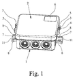
- FIGs. 1 to 6 is an electrical installation box according to a first preferred embodiment of the invention can be seen.
- the electrical installation box has a housing 1 and a lid 2.
- the lid 2 is pressed onto the open side of the housing 1 be, whereby he locked there and firmly connected to the housing 1 is.
- the housing 1 protruding Approaches 3, in each of which a groove 4 is formed.
- To the Lid 2 are respectively corresponding to the groove 4 on two opposite sides spring-like projections 5 formed.
- electrical installation box according to The first preferred embodiment of the invention is on the outside the lid in a corner, a rectangular recess 6 is provided. These Recess 6 is used to label the lid 2 and the attachment of a not shown adhesive labels. Through the recess 6 is the danger Blurring a label reduces or the detachment of a sticker difficult.
- the electrical installation box according to the first preferred Embodiment of the invention as shown in FIGS. 1 to 6, fastening straps 7 on.
- Each of these fastening straps 7 has two eyelets 8 each on, which are designed here as flat slots.
- These eyelets 8 are consecutive arranged, and their direction of execution is parallel to the ground of the housing 1 and parallel to the side wall of the housing 1, at which the Attachment tabs 7 are attached.
- the electrical installation box according to the first preferred embodiment The invention thus secured by means of cable ties 9 on a support 10 by passing the cable ties 9 through the eyelets 8 and around the wearer 10 around and then fixed.
- the electrical installation box according to the first preferred embodiment the invention has in addition to each of their fastening tabs 7 the eyelets 8 each have a bore 11, the longitudinal direction in the normal direction the bottom of the housing 1 extends. This way is a universal one Use of the electrical installation box according to the first preferred embodiment the invention possible, namely both an attachment with Cable ties 9, which are passed through the eyelets 8, as well as a conventional attachment by means of guided through the holes 11 Screws on a wall.
- Figs. 7a and 7b is an electrical installation box according to a second preferred embodiment of the invention can be seen.
- To be infected of the lid 2 to the housing 1 serve here on the one hand a side wall 12 of the Housing 1 and on the other hand, a groove 13 in the lid 2.
- the groove 13 in the lid. 2 is the groove, by means of a placement of the lid 2 on the housing 1 for Close the same takes place.
- To this Way is, as shown in Fig. 7b, readily plugging the lid 2 on the housing 1 so possible that the lid 2, similar to the first preferred embodiment of the invention, laterally adjacent to the housing 1, so that the interior is freely accessible for assembly and Installation work.
- FIG. 8 From Fig. 8 is finally an electrical installation box according to a third preferred embodiment of the invention can be seen.
- the lid 2 a retaining clip 15 which with a Side wall 16 of the lid 2 cooperates, so that the lid 2 on a Side wall 12, namely on a corner 18 of the housing 1, can be plugged.
Landscapes
- Engineering & Computer Science (AREA)
- Architecture (AREA)
- Civil Engineering (AREA)
- Structural Engineering (AREA)
- Casings For Electric Apparatus (AREA)
- Connection Or Junction Boxes (AREA)
- Dry Shavers And Clippers (AREA)
- Connector Housings Or Holding Contact Members (AREA)
Abstract
Description
Die Erfindung betrifft eine elektrische Installationsdose, mit einem Gehäuse und einem Deckel, wobei der Deckel zum Verschließen des Gehäuses lösbar auf dieses aufsetzbar ist.The invention relates to an electrical installation box, with a housing and a lid, wherein the lid for closing the housing releasably on this can be placed.
Mit dem Begriff "elektrische Installationsdose" sind solche elektrischen Dosen gemeint, denen elektrische Kabel zugeführt werden und/oder von denen elektrische Kabel abgeführt werden, wobei die elektrischen Kabel in der elektrischen Installationsdose miteinander verbunden sind und/oder weitere Installationen in der elektrischen Installationsdose vorgesehen sind. Im einfachsten Fall kann es sich bei der elektrischen Installationsdose um eine gemeinhin als Verbindungsdose bezeichnete Dose handeln, die typischerweise an einer Wand befestigt wird und zur Herstellung von Schaltungen z. B. für die Hausinstallation dient.By the term "electrical installation box" are such electrical boxes meant to which electrical cables are supplied and / or of which electrical Cables are discharged, with the electrical cables in the electrical Installation box are connected to each other and / or other installations in the electrical installation box are provided. In the simplest case it can in the electrical installation box to a common as a junction box designated can act, which is typically attached to a wall and for the production of circuits z. B. is used for home installation.
Solche elektrischen Installationsdosen weisen einen Deckel auf, der zum Verschließen des Gehäuses auf dieses aufsetzbar ist. Der Deckel ist wieder von dem Gehäuse lösbar, um somit weiterhin Zugang zu der in der elektrischen Installationsdose realisierten Schaltung bzw. den dort vorgesehenen Installationen zu erhalten. Häufig ist der Deckel an dem Gehäuse dadurch lösbar befestigt, daß der Deckel zum Verschließen des Gehäuses auf dieses aufgedrückt wird und Deckel und Gehäuse mittels an diesen vorgesehenen Verrasteinrichtungen miteinander verrasten. Zum Lösen des Deckels von dem Gehäuse ist dann typischerweise ein Werkzeug, wie ein Schraubenzieher, erforderlich, das zwischen Deckel und Gehäuse geführt und mit dem der Deckel von dem Gehäuse abgehebelt wird.Such electrical installation boxes have a lid for closing of the housing can be placed on this. The lid is back from the Housing solvable, thus further access to the in the electrical installation box realized circuit or the installations provided there. Often, the lid is releasably secured to the housing thereby that the Cover for closing the housing is pressed onto this and lid and housing by means provided on these Verrasteinrichtungen each other lock. To release the lid from the housing is then typically a Tool, such as a screwdriver, required between the lid and housing guided and with the lid is levered off the housing.
Bei der Anbringung und Bestückung einer elektrischen Installationsdose wird im allgemeinen so vorgegangen, daß die elektrische Installationsdose zuerst an der Wand angebracht wird und danach mit Kabeln und gegebenenfalls weiteren Installationen versehen wird. Sowohl beim Anbringen der elektrischen Installationsdose an die Wand als auch beim Installieren der Kabel usw. darf das Gehäuse nicht mit dem Deckel verschlossen sein, da ansonsten der Innenraum des Gehäuses zur Installation nicht zugänglich wäre. Der Deckel muß also von dem Gehäuse entfernt und an einem anderen Platz aufbewahrt werden, bis die Montage und Installation der elektrischen Installationsdose beendet ist und das Gehäuse wieder mit dem Deckel verschlossen werden soll. Dabei besteht die Gefahr, daß der Deckel verlorengeht.When attaching and equipping an electrical installation box is in General procedure so that the electrical installation box first at the Wall is attached and then with cables and possibly other installations is provided. Both when attaching the electrical installation box to the wall as well as when installing the cables, etc. may the housing not be closed with the lid, otherwise the interior of the housing would not be accessible for installation. The lid must therefore from the housing be removed and stored in another place until the assembly and Installation of the electrical installation box is finished and the housing again to be closed with the lid. There is a risk that the Lid is lost.
Dieser Gefahr, daß der Deckel verlorengeht, ist bisher z. B. dadurch begegnet worden, daß der Deckel mit dem Gehäuse mittels eines flexiblen Bändchens fest verbunden ist. Auf diese Weise kann der Deckel zumindest nicht ohne weiteres von dem Gehäuse entfernt werden, so daß ein Verlieren des Deckels praktisch ausgeschlossen ist. Jedoch ergibt sich bei dieser Lösung ein Problem dadurch, daß der Deckel immer am Gehäuse verbleiben muß, so daß z. B. auch ein Beschriften des Deckels in diesem Zustand erfolgen muß. Ein Beschriften z. B. an einem separaten Platz und/oder mit einer separaten Einrichtung ist dann nicht mehr möglich.This danger that the lid is lost, so far z. B. thereby encountered been that the lid to the housing by means of a flexible ribbon firmly connected is. In this way, the lid at least not readily be removed from the housing, so that a loss of the lid practical is excluded. However, this solution poses a problem in that that the lid must always remain on the housing so that z. B. also a label the lid must be in this state. A labeling z. B. on a separate place and / or with a separate facility is not more is possible.
Dementsprechend ist es die Aufgabe der Erfindung, eine elektrische Installationsdose anzugeben, bei der einem Verlieren des Deckels entgegengewirkt werden kann, ohne daß der Deckel zwangsläufig fest mit dem Gehäuse verbunden ist.Accordingly, it is the object of the invention, an electrical installation box indicate that it is counteracting a loss of the lid can, without necessarily the lid firmly connected to the housing is.
Ausgehend von der eingangs beschriebenen elektrischen Installationsdose ist die zuvor hergeleitete und aufgezeigte Aufgabe dadurch gelöst, daß an dem Deckel oder/und an dem Gehäuse wenigstens ein Befestigungsmittel vorgesehen ist, mit dem der Deckel an dem Gehäuse derart lösbar befestigbar ist, daß der Innenraum des Gehäuse wenigstens teilweise von außen zugänglich ist.Starting from the electrical installation box described above is the previously derived and indicated object achieved in that on the lid or / and on the housing at least one fastening means is provided, with the lid on the housing is releasably fastened such that the interior the housing is at least partially accessible from the outside.
Durch das erfindungsgemäß vorgesehene Befestigungsmittel an dem Deckel oder/und an dem Gehäuse wird also neben dem Verschließen des Gehäuses mit dem Deckel wenigstens eine zweite Möglichkeit realisiert, den Deckel an dem Gehäuse zu befestigen, wobei bei dieser zweiten Befestigungsmöglichkeit der Innenraum des Gehäuses wenigstens teilweise von außen zugänglich ist, so daß im Innenraum des Gehäuses Montage- und Installationsarbeiten möglich sind.By the inventively provided fastener on the lid and / or on the housing is thus in addition to the closing of the housing with realized the lid at least a second possibility, the lid on the To attach housing, wherein in this second mounting option of Interior of the housing is at least partially accessible from the outside, so that in the interior of the housing assembly and installation work are possible.
Grundsätzlich ist es dabei nicht erforderlich, daß der gesamte Innenraum der elektrischen Installationsdose zugänglich ist, sofern zumindest der Innenraum des Gehäuses erreicht werden kann, der für die Montage- und Installationsarbeiten erforderlich ist. Gemäß einer bevorzugten Weiterbildung der Erfindung ist jedoch vorgesehen, daß der Innenraum des Gehäuses vollständig von außen zugänglich ist. Auf diese Weise wird nämlich eine universelle Einsetzbarkeit der elektrischen Installationsdose gewährleistet.Basically, it is not necessary that the entire interior of the electrical installation box is accessible, provided at least the interior of the housing can be achieved, for the assembly and installation work is required. According to a preferred embodiment of the invention However, provided that the interior of the housing completely accessible from the outside is. In this way, namely, a universal applicability of ensured electrical installation box.
Grundsätzlich sind eine Vielzahl von Befestigungsmitteln denkbar, mit denen der Deckel an dem Gehäuse lösbar befestigt werden kann. Gemäß einer bevorzugten Weiterbildung der Erfindung sind jedoch solche Befestigungsmittel vorgesehen, mit denen der Deckel an das Gehäuse ansteckbar ist. Vorzugsweise erfolgt ein solches Anstecken des Deckels an das Gehäuse seitlich, d. h. derart, daß sich der Deckel in angestecktem Zustand seitlich neben dem Gehäuse befindet. Dies bedeutet nicht zwangläufig, daß das Anstecken selbst auch von der Seite her erfolgen muß. Es können nämlich auch solche Befestigungsmittel vorgesehen sein, mit denen ein Anstecken von vorne erfolgt.Basically, a variety of fasteners are conceivable with which the Lid can be releasably attached to the housing. According to a preferred Development of the invention, however, such fastening means are provided, with which the lid can be attached to the housing. Preferably, a such attachment of the lid to the housing laterally, d. H. such that the Lid is in the infected state laterally next to the housing. this means not necessarily that the plugging itself also done from the side got to. Namely, such fastening means may be provided, with which a plugging takes place from the front.
Bezüglich der Befestigungsmittel, mit denen ein Anstecken des Deckels an das Gehäuse erfolgen kann, ist eine Vielzahl von Variationen denkbar. Gemäß einer bevorzugten Weiterbildung der Erfindung ist jedoch vorgesehen, daß zum Anstecken des Deckels an das Gehäuse als Befestigungsmittel ein System vorgesehen ist, das einen federartigen Vorsprung und eine diesem zugeordnete Nut aufweist. Dazu kann z. B. die Nut in einem seitlich an dem Deckel oder dem Gehäuse hervorstehenden Ansatz ausgebildet sein, wobei der federartige Vorsprung seitlich an dem Gehäuse bzw. an dem Deckel vorgesehen ist.Regarding the fastening means with which a plugging of the lid to the Housing can be done, a variety of variations is conceivable. According to one preferred embodiment of the invention, however, is provided that for plugging the cover to the housing as a fastening means provided a system is, which has a spring-like projection and a groove associated therewith. This can z. B. the groove in a laterally on the lid or the housing projecting approach, wherein the spring-like projection is provided laterally on the housing or on the lid.
Diese Ausführungsform ist insbesondere dann besonders vorteilhaft, wenn die Nut und der federartige Vorsprung derart angeordnet sind, daß bei auf das Gehäuse aufgesetztem Deckel der Ansatz mit der Nut dem federartigen Vorsprung parallel gegenüberliegt und im Abstand von diesem angeordnet ist. Dann werden nämlich durch den Ansatz mit der Nut einerseits und dem federartigen Vorsprung andererseits Ansatzflächen für ein Werkzeug, wie einen Schraubenzieher, zum Ablösen des Deckels von dem Gehäuse bereitgestellt. Durch diese Anordnung muß der Schraubenzieher also nicht mehr auf schwierige Weise und teilweise unter Verletzung des Deckels und des Gehäuses in einen geringen Zwischenraum zwischen Deckel und Gehäuse eingebracht werden, sondern es wird eine eigens dafür vorgesehene Öffnungshilfe bereitgestellt, mit Hilfe derer der Deckel auf einfache Weise von dem Gehäuse gelöst werden kann, ohne daß Deckel oder Gehäuse beschädigt werden. Bei dieser bevorzugten Weiterbildung der Erfindung weist das Befestigungsmittel also eine Doppelfunktion auf: Einerseits ermöglicht es ein seitliches Anstecken des Deckels an das Gehäuse und andererseits stellt es eine Öffnungshilfe dar.This embodiment is especially advantageous when the Groove and the spring-like projection are arranged such that when on the housing attached cover the approach with the groove the spring-like projection is parallel opposite and arranged at a distance from this. Then be namely by the approach with the groove on the one hand and the spring-like projection other hand, attachment surfaces for a tool, such as a screwdriver, for detaching the lid from the housing. By this arrangement So the screwdriver does not have to be difficult and partial in violation of the cover and the housing in a small gap be inserted between the lid and housing, but it will a specially provided opening aid provided by means of which the Can be easily detached from the housing cover without Cover or housing may be damaged. In this preferred embodiment Thus, according to the invention, the fastening means has a double function: on the one hand allows a lateral attachment of the lid to the housing and on the other hand it represents an opening aid.
Alternativ dazu kann als Befestigungsmittel der dem Boden des Gehäuses abgewandte Bereich einer Seitenwand des Gehäuses dienen, der mit einer am Deckel vorgesehenen, an ihren Enden offenen Nut zusammenwirkt. Dabei ist es besonders bevorzugt, daß die Nut am Rand des Deckels vorgesehen ist. Insbesondere ist nämlich auf diese Weise eine solche Nut im Deckel nutzbar, die ansonsten zum Verschließen des Gehäuses mit einer Seitenwand des Gehäuses zusammenwirkt. Dadurch, daß die Enden dieser Nut offen sind, läßt sich der Deckel nunmehr auch derart auf das Gehäuse aufstecken, daß der Deckel den Innenraum des Gehäuses nicht verschließt, sondern seitlich von dem Gehäuse wegsteht.Alternatively, as the fastening means facing away from the bottom of the housing Serve area of a side wall of the housing, with one on the lid provided, cooperating at their ends groove cooperates. It is special preferred that the groove is provided at the edge of the lid. Especially is namely in this way such a groove in the lid available, the otherwise for closing the housing with a side wall of the housing cooperates. The fact that the ends of this groove are open, the lid can now also put on the housing so that the cover the interior of the Does not close housing, but laterally protrudes from the housing.
Schließlich ist gemäß einer weiteren bevorzugten Weiterbildung der Erfindung vorgesehen, daß als Befestigungsmittel am Deckel eine Halteklammer vorgesehen ist, die im wesentlichen parallel zu einer Seitenwand des Deckels verläuft. Der Deckel kann dann derart auf eine Seitenwand des Gehäuses aufgesteckt werden, daß die Seitenwand des Gehäuses zwischen der Halteklammer und der Seitenwand des Deckels zu liegen kommt. Diese Lösung ist besonders einfach, da lediglich am Deckel ein Befestigungsmittel, nämlich die Halteklammer, vorgesehen werden muß und ansonsten der obere Bereich der ohnehin schon vorhandenen Seitenwand des Gehäuses verwendet werden kann.Finally, according to another preferred embodiment of the invention provided that provided as a fastening means on the lid, a retaining clip is, which is substantially parallel to a side wall of the lid. The lid can then be plugged onto a side wall of the housing be that the side wall of the housing between the retaining clip and the Side wall of the lid comes to rest. This solution is especially easy because only on the lid, a fastening means, namely the retaining clip provided must be and otherwise the upper part of the already existing Sidewall of the housing can be used.
Eine besonders bevorzugte Weiterbildung der zuvor beschriebenen elektrischen Installationsdose, die jedoch auch mit anderen herkömmlichen elektrischen Installationsdosen verwirklichbar ist, besteht darin, daß an dem Gehäuse eine Befestigungslasche vorgesehen ist, wobei die Befestigungslasche eine Öse aufweist, deren Durchführungsrichtung parallel zum Boden des Gehäuses und parallel zu einer Seitenwand des Gehäuses verläuft. Die Form dieser Öse kann rund, oval oder eckig sein. Insbesondere hat sich eine schlitzartige Öse bewährt.A particularly preferred development of the electrical described above Installation box, but also with other conventional electrical installation boxes is realizable, is that on the housing a fastening tab is provided, wherein the fastening tab has an eyelet, the implementation direction parallel to the bottom of the housing and parallel to a side wall of the housing extends. The shape of this eyelet can be round, oval or be angular. In particular, a slot-like eyelet has been proven.
Allgemein bekannt ist es, daß an dem Gehäuse Befestigungslaschen mit Bohrungen in Normalenrichtung des Bodens des Gehäuses vorgesehen sind. Mittels dieser Bohrungen läßt sich das Gehäuse z. B. mit Hilfe von Schrauben an einer Wand befestigen, so daß der Boden des Gehäuses an der Wand anliegt. Teilweise ist es jedoch erforderlich, daß das Gehäuse nicht an einer Wand, sondern an einem Träger oder einem Rohr befestigt werden muß, wobei an dem Träger bzw. dem Rohr keine Befestigung mittels Schrauben möglich ist. In einem solchen Fall ist durch die zuvor beschriebene elektrische Installationsdose, die Befestigungslaschen mit einer Öse aufweist, deren Durchführungsrichtung parallel zum Boden des Gehäuses und parallel zu einer Seitenwand des Gehäuses verläuft, auf einfache Weise möglich, das Gehäuse mittels einer Bindetechnik, z. B. mit Hilfe von Kabelbindern, an dem Träger bzw. dem Rohr zu befestigen. Dadurch, daß die Durchführungsrichtung der Öse parallel zum Boden des Gehäuses und parallel zur Seitenwand des Gehäuses verläuft, kommt es zu keinen Verknickungen eines durch die Öse hindurchgeführten Kabelbinders, wie dies der Fall wäre, wenn der Kabelbinder durch eine aus dem Stand der Technik bekannte Bohrung geführt werden würde, deren Durchführungsrichtung der Normalenrichtung des Bodens des Gehäuses entspricht.It is generally known that on the housing mounting tabs with holes are provided in the normal direction of the bottom of the housing. By means of this Holes can be the case z. B. by means of screws on one Fasten the wall so that the bottom of the housing rests against the wall. Partially However, it is necessary that the housing not on a wall, but on a Carrier or a pipe must be attached, wherein on the carrier or the pipe no fastening by means of screws is possible. In such a Case is through the electrical installation box described above, the attachment tabs having an eyelet, the implementation direction parallel to Bottom of the housing and parallel to a side wall of the housing runs on simple way possible, the housing by means of a binding technique, for. B. with the help cable ties to be attached to the support or the pipe. As a result of that the direction of execution of the eyelet parallel to the bottom of the housing and parallel to the side wall of the housing, there is no kinking a cable tie passed through the eyelet, as would be the case, when the cable tie by a known from the prior art hole would be performed, the direction of execution of the normal direction of the Floor of the housing corresponds.
Es ist möglich, solche elektrischen Installationsdosen bereitzustellen, bei denen die Befestigungslasche lediglich die in Rede stehende Öse aufweist. Gemäß einer bevorzugten Weiterbildung der Erfindung ist jedoch vorgesehen, daß zusätzlich zu der Öse die Befestigungslasche eine schon aus dem Stand der Technik bekannte Bohrung aufweist, die in Normalenrichtung zum Boden des Gehäuses verläuft. Auf diese Weise ist ein universeller Einsatz der elektrischen Installationsdose möglich: Die elektrische Installationsdose kann nämlich auf diese Weise sowohl an eine Wand angeschraubt als auch an einem Träger oder einem Rohr mittels einer Bindetechnik befestigt werden.It is possible to provide such electrical installation boxes in which the fastening tab has only the eyelet in question. According to one preferred embodiment of the invention, however, is provided that in addition to the eyelet the fastening strap already known from the prior art Has bore in the normal direction to the bottom of the housing runs. This is a universal use of the electrical installation box possible: The electrical installation box can namely on this Both screwed to a wall as well as on a carrier or a Pipe are attached by means of a binding technique.
Grundsätzlich ist das Vorsehen von lediglich einer Befestigungslasche mit lediglich einer Öse ausreichend. Eine stabilere Befestigung der elektrischen Installationsdose läßt sich jedoch dadurch realisieren, daß gemäß einer bevorzugten Weiterbildung der Erfindung vorgesehen ist, daß an dem Gehäuse zwei Befestigungslaschen an einander gegenüberliegenden Seiten vorgesehen sind, die vorzugsweise jeweils zwei Ösen aufweisen. Dabei sind die Ösen einer jeden Befestigungslasche vorzugsweise hintereinander angeordnet.Basically, the provision of only one mounting strap with only a loop enough. A more stable attachment of the electrical installation box However, can be realized in that according to a preferred Further development of the invention is provided that on the housing two fastening tabs are provided on opposite sides, preferably each have two eyelets. The eyelets of each fastening strap are preferably arranged one behind the other.
Gemäß einer weiteren bevorzugten Weiterbildung der Erfindung, die zusammen mit den zuvor beschriebenen elektrischen Installationsdosen, jedoch auch mit herkömmlichen elektrischen Installationsdosen verwendbar ist, ist auf der Außenseite des Deckels eine vorzugsweise rechteckige Vertiefung vorgesehen. Dadurch wird ein eigener Platz für eine Beschriftung des Deckels geschaffen, wobei die Vertiefung insofern vorteilhaft ist, als daß bei einer direkten Beschriftung des Deckels die Beschriftung aufgrund der Vertiefung besser gegen ein Verwischen geschützt ist. Erfolgt die Beschriftung mit einem separaten Aufkleber, so ist auch ein solcher Aufkleber im Bereich der Vertiefung gegen mechanische Einflüsse, die zu einem Ablösen des Aufklebers führen könnten, besser geschützt.According to another preferred embodiment of the invention, the together with the electrical installation boxes described above, but also with conventional electrical installation boxes is used on the outside the lid provided a preferably rectangular recess. Thereby a separate space for a label of the lid is created, wherein the recess is advantageous in that when direct labeling of the Cover the label due to the depression better against blurring is protected. If the label is made with a separate sticker, so is such a sticker in the region of the recess against mechanical influences, which could lead to a detachment of the sticker, better protected.
Vorzugsweise ist die Vertiefung eben, d. h. ihre Fläche verläuft parallel zur restlichen Fläche des Deckels. Eine solche ebene Vertiefung läßt sich besonders einfach beschriften bzw. mit einem Aufkleber versehen. Die Absenkung der Vertiefung gegenüber dem Rest des Deckels liegt vorzugsweise zwischen 0,5 und 3 mm. Ganz besonders bevorzugt ist eine Absenkung um ca. 1 mm. Schließlich ist gemäß einer bevorzugten Weiterbildung der Erfindung vorgesehen, daß die Vertiefung in eine Ecke des Deckels vorgesehen ist. Ist ein solcher Deckel, bei der die Vertiefung in eine Ecke vorgesehen ist, derart angeordnet, daß sich die Vertiefung in der linken oberen Ecke befindet, so ist das Beschriften für einen Rechtshänder erleichtert, da dieser seine Hand im verbleibenden Bereich ablegen kann. Für Linkshänder gilt entsprechendes.Preferably, the recess is flat, d. H. their surface runs parallel to the rest Surface of the lid. Such a flat depression is particularly easy label or with a sticker. Lowering the depression relative to the remainder of the lid is preferably between 0.5 and 3 mm. Very particular preference is a reduction of about 1 mm. Finally is provided according to a preferred embodiment of the invention that the recess is provided in a corner of the lid. Is such a cover in which the recess is provided in a corner, arranged such that the recess is in the upper left corner, so labeling is for one Right-handed relieved, as they put his hand in the remaining area can. For left-handers applies accordingly.
Im einzelnen gibt es nun eine Vielzahl von Möglichkeiten, die elektrische Installationsdose auszugestalten und weiterzubilden. Dazu wird auf die Unteransprüche sowie die nachfolgende detaillierte Beschreibung bevorzugter Ausführungsbeispiele der Erfindung unter Bezugnahme auf die Zeichnungen verwiesen.In particular, there are now a variety of ways, the electrical installation box to design and develop. For this, the dependent claims as well as the following detailed description of preferred embodiments of the invention with reference to the drawings.
In der Zeichnung zeigt
- Fig. 1
- eine elektrische Installationsdose gemäß einem ersten bevorzugten Ausführungsbeispiel der Erfindung in geschlossenem Zustand,
- Fig. 2
- die elektrische Installationsdose gemäß dem ersten bevorzugten Ausführungsbeispiel der Erfindung in geöffnetem Zustand,
- Fig. 3
- die elektrische Installationsdose gemäß dem ersten bevorzugten Ausführungsbeispiel der Erfindung in geöffnetem Zustand mit angestecktem Deckel,
- Fig. 4
- die elektrische Installationsdose gemäß dem ersten bevorzugten Ausführungsbeispiel der Erfindung ebenfalls in geöffnetem Zustand mit angestecktem Deckel in anderer Orientierung,
- Fig. 5
- die elektrische Installationsdose gemäß dem ersten bevorzugten Ausführungsbeispiel der Erfindung, die mit Hilfe eines Schraubenziehers geöffnet wird,
- Fig. 6
- die elektrische Installationsdose gemäß dem ersten bevorzugten Ausführungsbeispiel der Erfindung in einem an einem Träger angebrachten Zustand,
- Fig. 7a, b
- eine elektrische Installationsdose gemäß einem zweiten bevorzugten Ausführungsbeispiel der Erfindung und
- Fig. 8
- eine elektrische Installationsdose gemäß einem dritten bevorzugten Ausführungsbeispiel der Erfindung in einer Ausschnittsvergrößerung.
- Fig. 1
- an electrical installation box according to a first preferred embodiment of the invention in the closed state,
- Fig. 2
- the electrical installation box according to the first preferred embodiment of the invention in the open state,
- Fig. 3
- the electrical installation box according to the first preferred embodiment of the invention in the open state with plugged lid,
- Fig. 4
- the electrical installation box according to the first preferred embodiment of the invention also in the open state with plugged lid in a different orientation,
- Fig. 5
- the electrical installation box according to the first preferred embodiment of the invention, which is opened by means of a screwdriver,
- Fig. 6
- the electrical installation box according to the first preferred embodiment of the invention in a state attached to a carrier,
- Fig. 7a, b
- an electrical installation box according to a second preferred embodiment of the invention and
- Fig. 8
- an electrical installation box according to a third preferred embodiment of the invention in an enlarged detail.
Aus den Fig. 1 bis 6 ist eine elektrische Installationsdose gemäß einem ersten
bevorzugten Ausführungsbeispiel der Erfindung ersichtlich. Die elektrische Installationsdose
weist ein Gehäuse 1 sowie einen Deckel 2 auf. Zum Verschließen
des Gehäuses 1 kann der Deckel 2 auf die offene Seite des Gehäuses 1 aufgedrückt
werden, wodurch er dort verrastet und fest mit dem Gehäuse 1 verbunden
ist. Auf zwei einander gegenüberliegenden Seiten weist das Gehäuse 1 hervorstehende
Ansätze 3 auf, in denen jeweils eine Nut 4 ausgebildet ist. An dem
Deckel 2 sind an zwei einander gegenüberliegenden Seiten jeweils der Nut 4 entsprechende
federartige Vorsprünge 5 ausgebildet.From Figs. 1 to 6 is an electrical installation box according to a first
preferred embodiment of the invention can be seen. The electrical installation box
has a
Bei abgenommenen Deckel 2 kann dieser durch Einstecken eines federartigen
Vorsprungs 5 in eine Nut 4 an dem Gehäuse 1 befestigt werden. Dabei ist es, wie
aus den Fig. 3 und 4 ersichtlich, möglich, den Deckel 2 mit seiner Außenseite
nach vorne oder nach hinten einzustecken.When removed
In dem Zustand, in dem der Deckel 2 seitlich an das Gehäuse 1 angesteckt ist, ist
der Innenraum des Gehäuses 1 frei zugänglich, so daß die erforderlichen Montage-
und Installationsarbeiten durchgeführt werden können. Der Deckel 2 stört
dabei nicht, kann jedoch auch nicht verlorengehen. Nach Beendigung der Montage-
und Installationsarbeiten wird der Deckel 2 einfach auf das Gehäuse 1 aufgedrückt
und mit diesem verrastet. Wie aus Fig. 5 ersichtlich, ist danach ein Ablösen
des Deckels 2 von dem Gehäuse 1 auf einfache Weise dadurch möglich,
daß die jeweils eine Nut 4 aufweisenden Ansätze 3 bei mit dem Deckel 2 verschlossenem
Gehäuse 1 parallel und im Abstand zu den federartigen Vorsprüngen
5 zu liegen kommen, so daß mit Hilfe z. B. eines Schraubenziehers 19 der
Deckel 2 von dem Gehäuse 1 auf einfache Weise durch Abhebeln gelöst werden
kann.In the state in which the
Bei der in den Fig. 1 bis 6 dargestellten elektrischen Installationsdose gemäß
dem ersten bevorzugten Ausführungsbeispiel der Erfindung ist auf der Außenseite
des Deckels in einer Ecke eine rechteckige Vertiefung 6 vorgesehen. Diese
Vertiefung 6 dient der Beschriftung des Deckels 2 bzw. der Anbringung eines
nicht weiter dargestellten Klebeetiketts. Durch die Vertiefung 6 wird die Gefahr
eines Verwischens einer Beschriftung vermindert bzw. das Ablösen eines Klebeetiketts
erschwert.In the illustrated in FIGS. 1 to 6 electrical installation box according to
The first preferred embodiment of the invention is on the outside
the lid in a corner, a
Ferner weist die elektrische Installationsdose gemäß dem ersten bevorzugten
Ausführungsbeispiel der Erfindung, wie aus Fig. 1 bis 6 ersichtlich, Befestigungslaschen
7 auf. Jede dieser Befestigungslaschen 7 weist jeweils zwei Ösen 8
auf, die vorliegend als flache Schlitze ausgebildet sind. Diese Ösen 8 sind hintereinander
angeordnet, und ihre Durchführungsrichtung verläuft parallel zum Boden
des Gehäuses 1 und parallel zu der Seitenwand des Gehäuses 1, an der die
Befestigungslaschen 7 angebracht sind. Wie aus Fig. 6 ersichtlich, kann die
elektrische Installationsdose gemäß dem ersten bevorzugten Ausführungsbeispiel
der Erfindung somit mit Hilfe von Kabelbindern 9 an einem Träger 10 befestigt
werden, indem die Kabelbinder 9 durch die Ösen 8 hindurch und um den Träger
10 herum geführt und danach fixiert werden.Furthermore, the electrical installation box according to the first preferred
Embodiment of the invention, as shown in FIGS. 1 to 6, fastening straps
7 on. Each of these
Die elektrische Installationsdose gemäß dem ersten bevorzugten Ausführungsbeispiel
der Erfindung weist an jeder ihrer Befestigungslaschen 7 zusätzlich zu
den Ösen 8 jeweils eine Bohrung 11 auf, deren Längsrichtung in Normalenrichtung
des Bodens des Gehäuses 1 verläuft. Auf diese Weise ist ein universeller
Einsatz der elektrischen Installationsdose gemäß dem ersten bevorzugten Ausführungsbeispiel
der Erfindung möglich, nämlich sowohl eine Anbringung mit
Kabelbindern 9, die durch die Ösen 8 hindurch geführt werden, als auch eine
herkömmliche Befestigung mit Hilfe von durch die Bohrungen 11 geführten
Schrauben an einer Wand.The electrical installation box according to the first preferred embodiment
the invention has in addition to each of their
Aus den Fig. 7a und 7b ist eine elektrische Installationsdose gemäß einem zweiten
bevorzugten Ausführungsbeispiel der Erfindung ersichtlich. Zum Anstecken
des Deckels 2 an das Gehäuse 1 dienen hier einerseits eine Seitenwand 12 des
Gehäuses 1 und andererseits eine Nut 13 im Deckel 2. Die Nut 13 im Deckel 2
ist die Nut, mittels der auch ein Aufsetzen des Deckels 2 auf das Gehäuse 1 zum
Schließen desselben erfolgt. Um nun den Deckel 2 auch derart an das Gehäuse 1
anstecken zu können, daß der Deckel 2 das Gehäuse 1 nicht verschließt, sondern
seitlich von diesem weg weist, weist die Nut 13 offene Enden 14 auf. Auf diese
Weise ist, wie aus Fig. 7b ersichtlich, ohne weiteres ein Aufstecken des Deckels
2 auf das Gehäuse 1 derart möglich, daß sich der Deckel 2, ähnlich wie bei dem
ersten bevorzugten Ausführungsbeispiel der Erfindung, seitlich neben dem Gehäuse
1 befindet, so daß dessen Innenraum frei zugänglich ist für Montage- und
Installationsarbeiten.From Figs. 7a and 7b is an electrical installation box according to a second
preferred embodiment of the invention can be seen. To be infected
of the
Aus Fig. 8 ist schließlich eine elektrische Installationsdose gemäß einem dritten
bevorzugten Ausführungsbeispiel der Erfindung ersichtlich. Bei dieser elektrischen
Installationsdose weist der Deckel 2 eine Halteklammer 15 auf, die mit einer
Seitenwand 16 des Deckels 2 zusammenwirkt, so daß der Deckel 2 auf eine
Seitenwand 12, nämlich auf eine Ecke 18 des Gehäuses 1, aufsteckbar ist.From Fig. 8 is finally an electrical installation box according to a third
preferred embodiment of the invention can be seen. In this electrical
Installation box, the
Claims (17)
Priority Applications (2)
| Application Number | Priority Date | Filing Date | Title |
|---|---|---|---|
| EP10186146A EP2267856B1 (en) | 2001-11-08 | 2002-08-16 | Electrical installation box |
| DK10186146.6T DK2267856T3 (en) | 2001-11-08 | 2002-08-16 | Electrical installation box |
Applications Claiming Priority (4)
| Application Number | Priority Date | Filing Date | Title |
|---|---|---|---|
| DE20118064U | 2001-11-08 | ||
| DE20118064 | 2001-11-08 | ||
| DE20119272U DE20119272U1 (en) | 2001-11-28 | 2001-11-28 | Electrical installation box |
| DE20119272U | 2001-11-28 |
Related Child Applications (2)
| Application Number | Title | Priority Date | Filing Date |
|---|---|---|---|
| EP10186146A Division EP2267856B1 (en) | 2001-11-08 | 2002-08-16 | Electrical installation box |
| EP10186146.6 Division-Into | 2010-10-01 |
Publications (2)
| Publication Number | Publication Date |
|---|---|
| EP1311042A1 true EP1311042A1 (en) | 2003-05-14 |
| EP1311042B1 EP1311042B1 (en) | 2011-03-23 |
Family
ID=26057273
Family Applications (2)
| Application Number | Title | Priority Date | Filing Date |
|---|---|---|---|
| EP02018468A Expired - Lifetime EP1311042B1 (en) | 2001-11-08 | 2002-08-16 | Electrical installation box |
| EP10186146A Expired - Lifetime EP2267856B1 (en) | 2001-11-08 | 2002-08-16 | Electrical installation box |
Family Applications After (1)
| Application Number | Title | Priority Date | Filing Date |
|---|---|---|---|
| EP10186146A Expired - Lifetime EP2267856B1 (en) | 2001-11-08 | 2002-08-16 | Electrical installation box |
Country Status (6)
| Country | Link |
|---|---|
| EP (2) | EP1311042B1 (en) |
| AT (1) | ATE503291T1 (en) |
| DE (2) | DE20222000U1 (en) |
| DK (2) | DK1311042T3 (en) |
| ES (1) | ES2397834T3 (en) |
| PL (1) | PL62127Y1 (en) |
Cited By (8)
| Publication number | Priority date | Publication date | Assignee | Title |
|---|---|---|---|---|
| BE1018573A3 (en) * | 2008-01-28 | 2011-04-05 | Plastic Color Nv | IMPROVED WELDING BOX. |
| EP2415136A2 (en) * | 2009-03-30 | 2012-02-08 | Phoenix Contact GmbH & Co. KG | Housing assembly |
| DE202014009976U1 (en) | 2014-12-19 | 2015-02-02 | Axel R. Hidde | Electrical branch, connection and distribution box |
| EP2852266A3 (en) * | 2013-09-23 | 2015-07-15 | Horst Beelenherm | Cable housing for mounting on an industrial plug connector and assembly |
| CN112923991A (en) * | 2021-01-18 | 2021-06-08 | 临沂瑞新水表有限公司 | Detachable water gauge shell of WPH |
| CN112952692A (en) * | 2021-04-07 | 2021-06-11 | 辽宁工程技术大学 | Mining explosion-proof junction box terminal |
| CN114884007A (en) * | 2022-05-09 | 2022-08-09 | 浙江首航实业有限公司 | Can divide clear line to make things convenient for splice box of inspection maintenance |
| WO2024097350A1 (en) * | 2022-11-03 | 2024-05-10 | Easy Solar Products, Inc. | Rail-mountable junction box |
Families Citing this family (1)
| Publication number | Priority date | Publication date | Assignee | Title |
|---|---|---|---|---|
| DE202015105676U1 (en) | 2015-10-26 | 2016-10-27 | F-tronic Winfried Fohs Gesellschaft mit beschränkter Haftung | Electrical installation material for surface mounting |
Citations (3)
| Publication number | Priority date | Publication date | Assignee | Title |
|---|---|---|---|---|
| US4967924A (en) * | 1988-07-01 | 1990-11-06 | Seydel Companies | Cover mounting assembly for electrical junction box |
| DE29616804U1 (en) * | 1996-04-19 | 1997-08-21 | Electro Terminal Gmbh | Cable distribution box |
| EP1058362A1 (en) * | 1999-06-03 | 2000-12-06 | Legrand | Electrical equipment box with link between its two elements |
Family Cites Families (2)
| Publication number | Priority date | Publication date | Assignee | Title |
|---|---|---|---|---|
| US5186661A (en) * | 1992-04-03 | 1993-02-16 | Amp Incorporated | Lid with integral hinges |
| BE1018573A3 (en) * | 2008-01-28 | 2011-04-05 | Plastic Color Nv | IMPROVED WELDING BOX. |
-
2002
- 2002-08-16 EP EP02018468A patent/EP1311042B1/en not_active Expired - Lifetime
- 2002-08-16 DE DE20222000U patent/DE20222000U1/en not_active Expired - Lifetime
- 2002-08-16 DK DK02018468.5T patent/DK1311042T3/en active
- 2002-08-16 ES ES10186146T patent/ES2397834T3/en not_active Expired - Lifetime
- 2002-08-16 EP EP10186146A patent/EP2267856B1/en not_active Expired - Lifetime
- 2002-08-16 AT AT02018468T patent/ATE503291T1/en active
- 2002-08-16 DK DK10186146.6T patent/DK2267856T3/en active
- 2002-08-16 DE DE50214974T patent/DE50214974D1/en not_active Expired - Lifetime
- 2002-09-19 PL PL02113537U patent/PL62127Y1/en unknown
Patent Citations (3)
| Publication number | Priority date | Publication date | Assignee | Title |
|---|---|---|---|---|
| US4967924A (en) * | 1988-07-01 | 1990-11-06 | Seydel Companies | Cover mounting assembly for electrical junction box |
| DE29616804U1 (en) * | 1996-04-19 | 1997-08-21 | Electro Terminal Gmbh | Cable distribution box |
| EP1058362A1 (en) * | 1999-06-03 | 2000-12-06 | Legrand | Electrical equipment box with link between its two elements |
Cited By (8)
| Publication number | Priority date | Publication date | Assignee | Title |
|---|---|---|---|---|
| BE1018573A3 (en) * | 2008-01-28 | 2011-04-05 | Plastic Color Nv | IMPROVED WELDING BOX. |
| EP2415136A2 (en) * | 2009-03-30 | 2012-02-08 | Phoenix Contact GmbH & Co. KG | Housing assembly |
| EP2852266A3 (en) * | 2013-09-23 | 2015-07-15 | Horst Beelenherm | Cable housing for mounting on an industrial plug connector and assembly |
| DE202014009976U1 (en) | 2014-12-19 | 2015-02-02 | Axel R. Hidde | Electrical branch, connection and distribution box |
| CN112923991A (en) * | 2021-01-18 | 2021-06-08 | 临沂瑞新水表有限公司 | Detachable water gauge shell of WPH |
| CN112952692A (en) * | 2021-04-07 | 2021-06-11 | 辽宁工程技术大学 | Mining explosion-proof junction box terminal |
| CN114884007A (en) * | 2022-05-09 | 2022-08-09 | 浙江首航实业有限公司 | Can divide clear line to make things convenient for splice box of inspection maintenance |
| WO2024097350A1 (en) * | 2022-11-03 | 2024-05-10 | Easy Solar Products, Inc. | Rail-mountable junction box |
Also Published As
| Publication number | Publication date |
|---|---|
| DK1311042T3 (en) | 2011-07-25 |
| PL62127Y1 (en) | 2006-04-28 |
| EP2267856B1 (en) | 2012-10-17 |
| DE50214974D1 (en) | 2011-05-05 |
| ES2397834T3 (en) | 2013-03-11 |
| EP2267856A1 (en) | 2010-12-29 |
| DE20222000U1 (en) | 2010-05-20 |
| DK2267856T3 (en) | 2013-11-04 |
| PL113537U1 (en) | 2003-05-19 |
| EP1311042B1 (en) | 2011-03-23 |
| ATE503291T1 (en) | 2011-04-15 |
Similar Documents
| Publication | Publication Date | Title |
|---|---|---|
| EP1659411B1 (en) | Electronic electricity meter | |
| DE10313989B4 (en) | Grommet device | |
| DE102007027861A1 (en) | Assembly set for electrical socket i.e. connection box for solar cell module, has cable carrier for carrying cable, and cover provided for closing housing, where cover is arranged such that inner area of housing is accessible | |
| DE3430756C2 (en) | ||
| EP2267856B1 (en) | Electrical installation box | |
| DE10256463A1 (en) | Electrical connector housing | |
| DE10320982B4 (en) | Coupling structure for a connection box and a connection block of an electrical component | |
| EP1999830B1 (en) | Appliance installation kit for arrangement of an appliance in an electrical switchgear assembly | |
| DE102011002135A1 (en) | Plug element with second contact fuse | |
| DE102009022645B4 (en) | Terminal cover for an electricity meter and electricity meter and method of equipping an electricity meter | |
| DE102011108925A1 (en) | Mounting system of a station, in particular door station of a home communication system | |
| EP1595318B1 (en) | Wire feedthrough | |
| EP0917276A1 (en) | Casing for an electric motor | |
| DE102008023971A1 (en) | Connection system for an electronic electricity meter | |
| DE202023100180U1 (en) | Meter and distribution cabinet | |
| DE1690003C3 (en) | Dismountable box for storing electrical devices | |
| WO2007019816A1 (en) | Cable tie | |
| DE102010036707A1 (en) | Electronic device has fastening element comprising insertion section that is inserted into insertion pockets | |
| DE102008060808A1 (en) | Floor installation cassette for electrical installation devices | |
| DE102006059826A1 (en) | Contact element for attachment to an electrical switching device to be mounted on a mounting rail | |
| WO2014096182A1 (en) | Socket insert | |
| DE202010013994U1 (en) | Rectangular housing | |
| DE4230236A1 (en) | Cable termination box for electrical communications cables - has cover secured by loose clip at one side and held tightly closed by retaining clip at opposite side | |
| DE202011102159U1 (en) | Device cup for underfloor electrical installations | |
| DE10048951C2 (en) | Holding device for front covers of electrical installations |
Legal Events
| Date | Code | Title | Description |
|---|---|---|---|
| PUAI | Public reference made under article 153(3) epc to a published international application that has entered the european phase |
Free format text: ORIGINAL CODE: 0009012 |
|
| AK | Designated contracting states |
Designated state(s): AT BE BG CH CY CZ DE DK EE ES FI FR GB GR IE IT LI LU MC NL PT SE SK TR |
|
| AX | Request for extension of the european patent |
Extension state: AL LT LV MK RO SI |
|
| 17P | Request for examination filed |
Effective date: 20030626 |
|
| AKX | Designation fees paid |
Designated state(s): AT BE BG CH CY CZ DE DK EE ES FI FR GB GR IE IT LI LU MC NL PT SE SK TR |
|
| 17Q | First examination report despatched |
Effective date: 20081205 |
|
| GRAP | Despatch of communication of intention to grant a patent |
Free format text: ORIGINAL CODE: EPIDOSNIGR1 |
|
| RIN1 | Information on inventor provided before grant (corrected) |
Inventor name: WERKSHAGEN, BERND Inventor name: SPELSBERG, HOLGER, DIPL.-ING. Inventor name: SCHULTE, HANS Inventor name: SCHMIDT, WIELAND, DIPL.-ING. Inventor name: QUARDT, DIRK, DIPL.-ING. Inventor name: OVERBECK, HANS-DIETER Inventor name: HEINS, PETER |
|
| GRAS | Grant fee paid |
Free format text: ORIGINAL CODE: EPIDOSNIGR3 |
|
| GRAA | (expected) grant |
Free format text: ORIGINAL CODE: 0009210 |
|
| AK | Designated contracting states |
Kind code of ref document: B1 Designated state(s): AT BE BG CH CY CZ DE DK EE ES FI FR GB GR IE IT LI LU MC NL PT SE SK TR |
|
| REG | Reference to a national code |
Ref country code: GB Ref legal event code: FG4D Free format text: NOT ENGLISH |
|
| REG | Reference to a national code |
Ref country code: CH Ref legal event code: EP |
|
| REG | Reference to a national code |
Ref country code: IE Ref legal event code: FG4D |
|
| REF | Corresponds to: |
Ref document number: 50214974 Country of ref document: DE Date of ref document: 20110505 Kind code of ref document: P |
|
| REG | Reference to a national code |
Ref country code: DE Ref legal event code: R096 Ref document number: 50214974 Country of ref document: DE Effective date: 20110505 |
|
| REG | Reference to a national code |
Ref country code: NL Ref legal event code: T3 |
|
| REG | Reference to a national code |
Ref country code: DK Ref legal event code: T3 |
|
| PG25 | Lapsed in a contracting state [announced via postgrant information from national office to epo] |
Ref country code: SE Free format text: LAPSE BECAUSE OF FAILURE TO SUBMIT A TRANSLATION OF THE DESCRIPTION OR TO PAY THE FEE WITHIN THE PRESCRIBED TIME-LIMIT Effective date: 20110323 Ref country code: GR Free format text: LAPSE BECAUSE OF FAILURE TO SUBMIT A TRANSLATION OF THE DESCRIPTION OR TO PAY THE FEE WITHIN THE PRESCRIBED TIME-LIMIT Effective date: 20110624 |
|
| PG25 | Lapsed in a contracting state [announced via postgrant information from national office to epo] |
Ref country code: BG Free format text: LAPSE BECAUSE OF FAILURE TO SUBMIT A TRANSLATION OF THE DESCRIPTION OR TO PAY THE FEE WITHIN THE PRESCRIBED TIME-LIMIT Effective date: 20110623 Ref country code: CY Free format text: LAPSE BECAUSE OF FAILURE TO SUBMIT A TRANSLATION OF THE DESCRIPTION OR TO PAY THE FEE WITHIN THE PRESCRIBED TIME-LIMIT Effective date: 20110323 Ref country code: FI Free format text: LAPSE BECAUSE OF FAILURE TO SUBMIT A TRANSLATION OF THE DESCRIPTION OR TO PAY THE FEE WITHIN THE PRESCRIBED TIME-LIMIT Effective date: 20110323 |
|
| REG | Reference to a national code |
Ref country code: IE Ref legal event code: FD4D |
|
| PG25 | Lapsed in a contracting state [announced via postgrant information from national office to epo] |
Ref country code: PT Free format text: LAPSE BECAUSE OF FAILURE TO SUBMIT A TRANSLATION OF THE DESCRIPTION OR TO PAY THE FEE WITHIN THE PRESCRIBED TIME-LIMIT Effective date: 20110725 Ref country code: EE Free format text: LAPSE BECAUSE OF FAILURE TO SUBMIT A TRANSLATION OF THE DESCRIPTION OR TO PAY THE FEE WITHIN THE PRESCRIBED TIME-LIMIT Effective date: 20110323 |
|
| PG25 | Lapsed in a contracting state [announced via postgrant information from national office to epo] |
Ref country code: SK Free format text: LAPSE BECAUSE OF FAILURE TO SUBMIT A TRANSLATION OF THE DESCRIPTION OR TO PAY THE FEE WITHIN THE PRESCRIBED TIME-LIMIT Effective date: 20110323 Ref country code: ES Free format text: LAPSE BECAUSE OF FAILURE TO SUBMIT A TRANSLATION OF THE DESCRIPTION OR TO PAY THE FEE WITHIN THE PRESCRIBED TIME-LIMIT Effective date: 20110704 |
|
| PLBE | No opposition filed within time limit |
Free format text: ORIGINAL CODE: 0009261 |
|
| STAA | Information on the status of an ep patent application or granted ep patent |
Free format text: STATUS: NO OPPOSITION FILED WITHIN TIME LIMIT |
|
| PG25 | Lapsed in a contracting state [announced via postgrant information from national office to epo] |
Ref country code: IE Free format text: LAPSE BECAUSE OF FAILURE TO SUBMIT A TRANSLATION OF THE DESCRIPTION OR TO PAY THE FEE WITHIN THE PRESCRIBED TIME-LIMIT Effective date: 20110323 |
|
| 26N | No opposition filed |
Effective date: 20111227 |
|
| PG25 | Lapsed in a contracting state [announced via postgrant information from national office to epo] |
Ref country code: MC Free format text: LAPSE BECAUSE OF NON-PAYMENT OF DUE FEES Effective date: 20110831 |
|
| REG | Reference to a national code |
Ref country code: DE Ref legal event code: R097 Ref document number: 50214974 Country of ref document: DE Effective date: 20111227 |
|
| GBPC | Gb: european patent ceased through non-payment of renewal fee |
Effective date: 20110816 |
|
| REG | Reference to a national code |
Ref country code: FR Ref legal event code: ST Effective date: 20120430 |
|
| PG25 | Lapsed in a contracting state [announced via postgrant information from national office to epo] |
Ref country code: IT Free format text: LAPSE BECAUSE OF FAILURE TO SUBMIT A TRANSLATION OF THE DESCRIPTION OR TO PAY THE FEE WITHIN THE PRESCRIBED TIME-LIMIT Effective date: 20110323 |
|
| PG25 | Lapsed in a contracting state [announced via postgrant information from national office to epo] |
Ref country code: GB Free format text: LAPSE BECAUSE OF NON-PAYMENT OF DUE FEES Effective date: 20110816 Ref country code: FR Free format text: LAPSE BECAUSE OF NON-PAYMENT OF DUE FEES Effective date: 20110831 |
|
| PG25 | Lapsed in a contracting state [announced via postgrant information from national office to epo] |
Ref country code: TR Free format text: LAPSE BECAUSE OF FAILURE TO SUBMIT A TRANSLATION OF THE DESCRIPTION OR TO PAY THE FEE WITHIN THE PRESCRIBED TIME-LIMIT Effective date: 20110323 |
|
| PGFP | Annual fee paid to national office [announced via postgrant information from national office to epo] |
Ref country code: LU Payment date: 20180821 Year of fee payment: 17 |
|
| PGFP | Annual fee paid to national office [announced via postgrant information from national office to epo] |
Ref country code: TR Payment date: 20180907 Year of fee payment: 7 |
|
| PG25 | Lapsed in a contracting state [announced via postgrant information from national office to epo] |
Ref country code: LI Free format text: LAPSE BECAUSE OF NON-PAYMENT OF DUE FEES Effective date: 20190831 Ref country code: LU Free format text: LAPSE BECAUSE OF NON-PAYMENT OF DUE FEES Effective date: 20190816 Ref country code: CH Free format text: LAPSE BECAUSE OF NON-PAYMENT OF DUE FEES Effective date: 20190831 |
|
| PGFP | Annual fee paid to national office [announced via postgrant information from national office to epo] |
Ref country code: DK Payment date: 20200821 Year of fee payment: 19 |
|
| PGFP | Annual fee paid to national office [announced via postgrant information from national office to epo] |
Ref country code: NL Payment date: 20210819 Year of fee payment: 20 |
|
| PGFP | Annual fee paid to national office [announced via postgrant information from national office to epo] |
Ref country code: AT Payment date: 20210820 Year of fee payment: 20 Ref country code: CZ Payment date: 20210816 Year of fee payment: 20 |
|
| PGFP | Annual fee paid to national office [announced via postgrant information from national office to epo] |
Ref country code: BE Payment date: 20210819 Year of fee payment: 20 Ref country code: DE Payment date: 20210830 Year of fee payment: 20 |
|
| REG | Reference to a national code |
Ref country code: DK Ref legal event code: EBP Effective date: 20210831 |
|
| PG25 | Lapsed in a contracting state [announced via postgrant information from national office to epo] |
Ref country code: DK Free format text: LAPSE BECAUSE OF NON-PAYMENT OF DUE FEES Effective date: 20210831 |
|
| REG | Reference to a national code |
Ref country code: DE Ref legal event code: R071 Ref document number: 50214974 Country of ref document: DE |
|
| REG | Reference to a national code |
Ref country code: NL Ref legal event code: MK Effective date: 20220815 |
|
| REG | Reference to a national code |
Ref country code: BE Ref legal event code: MK Effective date: 20220816 |
|
| REG | Reference to a national code |
Ref country code: AT Ref legal event code: MK07 Ref document number: 503291 Country of ref document: AT Kind code of ref document: T Effective date: 20220816 |
|
| PG25 | Lapsed in a contracting state [announced via postgrant information from national office to epo] |
Ref country code: CZ Free format text: LAPSE BECAUSE OF EXPIRATION OF PROTECTION Effective date: 20220816 |