EP1310613A2 - Dispositif de maintien d'un couvre-joint - Google Patents
Dispositif de maintien d'un couvre-joint Download PDFInfo
- Publication number
- EP1310613A2 EP1310613A2 EP02450233A EP02450233A EP1310613A2 EP 1310613 A2 EP1310613 A2 EP 1310613A2 EP 02450233 A EP02450233 A EP 02450233A EP 02450233 A EP02450233 A EP 02450233A EP 1310613 A2 EP1310613 A2 EP 1310613A2
- Authority
- EP
- European Patent Office
- Prior art keywords
- bracket
- edge section
- breaking point
- leg
- cover strip
- Prior art date
- Legal status (The legal status is an assumption and is not a legal conclusion. Google has not performed a legal analysis and makes no representation as to the accuracy of the status listed.)
- Withdrawn
Links
Images
Classifications
-
- E—FIXED CONSTRUCTIONS
- E04—BUILDING
- E04F—FINISHING WORK ON BUILDINGS, e.g. STAIRS, FLOORS
- E04F19/00—Other details of constructional parts for finishing work on buildings
- E04F19/02—Borders; Finishing strips, e.g. beadings; Light coves
- E04F19/06—Borders; Finishing strips, e.g. beadings; Light coves specially designed for securing panels or masking the edges of wall- or floor-covering elements
- E04F19/065—Finishing profiles with a T-shaped cross-section or the like
-
- E—FIXED CONSTRUCTIONS
- E04—BUILDING
- E04F—FINISHING WORK ON BUILDINGS, e.g. STAIRS, FLOORS
- E04F19/00—Other details of constructional parts for finishing work on buildings
- E04F19/02—Borders; Finishing strips, e.g. beadings; Light coves
- E04F19/06—Borders; Finishing strips, e.g. beadings; Light coves specially designed for securing panels or masking the edges of wall- or floor-covering elements
- E04F19/062—Borders; Finishing strips, e.g. beadings; Light coves specially designed for securing panels or masking the edges of wall- or floor-covering elements used between similar elements
- E04F19/063—Borders; Finishing strips, e.g. beadings; Light coves specially designed for securing panels or masking the edges of wall- or floor-covering elements used between similar elements for simultaneously securing panels having different thicknesses
Definitions
- the invention relates to a holder for a cover strip a bracket profile, which can be attached to a mounting bracket and protruding from the mounting bracket legs for Has cover strip, the fastening web at least on one side a free edge section is extended beyond the bracket legs.
- bracket profile forms one on the Floor-attachable fastening web, from which two parallel bracket legs on which the cover strip can be adjusted to adapt to an existing gradation in the area of the floor covering at different inclinations or heights is clamped.
- fastening the bracket profile on the Bottom is the fastening web on one side over the two bracket legs extended to a free edge section that is screwed to the floor becomes.
- Bracket profiles are also known laterally projecting fastening web (AT 004 088 U1), which have a substantially U-shaped cross section, so that the fastening web only the two upstanding bracket legs combines.
- the attachment of such a bracket profile must be Fastening bridge between the two bracket legs.
- mounting profiles with or without side Extended fastening webs inserted over the bracket legs what that Manufacturing two bracket profiles with the disadvantage that not only requires to provide separate tools for the different mounting profiles are, but also a considerable additional effort in terms of storage in Purchase must be made.
- the invention is therefore based on the object of a holder for Design the cover strip so that it is sufficient with a support profile can be found without having to adjust the bracket accordingly the respective spatial requirements by attaching the bracket profile outside the two bracket legs or between them to have to.
- the invention achieves the object in that the free edge portion a predetermined breaking point running along the adjoining bracket leg forms and that this subsequent bracket leg one Bearing supporting bridging support approach for the edge section.
- the predetermined breaking point can extend beyond the bracket legs extended free edge section separated from the fastening web if necessary be so that a cross-sectionally U-shaped mounting profile is obtained, the Fastening web only connects the bracket legs, without laterally to protrude over the support bars.
- the predetermined breaking point is sufficient Strength of the mounting web provided in the event that the bracket profile to be attached over the extended, free edge section because the support approach on the subsequent bracket leg a mutual bending the sections of the fastening web separated from one another by the predetermined breaking point prevented. There can therefore be a clamp on the bracket leg the cover strip is easily attached again from the bracket legs be pulled off without bending the fastening web around the predetermined breaking point to fear as a hinge axis.
- bracket profile according to the invention can therefore meet both the requirements in an advantageous manner one in width on the mutual distance of the bracket legs limited fastening web as well as with regard to a fastening web be matched, its width over the distance of the bracket legs is extended to a freely projecting edge section.
- the predetermined breaking point is designed in different ways can be, there are particularly simple design relationships, if it from a constriction covered by the support shoulder of the bracket leg of the edge section of the fastening web. With one Embodiment becomes the requirement for a back bend of the free Edge section created on the underside of the remaining edge section by 180 °, with which a simple tool-free separation of the free Edge section is ensured.
- the support shoulder of the bracket leg has a cross-sectional profile in the form of a quarter circle, so advantageous manufacturing conditions for the mounting profile by extrusion with favorable strength conditions in the event of a bending load on the fastening web.
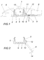
- the holder for a cover strip indicated by dash-dotted lines in FIG. 1 1 consists of a support profile, one on a base 2, for example with the help of screws 3 attachable fastening web 4 and two has from this fastening web 4 projecting bracket legs 5 on the cover strip 1 can be plugged in at different inclinations or heights is, for example, a height gradation between two floor coverings 6 and bridge 7.
- the fastening web 4 is laterally over the two bracket legs 5 extended to a free edge section 8, which like the web section between the mounting legs 5 with openings 9 for receiving is provided by fastening screws 3.
- the free one Edge section 8 to the web section between the bracket legs 5 a predetermined breaking point 10 connected by one of the underground 2 constriction 11 on the opposite side along the adjoining side Bracket leg 5 is formed.
- This predetermined breaking point 10 is by a Support approach 12 bridges this subsequent bracket leg 5, the free edge portion 8 of the fastening web 4 abuts and a quarter circle has adapted cross-sectional profile. If the free edge section 8 used to attach the mounting profile, as indicated in FIG.
- the support projection 12 of the bracket leg 5 prevents that in a Direction of arrow 13 on the cover strip 1 acting load of the two Bracket leg 5 connecting web portion of the mounting web 4 around The predetermined breaking point 10 is bent as a hinge axis from the base 2.
- the Bracket profile accordingly has one with conventional bracket profiles kind of comparable resilience.
- the free edge section 8 can along the subsequent bracket leg 5 are separated by this free Edge section 8 around the predetermined breaking point 10 as a hinge axis in the direction of the arrow 14 against the underside of the web section between the mounting legs 5 bent and thereby separated from this web section, as in the Fig. 2 is indicated by dash-dotted lines.
- a cross-sectionally U-shaped mounting profile which at corresponding Assembly conditions is used. However, it is only one Bracket profile required to either attach over the free Edge section 8 according to FIG. 1 or an attachment via the web section between the bracket legs 5 according to FIG. 2.
- bracket profile as a continuous rail or in the form of individual profile pieces can be formed, which are then at a mutual distance along the bridging paragraph or the joint to be bridged have to.
- bracket leg 5 is important, but only with a bracket profile Inclusion of a cover strip that can be removed via a predetermined breaking point provide the projecting edge portion of the fastening web, which consists of a given by the support approach of the subsequent bracket leg Stop position pivoted around the predetermined breaking point as a bending axis and thereby can be separated.
- bracket profile Inclusion of a cover strip that can be removed via a predetermined breaking point provide the projecting edge portion of the fastening web, which consists of a given by the support approach of the subsequent bracket leg Stop position pivoted around the predetermined breaking point as a bending axis and thereby can be separated.
- such mounting profiles can not only in Floor area can be used, but wherever there are joints or To bridge gradations with a cover strip.
Landscapes
- Engineering & Computer Science (AREA)
- Architecture (AREA)
- Civil Engineering (AREA)
- Structural Engineering (AREA)
- Body Structure For Vehicles (AREA)
- Spinning Or Twisting Of Yarns (AREA)
- Building Environments (AREA)
Applications Claiming Priority (2)
| Application Number | Priority Date | Filing Date | Title |
|---|---|---|---|
| AT17512001 | 2001-11-07 | ||
| AT0175101A AT411375B (de) | 2001-11-07 | 2001-11-07 | Halterung für eine abdeckleiste |
Publications (2)
| Publication Number | Publication Date |
|---|---|
| EP1310613A2 true EP1310613A2 (fr) | 2003-05-14 |
| EP1310613A3 EP1310613A3 (fr) | 2003-11-12 |
Family
ID=3688820
Family Applications (1)
| Application Number | Title | Priority Date | Filing Date |
|---|---|---|---|
| EP02450233A Withdrawn EP1310613A3 (fr) | 2001-11-07 | 2002-10-16 | Dispositif de maintien d'un couvre-joint |
Country Status (2)
| Country | Link |
|---|---|
| EP (1) | EP1310613A3 (fr) |
| AT (1) | AT411375B (fr) |
Cited By (11)
| Publication number | Priority date | Publication date | Assignee | Title |
|---|---|---|---|---|
| WO2005083196A1 (fr) * | 2004-02-27 | 2005-09-09 | Neuhofer Franz Jun | Dispositif pour compenser une difference de hauteur entre deux surfaces de sol |
| US7020846B2 (en) | 2000-12-27 | 2006-03-28 | Nokia Corporation | Display generating device |
| FR2881158A1 (fr) * | 2005-01-25 | 2006-07-28 | Depro France Sarl | Ensemble de finition multifonction pour revetement de sol, et procede d'installation dudit ensemble |
| BE1016403A5 (nl) * | 2005-01-12 | 2006-10-03 | Flooring Ind Ltd | Afwerkset voor een vloerbedekking en houder, alsmede afwerkprofiel, voor een afwerkset. |
| DE102005056439A1 (de) * | 2005-11-26 | 2007-05-31 | PUR Möbelprofile-Vertriebs-GmbH | Profilleiste zur Verwendung im Innenausbau sowie Bausatz einschließlich einer solchen Profilleiste |
| FR2908803A1 (fr) * | 2006-11-17 | 2008-05-23 | Dinac Soc Par Actions Simplifi | Nez de marche et analogue |
| DE202005021679U1 (de) | 2005-01-12 | 2009-03-12 | Flooring Industries Ltd. | Satz von Einzelteilen zum Formen eines Abdeckprofils und Abdeckprofil |
| EP2292872A1 (fr) | 2009-09-04 | 2011-03-09 | Flooring Industries Limited, SARL | Ensemble de finition pour un revetement de sol |
| US8186118B2 (en) | 2004-02-27 | 2012-05-29 | Neuhofer Franz Jun | Covering device for floor coverings |
| US8205410B2 (en) * | 2005-05-23 | 2012-06-26 | Pergo (Europe) Ab | Transition molding and installation methods therefor |
| US8245474B2 (en) | 2006-02-07 | 2012-08-21 | Flooring Industries Limited, Sarl | Finishing profile for a floor covering and methods for manufacturing such finishing profile |
Families Citing this family (3)
| Publication number | Priority date | Publication date | Assignee | Title |
|---|---|---|---|---|
| US20030084634A1 (en) | 2001-11-08 | 2003-05-08 | Oliver Stanchfield | Transition molding |
| EP2076638A4 (fr) | 2006-10-18 | 2011-05-11 | Pergo AG | Joints ayant des surfaces disparates |
| CA2697573A1 (fr) | 2009-03-27 | 2010-09-27 | Pergo (Europe) Ab | Ensemble de recouvrement de joints, trousse comprenant cet ensemble et procede d'installation connexe |
Citations (2)
| Publication number | Priority date | Publication date | Assignee | Title |
|---|---|---|---|---|
| AT4088B (fr) | 1900-01-03 | 1901-05-10 | Siegfried Eisenstein | |
| WO1999001628A1 (fr) | 1997-07-02 | 1999-01-14 | Herm. Friedr. Künne Gmbh & Co. | Systeme de chevauchement |
Family Cites Families (6)
| Publication number | Priority date | Publication date | Assignee | Title |
|---|---|---|---|---|
| AT193592B (de) * | 1954-04-23 | 1957-11-25 | Franz Buechler | Halte- und Fugenabdeckrahmen für Platten |
| FR1252603A (fr) * | 1955-02-12 | 1961-02-03 | Dispositif d'assemblage de parois ou analogues | |
| GB8909020D0 (en) * | 1989-04-20 | 1989-06-07 | Bruce Aidan S | Trim strip |
| US5769562A (en) * | 1997-01-08 | 1998-06-23 | Jones; Stephen | Edge restraint apparatus having variable length sections |
| AT3011U1 (de) * | 1998-04-20 | 1999-08-25 | Neuhofer Franz Jun | Vorrichtung zum befestigen längsgenuteter abdeckleisten |
| FR2785316B1 (fr) * | 1998-10-30 | 2001-01-19 | Michel Grosjean | Couvre-joint demontable |
-
2001
- 2001-11-07 AT AT0175101A patent/AT411375B/de active
-
2002
- 2002-10-16 EP EP02450233A patent/EP1310613A3/fr not_active Withdrawn
Patent Citations (2)
| Publication number | Priority date | Publication date | Assignee | Title |
|---|---|---|---|---|
| AT4088B (fr) | 1900-01-03 | 1901-05-10 | Siegfried Eisenstein | |
| WO1999001628A1 (fr) | 1997-07-02 | 1999-01-14 | Herm. Friedr. Künne Gmbh & Co. | Systeme de chevauchement |
Cited By (19)
| Publication number | Priority date | Publication date | Assignee | Title |
|---|---|---|---|---|
| US7020846B2 (en) | 2000-12-27 | 2006-03-28 | Nokia Corporation | Display generating device |
| US7814720B2 (en) | 2004-02-27 | 2010-10-19 | Neuhofer Franz Jun | Device for bridging a difference in height between two floor surfaces |
| US7908819B2 (en) | 2004-02-27 | 2011-03-22 | Neuhofer Jr Franz | Device for bridging a difference in height between two floor surfaces |
| US8186118B2 (en) | 2004-02-27 | 2012-05-29 | Neuhofer Franz Jun | Covering device for floor coverings |
| WO2005083196A1 (fr) * | 2004-02-27 | 2005-09-09 | Neuhofer Franz Jun | Dispositif pour compenser une difference de hauteur entre deux surfaces de sol |
| BE1016403A5 (nl) * | 2005-01-12 | 2006-10-03 | Flooring Ind Ltd | Afwerkset voor een vloerbedekking en houder, alsmede afwerkprofiel, voor een afwerkset. |
| DE202005021679U1 (de) | 2005-01-12 | 2009-03-12 | Flooring Industries Ltd. | Satz von Einzelteilen zum Formen eines Abdeckprofils und Abdeckprofil |
| US8747596B2 (en) | 2005-01-12 | 2014-06-10 | Flooring Industries Limited, Sarl | Finishing set for floor covering and holder, as well as finishing profile, for a finishing set, and method for manufacturing a finishing profile and a skirting board |
| US8286403B2 (en) | 2005-01-12 | 2012-10-16 | Flooring Industries Limited, Sarl | Finishing set for a floor covering and holder, as well as finishing profile, for a finishing set, and method for manufacturing a finishing profile and a skirting board |
| EP2343421A1 (fr) | 2005-01-12 | 2011-07-13 | Flooring Industries Ltd. | Ensemble de finition pour un revêtement de sol et profile de finition |
| US8161708B2 (en) | 2005-01-12 | 2012-04-24 | Flooring Industries Limited, Sarl | Finishing set for a floor covering and holder, as well as finishing profile, for a finishing set, and method for manufacturing a finishing profile and a skirting board |
| FR2881158A1 (fr) * | 2005-01-25 | 2006-07-28 | Depro France Sarl | Ensemble de finition multifonction pour revetement de sol, et procede d'installation dudit ensemble |
| US8205410B2 (en) * | 2005-05-23 | 2012-06-26 | Pergo (Europe) Ab | Transition molding and installation methods therefor |
| DE102005056439A1 (de) * | 2005-11-26 | 2007-05-31 | PUR Möbelprofile-Vertriebs-GmbH | Profilleiste zur Verwendung im Innenausbau sowie Bausatz einschließlich einer solchen Profilleiste |
| DE102005056439B4 (de) * | 2005-11-26 | 2011-03-31 | PUR Möbelprofile-Vertriebs-GmbH | Profilleiste zur Verwendung im Innenausbau sowie Bausatz einschließlich einer solchen Profilleiste |
| US8245474B2 (en) | 2006-02-07 | 2012-08-21 | Flooring Industries Limited, Sarl | Finishing profile for a floor covering and methods for manufacturing such finishing profile |
| US8245473B2 (en) | 2006-02-07 | 2012-08-21 | Flooring Industries Limited, Sarl | Finishing profile for a floor covering and methods for manufacturing such finishing profile |
| FR2908803A1 (fr) * | 2006-11-17 | 2008-05-23 | Dinac Soc Par Actions Simplifi | Nez de marche et analogue |
| EP2292872A1 (fr) | 2009-09-04 | 2011-03-09 | Flooring Industries Limited, SARL | Ensemble de finition pour un revetement de sol |
Also Published As
| Publication number | Publication date |
|---|---|
| AT411375B (de) | 2003-12-29 |
| EP1310613A3 (fr) | 2003-11-12 |
| ATA17512001A (de) | 2003-05-15 |
Similar Documents
| Publication | Publication Date | Title |
|---|---|---|
| EP0952276B1 (fr) | Kit avec moulure de couverture et dispositif de fixation | |
| DE10338816B3 (de) | Halterung für eine Platte, insbesondere für eine Glasscheibe | |
| DE10107864C2 (de) | Halteelement für Abdeckleisten | |
| EP1310613A2 (fr) | Dispositif de maintien d'un couvre-joint | |
| EP1010836A2 (fr) | Dispositif pour aménager la transition entre deux sections de revêtement de sol juxtaposés de hauteurs différentes | |
| EP0201834A2 (fr) | Support à bras à position continûment réglable | |
| DE202004000706U1 (de) | Profilschienensystem zur Überprüfung von Bodenbelagsübergängen | |
| DE3925302C2 (fr) | ||
| EP1136632A1 (fr) | Support au moins d'un panneau de verre de facade rideau | |
| DE10044969B4 (de) | Wandprofilleiste | |
| DE3246725A1 (de) | Aufhaengevorrichtung fuer wandbekleidungsplatten und unter verwendung derartiger aufhaengevorrichtungen aufgebaute plattenverankerungen | |
| DE20113359U1 (de) | Montagerahmen zur Befestigung von mindestens einem Sonnenkollektor | |
| DE102018103311B3 (de) | Basisprofil einer Fußbodenprofilanordnung | |
| DE3016064A1 (de) | Tragschiene als bausatzteil fuer die erstellung abgehaengter decken o.dgl. | |
| EP3712354A1 (fr) | Plateforme de coffrage | |
| DE3245851A1 (de) | Gelaender | |
| DE29912555U1 (de) | Konsoleinrichtung für eine Gerüstvorrichtung | |
| DE102007030925A1 (de) | Hakenträgersystem | |
| EP0307796A1 (fr) | Ecran anti-éblouissant | |
| DE20103385U1 (de) | Computertisch | |
| DE4114328A1 (de) | Vorrichtung zum haengenden befestigen eines konsolgeruestelements | |
| DE8417333U1 (de) | Abhaenge-vorrichtung fuer c-foermige tragschienen von unterdecken od. dgl. | |
| DE202016003333U1 (de) | Befestigungssystem | |
| EP0666380B1 (fr) | Dispositif pour la fixation de poteaux de balcon | |
| DE8518489U1 (de) | Unterkonstruktion für abhängende Unterdecken o.dgl. Verkleidungen |
Legal Events
| Date | Code | Title | Description |
|---|---|---|---|
| PUAI | Public reference made under article 153(3) epc to a published international application that has entered the european phase |
Free format text: ORIGINAL CODE: 0009012 |
|
| AK | Designated contracting states |
Designated state(s): AT BE BG CH CY CZ DE DK EE ES FI FR GB GR IE IT LI LU MC NL PT SE SK TR |
|
| AX | Request for extension of the european patent |
Extension state: AL LT LV MK RO SI |
|
| PUAL | Search report despatched |
Free format text: ORIGINAL CODE: 0009013 |
|
| AK | Designated contracting states |
Kind code of ref document: A3 Designated state(s): AT BE BG CH CY CZ DE DK EE ES FI FR GB GR IE IT LI LU MC NL PT SE SK TR |
|
| AX | Request for extension of the european patent |
Extension state: AL LT LV MK RO SI |
|
| 17P | Request for examination filed |
Effective date: 20031212 |
|
| AKX | Designation fees paid |
Designated state(s): AT BE BG CH CY CZ DE DK EE ES FI FR GB GR IE IT LI LU MC NL PT SE SK TR |
|
| GRAP | Despatch of communication of intention to grant a patent |
Free format text: ORIGINAL CODE: EPIDOSNIGR1 |
|
| STAA | Information on the status of an ep patent application or granted ep patent |
Free format text: STATUS: THE APPLICATION IS DEEMED TO BE WITHDRAWN |
|
| 18D | Application deemed to be withdrawn |
Effective date: 20080208 |