EP1310338A2 - Simulationssystem - Google Patents
Simulationssystem Download PDFInfo
- Publication number
- EP1310338A2 EP1310338A2 EP02257698A EP02257698A EP1310338A2 EP 1310338 A2 EP1310338 A2 EP 1310338A2 EP 02257698 A EP02257698 A EP 02257698A EP 02257698 A EP02257698 A EP 02257698A EP 1310338 A2 EP1310338 A2 EP 1310338A2
- Authority
- EP
- European Patent Office
- Prior art keywords
- dimensional
- dimensional model
- information
- operating
- simulation system
- Prior art date
- Legal status (The legal status is an assumption and is not a legal conclusion. Google has not performed a legal analysis and makes no representation as to the accuracy of the status listed.)
- Ceased
Links
- 238000004088 simulation Methods 0.000 title claims abstract description 92
- 230000002093 peripheral effect Effects 0.000 claims description 23
- 238000003466 welding Methods 0.000 abstract description 5
- 238000000034 method Methods 0.000 description 19
- 238000013500 data storage Methods 0.000 description 10
- 238000004891 communication Methods 0.000 description 6
- 230000004048 modification Effects 0.000 description 5
- 238000012986 modification Methods 0.000 description 5
- 238000004364 calculation method Methods 0.000 description 4
- 238000010276 construction Methods 0.000 description 2
- 238000010586 diagram Methods 0.000 description 2
- 230000008676 import Effects 0.000 description 2
- 230000008569 process Effects 0.000 description 2
- 239000007787 solid Substances 0.000 description 2
- 101100326580 Arabidopsis thaliana CAD4 gene Proteins 0.000 description 1
- 101100123053 Arabidopsis thaliana GSH1 gene Proteins 0.000 description 1
- 101150081304 CAD2 gene Proteins 0.000 description 1
- 101150096994 Cdx1 gene Proteins 0.000 description 1
- 101100381325 Saccharomyces cerevisiae (strain ATCC 204508 / S288c) PCA1 gene Proteins 0.000 description 1
- 230000004913 activation Effects 0.000 description 1
- 230000009466 transformation Effects 0.000 description 1
Images


Classifications
-
- B—PERFORMING OPERATIONS; TRANSPORTING
- B25—HAND TOOLS; PORTABLE POWER-DRIVEN TOOLS; MANIPULATORS
- B25J—MANIPULATORS; CHAMBERS PROVIDED WITH MANIPULATION DEVICES
- B25J9/00—Programme-controlled manipulators
- B25J9/16—Programme controls
- B25J9/1656—Programme controls characterised by programming, planning systems for manipulators
- B25J9/1671—Programme controls characterised by programming, planning systems for manipulators characterised by simulation, either to verify existing program or to create and verify new program, CAD/CAM oriented, graphic oriented programming systems
-
- G—PHYSICS
- G05—CONTROLLING; REGULATING
- G05B—CONTROL OR REGULATING SYSTEMS IN GENERAL; FUNCTIONAL ELEMENTS OF SUCH SYSTEMS; MONITORING OR TESTING ARRANGEMENTS FOR SUCH SYSTEMS OR ELEMENTS
- G05B2219/00—Program-control systems
- G05B2219/30—Nc systems
- G05B2219/40—Robotics, robotics mapping to robotics vision
- G05B2219/40317—For collision avoidance and detection
-
- G—PHYSICS
- G05—CONTROLLING; REGULATING
- G05B—CONTROL OR REGULATING SYSTEMS IN GENERAL; FUNCTIONAL ELEMENTS OF SUCH SYSTEMS; MONITORING OR TESTING ARRANGEMENTS FOR SUCH SYSTEMS OR ELEMENTS
- G05B2219/00—Program-control systems
- G05B2219/30—Nc systems
- G05B2219/40—Robotics, robotics mapping to robotics vision
- G05B2219/40323—Modeling robot environment for sensor based robot system
Definitions
- the present invention relates to a simulation system in which three-dimensional models of peripheral equipment and workpiece which are placed near an operating machine to be simulated such as a robot and a machine tool are generated, and these models are used with a three-dimensional model of the operating machine to be simulated.
- a preferred embodiment of the present invention provides a simulation system that enables an off-line simulation through rapid and accurate construction of a three-dimensional model of the system comprising an operating machine, its peripheral equipment, and others by importing two-dimensional information of the operating machine and its peripheral equipment prepared in a CAD system.
- the present invention is applied to a simulation system that performs a practical simulation by combining a three-dimensional model of an operating machine such as a robot and a machine tool, with three-dimensional model(s) of the peripheral equipment and the workpiece.
- the above described simulation system comprises means for storing a three-dimensional model of an operating machine, and means for inputting drawing information representing at least one two-dimensional shape of peripheral equipment or a workpiece.
- the above described drawing information includes three-dimensional layout information for laying out the two-dimensional shape in a three-dimensional manner and operating-point information to indicate the positions at which the operating machine is operated.
- the simulation system comprises three-dimensional model generation means for assembling three-dimensional model(s) of the peripheral equipment and the workpiece by laying out the two-dimensional shape on a screen of the simulation system based on the three-dimensional layout information, and means for operating the three-dimensional model of the operating machine on the screen based on the operating-point information read out from the above described drawing information.
- the simulation system comprises means for storing a three-dimensional model of an operating machine, means for acquiring operating-point information representing the position(s) at which the operating machine is operated, and means for inputting the drawing information representing at least one two-dimensional shape of the peripheral equipment or the workpiece.
- the drawing information includes three-dimensional layout information to lay out a two-dimensional shape in a three-dimensional manner.
- the simulation system comprises three-dimensional model generation means for assembling three-dimensional models of the peripheral equipment and the workpiece by laying out the two-dimensional shape on the screen of the simulation system based on the above described three-dimensional layout information, and means for operating the three-dimensional model of the operating machine on the screen based on the acquired operating-point information.
- the three-dimensional model generation means includes means for creating a three-dimensional shape by providing a thickness to an arbitrary portion of a plane or line of a two-dimensional shape indicated in the drawing information. It is also preferable that the drawing information is projection drawings of at least two directions, and the three-dimensional model generation means creates three-dimensional models based on the projection drawings of at least two directions and each of the directions.
- the projection directions are two mutually perpendicular directions, and the three-dimensional information of an original line segment is determined based on the position information of four points which are obtained by choosing both ends of the corresponding projected line segment on each projection drawing of the two directions.
- the projection directions are two mutually perpendicular directions as described above, and the three-dimensional information of an original circle is determined based on the position information of six points obtained by choosing three points in the corresponding projected circle and three points in the corresponding projected line segment on each projection drawing of the two directions.
- the two projection drawings may be any combination of mutually perpendicular projection directions selected from a front view, a right side view, a left side view, a top view, a bottom view, and a rear view, based on a trigonometry or mono-angular projection.
- the system preferably comprises means for storing an instruction program or a time chart of the operating machine, and means for operating the three-dimensional model of the operating machine on the screen according to the instruction program or the time chart.
- the present invention may be applied to the cases in which the simulation target includes a plurality of operating machines.
- three-dimensional models, two-dimensional shape information, and layout position information (not always all of them) of an operating machine such as a robot and a machine tool, and surrounding objects such as peripheral equipment and a workpiece may be inputted to the simulation system directly or indirectly via, for example, a communication line, an electronic information medium, or the like.
- position and posture information may be added to the two-dimensional shape information so that it is laid out as a three-dimensional line segment or plane in a virtual three-dimensional space to create a simplified three-dimensional model.
- a simplified three-dimensional model may be prepared for the peripheral equipment and the workpiece to enable rapid execution of a simulation.
- a front view and a right side view of the workpiece prepared by the orthographic projection method may be read in to instruct the position in each view at which a specific point of the workpiece is indicated for each view.
- the relative positions of two surfaces may be determined.
- a three-dimensional model of the workpiece may be completed by using a known three-dimensional model generation means such as a pushing-out of element exploiting the two drawings .
- Using two drawings makes it easy to generate a three-dimensional model.
- the layout information of the system components such as a workpiece as well as two-dimensional shape information and three-dimensional model makes it possible to lay out the three-dimensional model in a virtual three-dimensional space.
- importing a plan view of system layout may make the system construction easy. Also by indicating the layout reference points of the workpiece and others in the layout plan view by symbols, it is made possible to lay out the three-dimensional model of the workpiece based on the symbols . Also, an operating-point sequence of a robot may be read in to rapidly perform a simulation. The operating-point sequence information may be stored in the simulation system or may be imported from the information stored in a CAD system.
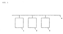
- FIG. 1 shows one example of an arrangement for importing various data from a CAD system in each example of the invention.
- reference numeral 1 denotes a simulation system
- the simulation system 1 is connected to a 2D-CAD system 2 and a 3D-CAD system 3 through a suitable communication line 4.
- the 2D-CAD system 2 and the 3D-CAD system 3 have CAD functions (processing, storing, input/output, etc.) to mainly deal with not higher than two-dimensional data and not higher than three-dimensional data respectively. In some cases, a CAD system having both functions may be utilized.
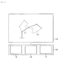
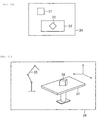
- Fig. 2 is a block diagram to show the configuration of substantial parts of the simulation system 1.
- the entire simulation system comprises a display part to provide a display screen 13 and a main part 14.
- the main part 14 is provided with an animation calculation display unit 15, a data storage unit 16, and motion calculation processing unit 17 of the operating machine.
- various parts of the simulation system are provided, as needed, with a keyboard, mouse, or the like for manually editing, modifying, and inputting the program data, parameter data, instructions, or the like.
- a main CPU which is not shown, governs each part of the simulation system according to the system program or the like stored in the data storage unit 16.
- the sending and receiving of the data via the communication line 4 is performed through a suitable input/output interface (not shown) .
- program data and parameters necessary for executing the processing in each example of the invention are stored in the data storage unit 16, and the activation, readout, writing, modification of them are controlled by the main CPU.
- the two-dimensional geometric information created by a CAD system for example, by the CAD system 2 independent of the simulation system 1 is imported into the simulation system 1 through an electric communication line 4 or an electronic medium.
- a two-dimensional drawing 21 of the workpiece as shown in Fig. 8A is provided in the CAD system 2.
- the two-dimensional drawing 21 of the workpiece consists of a top view, a front view, and a right side view, and the data to identify the contour of the workpiece on these views are outputted in a file format.
- the simulation system 1 imports this file output.
- the transformation of data record format etc. are required, and for that end, commercially available software 'ROBOGUIDE'® may be used.
- the contour of the workpiece is laid out on the screen 13 of the simulation system 1 using the imported two-dimensional geometric information.
- the workpiece is laid out on the screen 13 as a two-dimensional drawing without modification, for example, by displaying its front view or top view.
- the layout position is determined to be a position considered to better correspond to real operation condition from other information (where layout information is not inputted from a CAD system).
- layout information is not inputted from a CAD system.
- by specifying the orientation of the front view data of the workpiece it is possible to lay out the workpiece on the screen 13 displaying it in a three-dimensional manner as denoted by reference numeral 21a in Fig. 8B.
- a robot is laid out on the screen 13.
- the data of the three-dimensional model of the robot which is created in advance and stored in the data storage unit 16, are used to display the three-dimensional model 11 of the robot (see Fig. 2) on the screen 13.
- the display position (layout position) of the three-dimensional model 11 of the robot is determined to be a position which is considered to better correspond to real operation condition from other information (wherein the layout information is not inputted from the CAD system).
- Fig. 9B shows an example in which a three-dimensional model 102 of the workpiece and a three-dimensional model 103 of the robot are aligned and simultaneously displayed on the screen 104 of the simulation system 1.
- the CAD drawing of the workpiece is assumed to be one shown by reference numeral 101 in Fig. 9A (a right side view, a left side view, a top view, and a bottom view).
- the three-dimensional model 102 of the workpiece is created in the simulation system 1 based on the data imported from the CAD system.
- the three-dimensional model 103 of the robot is created in advance and stored in the data storage unit 16.
- an operating-point sequence for example, a sequence of welding points
- a motion program is created from this operating-point sequence. Explanation of the creation of the motion program from the operating-point sequence is omitted since that is similar to an ordinary off-line programming.
- the robot simulation is performed according to the data of this motion program.
- the motion locus 12 of the robot (generally an operating machine) is displayed on the screen 13 in an animation format. That is, motion locus 12 is displayed in an animation format using the motion program data including the data specifying the operating-point sequence by means of the animation calculation display unit 15 and the motion calculation processing unit 17 of the operating machine. Since this technique is well known, its detailed explanation is omitted.
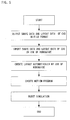
- the layout image of the workpiece is omitted. Also, the above described procedure may be briefly shown by a flowchart in Fig. 3.
- the workpiece which is imported from the CAD system 2 and laid out on the screen 13 of the simulation system 1 is displayed in a two-dimensional shape.
- this data it is possible to modify this data to lay them out on the screen 13 as a three-dimensional model of lines and planes.
- the present embodiment will describe a simple example of such case.
- the two-dimensional data imported from the CAD system 2 are added with position information in a virtual three-dimensional space displayed on the screen 13 to create a three-dimensional model consisting of lines and planes to be laid out on the screen 13.
- a simple model is sufficient for desired simulation, the creation of a three-dimensional model may be simplified.
- the procedure according to this example is as follows.
- Two-dimensional geometry information created by a CAD system for example, the CAD system 2 independent of the simulation system 1, are imported into the simulation system 1 through an electric communication line 4 or an electronic medium.
- the contour data of the two-dimensional drawing 21 (a top view, a front view, and a right side view) of the workpiece as shown in Fig. 8A are outputted in a file format.
- These data are, as in the case of the first embodiment, stored in the data storage unit 16 temporarily as two-dimensional drawing data by using commercially available software 'ROBOGUIDE'®.
- At least two drawings created by the orthographic projection method are imported from the CAD system, and a three-dimensional model is created by indicating the positional relationship between the two drawings. For example, when the two drawings are a front view and a right side view (see Fig. 8A), it is indicated that the imported drawings are a front view and a right side view. Also, by selecting the same position on each of the two drawings, the positional relationship of the two drawings is given. Since, in these two drawings, three-dimensional shape information is written, the depth of any part of the object can be easily specified while the drawings being watched.
- three-dimensional models are created by means of techniques of generating three-dimensional models used in existing three-dimensional CAD systems such as pushing-out and cutting-off of any part of the object. Since the operator can perform the creation of a three-dimensional model while watching the two drawings, he/she can perform pushing-out or cutting-off precisely thereby creating the three-dimensional model more precisely and rapidly. Moreover, data processing and screen display tools, which are necessary for the creation of such three-dimensional models, can be provided by commercially available software 'ROBOGUIDE'®. A created three-dimensional model of a workpiece looks like the three-dimensional model 23a shown in Fig. 8C. Such a three-dimensional model, which has been created by using projection data of two or more directions such as a front view and a side view and further making necessary modifications of those data, is called an "interactively created three-dimensional model.”
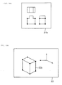
- Figs. 10A and 10B show, on the two-dimensional CAD drawing 21, a middle step of creating a three-dimensional model 23b in which three-dimensional position information (see small solid circles in Fig. 10B) of the original line segment is obtained based on the position information of four points (see small solid circles in Fig. 10A) obtained by selectively specifying both ends of a corresponding projected line segment on each projection drawing of two directions (for example, a front view and a side view).
- three-dimensional information for an original circle may be obtained based on the position information of six points obtained by selecting three points from each of a corresponding projected circle and a projected line segment on each of the projection drawings of two directions.
- the robot is laid out on the screen 13.
- the data of a three-dimensional model of the robot which has been prepared in advance and stored in the data storage unit 16, are used to display the three-dimensional model 11 (see Fig. 2) of the robot on the screen 13.
- the display position (layout position) of the three-dimensional model 11 of the robot is determined in such a way that it corresponds to the actual operation situation from other information (in this case, the layout information is not imported from the CAD system).
- an operating-point sequence (for example, sequence of welding points) is created by specifying a sequence of points, line segments, or planes using the data of the three-dimensional model 23a or the shape data of other workpieces imported from the CAD system 2 as needed. Then a motion program is created from the operating-point sequence.
- the creation of a motion program from an operating-point sequence is similar to an ordinary off-line programming, and therefore its explanation is omitted.
- a robot simulation is performed according to the data of this program.
- a motion locus 12 of the robot (generally an operating machine) is displayed on the screen 13 in an animation format.
- the layout image of the workpiece is omitted on the screen 13 in Fig. 2, the image to be displayed thereon is one that will be produced by superimposing the screen 22 of Fig. 8C on the screen 13 of Fig. 2.
- the process described so far may be summarized by a flowchart shown in Fig. 4.
- the layout position as well as two-dimensional shape information or three-dimensional model of peripheral equipment, operating machines, and workpiece are imported from the CAD system 2 or 3. Based on this layout information, the peripheral equipment, operating machine and workpiece are laid out in a virtual three-dimensional space displayed on the screen of the simulation system 1. By doing this, the system of a three-dimensional model can be constructed easily.
- the procedure in the present embodiment is as follows.
- Two-dimensional or three-dimensional geometric information and layout information concerning the workpiece and others are imported to the simulation system 1 via an electric communication line 4 or an electronic medium.
- the layout information includes a plurality of plan view data: a layout plan 31 of an operating machine (a robot), a layout plan 32 of a workpiece, and a layout plan 33 of a worktable, as shown in Fig. 11A.
- the layout data including such data and the two-dimensional shape data of the workpiece and the worktable are outputted from the CAD2 in a file format. These data are temporarily stored in the data storage unit 16 by utilizing the commercially available software 'ROBOGUIDE'®. These data are stored in the data storage unit 16 even when the layout information is given as three-dimensional data.
- the two-dimensional shape data of the workpiece and worktable it is possible to utilize at least two drawings that are created by the orthogonal projection method as described in the second embodiment. From these drawings, as described in the second embodiment, three-dimensional models of the workpiece and worktable are created.
- the software for data processing and screen display, which is needed for creating such three-dimensional models, can also be provided by the commercially available software 'ROBOGUIDE'®.
- An example of the created three-dimensional models of the workpiece and worktable includes three-dimensional models 36 and 37 shown in Fig. 11B.
- the three-dimensional model 35 of the operating machine (a robot) has been created in advance and is stored in the data storage unit 16. But in some cases, the data prepared in the CAD system 3 may be used by modifying them as needed.
- the prepared three-dimensional models 35, 36, and 37 for the operating machine (a robot), the workpiece, and the worktable are laid out on the screen 38 of the simulation system 1.
- the layout positions of the component models 35 to 37 are determined based on the layout information (plan view data or three-dimensional layout data) imported from the CAD system 2 or 3.
- the layout positions of the three-dimensional models 35 to 37 on the screen 38 can be determined by, for example, specifying (for example, clicking on the screen 38) vertex points (one or more) of the layout figures 31 to 33 of each component.
- the software for such data processing needed for layout and screen display can be prepared by commercially available software 'ROBOGUIDE'®.
- an operating-point sequence for example, a sequence of welding points
- a motion program is created from the operating-point sequence.
- the creation of the motion program from the operating-point sequence is similar to an ordinary off-line programming, and therefore its explanation is omitted.
- a robot simulation is performed according to the data of this motion program.
- a motion locus 12 of the robot (generally an operating machine) is displayed on the screen 13 (screen 38 in Fig. 11B) in an animation format.
- the layout images of the workpiece and the worktable are omitted on the screen 13 in Fig. 2, an image similar to one which is formed by superimposing the screen 38 in Fig. 11B on the locus 12 shown in Fig. 2 is supposed to be displayed.
- the above described procedure can be briefly summarized by a flowchart in Fig. 5 (a case in which three-dimensional layout information is prepared) or Fig. 6 (a case in which the layout information is prepared as a plan view) . In these flowcharts, the description of the step of creating the three-dimensional models is omitted.
- the CAD system 2 or 3 is provided with operating-point information as well.
- the CAD system 2 or 3 is provided with shape information (two-dimensional data or three-dimensional data) of the peripheral equipment, the operating machine and the workpiece, their layout information, and operating-point information as well.
- the operating-point information which is the position information for operating the operating machine (a robot)
- the operating-point information can be imported from the CAD system and or from a drawing created by the CAD system to easily specify the motion of the robot.
- the shape data and layout data of the peripheral equipment, the machine, the hand, and the welding gun as well as the operating-point sequence is outputted in a file format from the CAD system. Then these data are imported to the simulation system 1 by using the commercially available software 'ROBOGUIDE'®. Based on the imported layout data, the imported shape data are laid out. Also, a motion program of the robot is created from the operating-point sequence. With patterns of robot motion program (operating points are not yet defined) and time charts being stored in the simulation system 1, it is possible to complete the motion program by importing the above described operating-point sequence into the pattern or the time chart of the motion program. This type of method is well known, and therefore its explanation is omitted.
- the motion program is executed to perform a robot simulation.
- the three-dimensional models of the robot and the surrounding objects (workpiece etc.) as well as a motion locus of the robot are displayed on the screen 13 of the simulation system 1.
- the above described procedure can be briefly summarized in a flowchart shown in Fig. 7.
- the present invention by importing a three-dimensional model or two-dimensional drawing created by a CAD system in advance and their layout information into the simulation system from a CAD system or the like, it is made possible to rapidly and accurately construct a three-dimensional model of the above described system in a short time, thereby enabling an off-line simulation. It is also made possible to create a simplified three-dimensional model by utilizing two-dimensional shape information such as a plan view imported from the CAD system without any modification. Moreover, it is possible to easily create a three-dimensional model utilizing the two-dimensional shape information.
- this layout information also can be imported into the simulation system to rapidly and accurately layout three-dimensional models such as the robot in a virtual three-dimensional space to be displayed on the screen of the simulation system thereby enabling rapid execution of the simulation.
- operating points of the robot from a CAD system or drawings created by the CAD system, it is possible to eliminate the need for newly defining the operating points in the simulation system, thereby enabling rapid and accurate simulations.
Landscapes
- Engineering & Computer Science (AREA)
- Robotics (AREA)
- Mechanical Engineering (AREA)
- Numerical Control (AREA)
- Manipulator (AREA)
Applications Claiming Priority (2)
| Application Number | Priority Date | Filing Date | Title |
|---|---|---|---|
| JP2001346775 | 2001-11-12 | ||
| JP2001346775A JP3673749B2 (ja) | 2001-11-12 | 2001-11-12 | シミュレーション装置 |
Publications (2)
| Publication Number | Publication Date |
|---|---|
| EP1310338A2 true EP1310338A2 (de) | 2003-05-14 |
| EP1310338A3 EP1310338A3 (de) | 2004-10-06 |
Family
ID=19159881
Family Applications (1)
| Application Number | Title | Priority Date | Filing Date |
|---|---|---|---|
| EP02257698A Ceased EP1310338A3 (de) | 2001-11-12 | 2002-11-06 | Simulationssystem |
Country Status (3)
| Country | Link |
|---|---|
| US (1) | US7027963B2 (de) |
| EP (1) | EP1310338A3 (de) |
| JP (1) | JP3673749B2 (de) |
Cited By (8)
| Publication number | Priority date | Publication date | Assignee | Title |
|---|---|---|---|---|
| EP1424656A2 (de) * | 2002-11-29 | 2004-06-02 | Mori Seiki Co., Ltd. | Verfahren und Vorrichtung zur Erzeugung von dreidimensionalen Modelldaten für Werkzeugmaschine |
| WO2005124486A2 (en) * | 2004-06-15 | 2005-12-29 | Abb Ab | Method and system for off-line programming of multiple interacting robots |
| WO2006105917A1 (de) * | 2005-04-02 | 2006-10-12 | Daimlerchrysler Ag | Verfahren und vorrichtung zur simulation einer fertigungsanlage |
| EP1498792A3 (de) * | 2003-07-03 | 2009-04-08 | Fanuc Ltd | Vorrichtung zur Off- line Simulation von robotischen Arbeitsgängen |
| CN104626153A (zh) * | 2013-11-11 | 2015-05-20 | 株式会社安川电机 | 机器人模拟装置以及机器人模拟方法 |
| CN105291107A (zh) * | 2014-06-30 | 2016-02-03 | 株式会社安川电机 | 机器人模拟器及机器人模拟器的文件生成方法 |
| US9390203B2 (en) | 2004-06-15 | 2016-07-12 | Abb Ab | Method and system for off-line programming of multiple interacting robots |
| US10603788B2 (en) | 2016-09-05 | 2020-03-31 | Fanuc Corporation | Robot simulation apparatus |
Families Citing this family (20)
| Publication number | Priority date | Publication date | Assignee | Title |
|---|---|---|---|---|
| JP3819883B2 (ja) * | 2003-08-27 | 2006-09-13 | ファナック株式会社 | ロボットプログラム位置修正装置 |
| DE10352815B4 (de) * | 2003-11-12 | 2009-06-25 | Siemens Ag | Simulationsverfahren für eine Bearbeitung eines Werkstücks durch eine Werkzeugmaschine und korrespondierender Rechner |
| JP2006195971A (ja) * | 2004-12-16 | 2006-07-27 | Canon Inc | 三次元cadシステム |
| JP2007026061A (ja) * | 2005-07-15 | 2007-02-01 | Ritsumeikan | ハプティックビジョンに基づく3次元物体モデル生成方法及びハプティックビジョンシステム |
| JP2007286976A (ja) * | 2006-04-18 | 2007-11-01 | Fanuc Ltd | ロボットシミュレーション装置 |
| US7823479B2 (en) * | 2007-03-30 | 2010-11-02 | Nissan Technical Center North America, Inc. | Vehicle steering column structure |
| JP4653836B2 (ja) * | 2008-12-12 | 2011-03-16 | ファナック株式会社 | シミュレーション装置 |
| KR100968944B1 (ko) * | 2009-12-14 | 2010-07-14 | (주) 아이알로봇 | 로봇 동기화 장치 및 그 방법 |
| JP2011185650A (ja) * | 2010-03-05 | 2011-09-22 | Omron Corp | モデル作成装置およびモデル作成プログラム |
| US9415509B2 (en) * | 2011-11-04 | 2016-08-16 | Fanuc America Corporation | Robot teach device with 3-D display |
| JP2014100780A (ja) * | 2012-11-22 | 2014-06-05 | Dainippon Screen Mfg Co Ltd | 把持機構の軌道生成装置、把持機構の軌道生成方法、把持機構の軌道生成プログラム、記録媒体、ロボットプログラム作成装置 |
| JP5803952B2 (ja) * | 2013-02-15 | 2015-11-04 | 株式会社安川電機 | コントローラ、タイムチャート作成装置、コンピュータプログラム、情報記憶媒体、機器制御方法及びタイムチャート作成方法 |
| US9958854B2 (en) * | 2013-06-10 | 2018-05-01 | The Boeing Company | Systems and methods for robotic measurement of parts |
| JP5877857B2 (ja) | 2014-03-10 | 2016-03-08 | ファナック株式会社 | ワークの取出工程をシミュレーションするロボットシミュレーション装置 |
| JP6432494B2 (ja) * | 2015-11-30 | 2018-12-05 | オムロン株式会社 | 監視装置、監視システム、監視プログラムおよび記録媒体 |
| WO2017096605A1 (en) * | 2015-12-11 | 2017-06-15 | Abb Schweiz Ag | Robot off-line programming method and appartus using the same |
| JP6392817B2 (ja) * | 2016-08-04 | 2018-09-19 | ファナック株式会社 | シミュレーション装置 |
| JP7095262B2 (ja) * | 2017-11-10 | 2022-07-05 | 株式会社安川電機 | プログラミング支援装置、ロボットシステム及びプログラム生成方法 |
| US11926058B2 (en) * | 2017-12-28 | 2024-03-12 | Fuji Corporation | Information providing device, information providing method and program |
| CN109035389A (zh) * | 2018-07-02 | 2018-12-18 | 北京理工大学 | 一种部件装配仿真方法和装置 |
Citations (5)
| Publication number | Priority date | Publication date | Assignee | Title |
|---|---|---|---|---|
| US4879667A (en) * | 1984-02-03 | 1989-11-07 | Dr. Johannes Heidenhain Gmbh | Process for generating a computer model of an alterable structure |
| US5161101A (en) * | 1989-04-28 | 1992-11-03 | Nissan Motor Co., Ltd. | Method of forming automatic machine operation program |
| US6112133A (en) * | 1998-02-27 | 2000-08-29 | Imcs, Inc. | Visual system and method for generating a CNC program for machining parts with planar and curvilinear surfaces |
| EP1092513A2 (de) * | 1999-10-12 | 2001-04-18 | Fanuc Ltd | Graphische Anzeigevorrichtung für ein Robotersystem |
| US6290571B1 (en) * | 1999-01-05 | 2001-09-18 | Walter Ag | Virtual teach-in system |
Family Cites Families (12)
| Publication number | Priority date | Publication date | Assignee | Title |
|---|---|---|---|---|
| US4970666A (en) * | 1988-03-30 | 1990-11-13 | Land Development Laboratory, Inc. | Computerized video imaging system for creating a realistic depiction of a simulated object in an actual environment |
| JP2787883B2 (ja) | 1992-12-28 | 1998-08-20 | 三菱電機株式会社 | 三次元レーザ加工機用シミュレーション装置 |
| JP2627608B2 (ja) * | 1993-07-26 | 1997-07-09 | 日本アイ・ビー・エム株式会社 | ソリッドモデル合成装置及び合成方法 |
| JP3351900B2 (ja) * | 1994-06-27 | 2002-12-03 | 松下電工株式会社 | 3次元モデル造形方法とこれを利用した金型製作方法 |
| US5988862A (en) * | 1996-04-24 | 1999-11-23 | Cyra Technologies, Inc. | Integrated system for quickly and accurately imaging and modeling three dimensional objects |
| AUPO206596A0 (en) * | 1996-08-30 | 1996-09-26 | Anca Pty Ltd | Tool grinding simulation system |
| JPH10307935A (ja) | 1997-05-09 | 1998-11-17 | Hitachi Ltd | 3次元モデルの生成方法、および、3次元モデルの干渉検査方法 |
| JPH1166113A (ja) * | 1997-08-21 | 1999-03-09 | Nippon Steel Corp | 三次元データ作成システム及び三次元データ作成方法 |
| US6409596B1 (en) * | 1997-09-12 | 2002-06-25 | Kabushiki Kaisha Sega Enterprises | Game device and image displaying method which displays a game proceeding in virtual space, and computer-readable recording medium |
| US5990900A (en) * | 1997-12-24 | 1999-11-23 | Be There Now, Inc. | Two-dimensional to three-dimensional image converting system |
| JP2000187679A (ja) * | 1998-12-22 | 2000-07-04 | Dainippon Screen Mfg Co Ltd | パッケージ意匠シミュレーション方法、パッケージ意匠シミュレーション装置、およびパッケージ意匠シミュレーションプログラムを記録した記録媒体 |
| JP2001018679A (ja) | 1999-07-06 | 2001-01-23 | Toyota Motor Corp | 車両用ペダル装置 |
-
2001
- 2001-11-12 JP JP2001346775A patent/JP3673749B2/ja not_active Expired - Fee Related
-
2002
- 2002-11-04 US US10/286,863 patent/US7027963B2/en active Active
- 2002-11-06 EP EP02257698A patent/EP1310338A3/de not_active Ceased
Patent Citations (5)
| Publication number | Priority date | Publication date | Assignee | Title |
|---|---|---|---|---|
| US4879667A (en) * | 1984-02-03 | 1989-11-07 | Dr. Johannes Heidenhain Gmbh | Process for generating a computer model of an alterable structure |
| US5161101A (en) * | 1989-04-28 | 1992-11-03 | Nissan Motor Co., Ltd. | Method of forming automatic machine operation program |
| US6112133A (en) * | 1998-02-27 | 2000-08-29 | Imcs, Inc. | Visual system and method for generating a CNC program for machining parts with planar and curvilinear surfaces |
| US6290571B1 (en) * | 1999-01-05 | 2001-09-18 | Walter Ag | Virtual teach-in system |
| EP1092513A2 (de) * | 1999-10-12 | 2001-04-18 | Fanuc Ltd | Graphische Anzeigevorrichtung für ein Robotersystem |
Non-Patent Citations (1)
| Title |
|---|
| AUTORI VARI: "Manuale Cremonese di MECCANICA ELETTROTECNICA ELETTRONICA Parte generale - Vol. I" 1999, EDIZIONI CREMONESE , FIRENZE, ITALIA , XP002292199 Capitolo 6: Disegno assistito dall'elaboratore * section 4.2: AutoCAD 3D; figure 4.9 * * |
Cited By (13)
| Publication number | Priority date | Publication date | Assignee | Title |
|---|---|---|---|---|
| US7403648B2 (en) | 2002-11-29 | 2008-07-22 | Mori Seiki Co., Ltd. | Apparatus for generating three-dimensional model data |
| EP1424656A3 (de) * | 2002-11-29 | 2006-02-08 | Mori Seiki Co., Ltd. | Verfahren und Vorrichtung zur Erzeugung von dreidimensionalen Modelldaten für Werkzeugmaschine |
| EP1424656A2 (de) * | 2002-11-29 | 2004-06-02 | Mori Seiki Co., Ltd. | Verfahren und Vorrichtung zur Erzeugung von dreidimensionalen Modelldaten für Werkzeugmaschine |
| EP1498792A3 (de) * | 2003-07-03 | 2009-04-08 | Fanuc Ltd | Vorrichtung zur Off- line Simulation von robotischen Arbeitsgängen |
| WO2005124486A3 (en) * | 2004-06-15 | 2006-06-08 | Abb Ab | Method and system for off-line programming of multiple interacting robots |
| WO2005124486A2 (en) * | 2004-06-15 | 2005-12-29 | Abb Ab | Method and system for off-line programming of multiple interacting robots |
| US9104197B2 (en) | 2004-06-15 | 2015-08-11 | Abb Ab | Method and system for off-line programming of multiple interacting robots |
| US9390203B2 (en) | 2004-06-15 | 2016-07-12 | Abb Ab | Method and system for off-line programming of multiple interacting robots |
| WO2006105917A1 (de) * | 2005-04-02 | 2006-10-12 | Daimlerchrysler Ag | Verfahren und vorrichtung zur simulation einer fertigungsanlage |
| CN104626153A (zh) * | 2013-11-11 | 2015-05-20 | 株式会社安川电机 | 机器人模拟装置以及机器人模拟方法 |
| CN105291107A (zh) * | 2014-06-30 | 2016-02-03 | 株式会社安川电机 | 机器人模拟器及机器人模拟器的文件生成方法 |
| CN105291107B (zh) * | 2014-06-30 | 2017-09-19 | 株式会社安川电机 | 机器人模拟器及机器人模拟器的文件生成方法 |
| US10603788B2 (en) | 2016-09-05 | 2020-03-31 | Fanuc Corporation | Robot simulation apparatus |
Also Published As
| Publication number | Publication date |
|---|---|
| JP3673749B2 (ja) | 2005-07-20 |
| EP1310338A3 (de) | 2004-10-06 |
| US20030090489A1 (en) | 2003-05-15 |
| US7027963B2 (en) | 2006-04-11 |
| JP2003150220A (ja) | 2003-05-23 |
Similar Documents
| Publication | Publication Date | Title |
|---|---|---|
| US7027963B2 (en) | Simulation system | |
| JP6350037B2 (ja) | ロボットシミュレータおよびロボットシミュレータのファイル生成方法 | |
| US7447615B2 (en) | Simulation apparatus for robot operation having function of visualizing visual field by image capturing unit | |
| EP1425718B1 (de) | Gleichzeitige benutzung von 2d- und 3d-modellierungsdaten | |
| JP3797986B2 (ja) | ロボットオフラインシミュレーション装置 | |
| CN110434856B (zh) | 一种焊接控制方法、装置、存储介质及焊接机器人 | |
| JP2017094406A (ja) | シミュレーション装置、シミュレーション方法、およびシミュレーションプログラム | |
| CN105945942A (zh) | 一种机器人离线编程系统及方法 | |
| JP3347964B2 (ja) | 自動プログラミング装置および方法 | |
| US7092860B1 (en) | Hardware simulation systems and methods for vision inspection systems | |
| JP2000298734A (ja) | 3次元モデルの断面生成装置 | |
| JP2000003384A5 (de) | ||
| EP1638027A1 (de) | Produkt-teilekatalog-erzeugungsverfahren und -system | |
| US7088377B2 (en) | System and method for designing, synthesizing and analyzing computer generated mechanisms | |
| JPS62251905A (ja) | 対話形グラフイツク入力システム | |
| Gupta et al. | An intelligent environment for simulating mechanical assembly operations | |
| KR101530895B1 (ko) | 3차원 캐드로부터 2차원 캐드를 위한 오브젝트 데이터 추출 방법 및 2차원 캐드로부터 3차원 캐드를 위한 오브젝트 데이터 추출 방법 | |
| Sturgill et al. | Feature-based 3-d sketching for early stage design | |
| JPH02236704A (ja) | 動作シミュレーションシステム | |
| Lindberget | Automatic generation of robot targets: A first step towards a flexible robotic solution for cutting customized mesh tray | |
| Sanchez et al. | Representation of Robots in Matlab | |
| EP0620530A2 (de) | Verfahren und Vorrichtung zur Verwandlung von zweidimensionalen Daten in dreidimentsionalen Daten | |
| Muncaster | An interactive graphical simulation of CNC milling | |
| Arbab et al. | Toward CAM-Oriented CAD | |
| MILOJEVIĆ et al. | Virtual design and manufacturing |
Legal Events
| Date | Code | Title | Description |
|---|---|---|---|
| PUAI | Public reference made under article 153(3) epc to a published international application that has entered the european phase |
Free format text: ORIGINAL CODE: 0009012 |
|
| AK | Designated contracting states |
Designated state(s): AT BE BG CH CY CZ DE DK EE ES FI FR GB GR IE IT LI LU MC NL PT SE SK TR |
|
| AX | Request for extension of the european patent |
Extension state: AL LT LV MK RO SI |
|
| PUAL | Search report despatched |
Free format text: ORIGINAL CODE: 0009013 |
|
| AK | Designated contracting states |
Kind code of ref document: A3 Designated state(s): AT BE BG CH CY CZ DE DK EE ES FI FR GB GR IE IT LI LU MC NL PT SE SK TR |
|
| AX | Request for extension of the european patent |
Extension state: AL LT LV MK RO SI |
|
| RIC1 | Information provided on ipc code assigned before grant |
Ipc: 7B 25J 9/16 B Ipc: 7G 05B 19/4069 A |
|
| 17P | Request for examination filed |
Effective date: 20050105 |
|
| AKX | Designation fees paid |
Designated state(s): DE |
|
| 17Q | First examination report despatched |
Effective date: 20060720 |
|
| APBN | Date of receipt of notice of appeal recorded |
Free format text: ORIGINAL CODE: EPIDOSNNOA2E |
|
| APBR | Date of receipt of statement of grounds of appeal recorded |
Free format text: ORIGINAL CODE: EPIDOSNNOA3E |
|
| APBD | Information on interlocutory revision deleted |
Free format text: ORIGINAL CODE: EPIDOSDIRAPE |
|
| APBV | Interlocutory revision of appeal recorded |
Free format text: ORIGINAL CODE: EPIDOSNIRAPE |
|
| APAF | Appeal reference modified |
Free format text: ORIGINAL CODE: EPIDOSCREFNE |
|
| APBT | Appeal procedure closed |
Free format text: ORIGINAL CODE: EPIDOSNNOA9E |
|
| STAA | Information on the status of an ep patent application or granted ep patent |
Free format text: STATUS: THE APPLICATION HAS BEEN REFUSED |
|
| 18R | Application refused |
Effective date: 20101207 |