EP1308680B1 - Process and system for production of krypton and/or xenon by cryogenic air separation - Google Patents
Process and system for production of krypton and/or xenon by cryogenic air separation Download PDFInfo
- Publication number
- EP1308680B1 EP1308680B1 EP02023333A EP02023333A EP1308680B1 EP 1308680 B1 EP1308680 B1 EP 1308680B1 EP 02023333 A EP02023333 A EP 02023333A EP 02023333 A EP02023333 A EP 02023333A EP 1308680 B1 EP1308680 B1 EP 1308680B1
- Authority
- EP
- European Patent Office
- Prior art keywords
- krypton
- xenon
- column
- evaporator
- condenser
- Prior art date
- Legal status (The legal status is an assumption and is not a legal conclusion. Google has not performed a legal analysis and makes no representation as to the accuracy of the status listed.)
- Expired - Lifetime
Links
- 229910052724 xenon Inorganic materials 0.000 title claims abstract description 48
- FHNFHKCVQCLJFQ-UHFFFAOYSA-N xenon atom Chemical compound [Xe] FHNFHKCVQCLJFQ-UHFFFAOYSA-N 0.000 title claims abstract description 48
- 229910052743 krypton Inorganic materials 0.000 title claims abstract description 42
- DNNSSWSSYDEUBZ-UHFFFAOYSA-N krypton atom Chemical compound [Kr] DNNSSWSSYDEUBZ-UHFFFAOYSA-N 0.000 title claims abstract description 42
- 238000000034 method Methods 0.000 title claims abstract description 24
- 230000008569 process Effects 0.000 title claims abstract description 17
- 238000000926 separation method Methods 0.000 title claims abstract description 15
- 238000004519 manufacturing process Methods 0.000 title description 3
- 239000007788 liquid Substances 0.000 claims abstract description 86
- PDEXVOWZLSWEJB-UHFFFAOYSA-N krypton xenon Chemical compound [Kr].[Xe] PDEXVOWZLSWEJB-UHFFFAOYSA-N 0.000 claims abstract description 54
- 238000001704 evaporation Methods 0.000 claims abstract description 36
- 230000008020 evaporation Effects 0.000 claims abstract description 32
- 239000012141 concentrate Substances 0.000 claims abstract description 12
- DOTMOQHOJINYBL-UHFFFAOYSA-N molecular nitrogen;molecular oxygen Chemical compound N#N.O=O DOTMOQHOJINYBL-UHFFFAOYSA-N 0.000 claims abstract description 8
- XKRFYHLGVUSROY-UHFFFAOYSA-N Argon Chemical compound [Ar] XKRFYHLGVUSROY-UHFFFAOYSA-N 0.000 claims description 102
- 229910052786 argon Inorganic materials 0.000 claims description 51
- QVGXLLKOCUKJST-UHFFFAOYSA-N atomic oxygen Chemical compound [O] QVGXLLKOCUKJST-UHFFFAOYSA-N 0.000 claims description 18
- 239000001301 oxygen Substances 0.000 claims description 18
- 229910052760 oxygen Inorganic materials 0.000 claims description 18
- 230000004888 barrier function Effects 0.000 claims description 9
- 238000012546 transfer Methods 0.000 claims description 6
- 238000005191 phase separation Methods 0.000 claims description 4
- 238000005194 fractionation Methods 0.000 claims 2
- 238000010926 purge Methods 0.000 claims 1
- 238000011084 recovery Methods 0.000 abstract description 12
- 238000000354 decomposition reaction Methods 0.000 abstract description 3
- WZSUOQDIYKMPMT-UHFFFAOYSA-N argon krypton Chemical compound [Ar].[Kr] WZSUOQDIYKMPMT-UHFFFAOYSA-N 0.000 abstract 2
- IJGRMHOSHXDMSA-UHFFFAOYSA-N Atomic nitrogen Chemical compound N#N IJGRMHOSHXDMSA-UHFFFAOYSA-N 0.000 description 22
- 229910052757 nitrogen Inorganic materials 0.000 description 11
- 239000000203 mixture Substances 0.000 description 7
- 239000000047 product Substances 0.000 description 7
- 239000007789 gas Substances 0.000 description 6
- 238000010438 heat treatment Methods 0.000 description 6
- VNWKTOKETHGBQD-UHFFFAOYSA-N methane Chemical compound C VNWKTOKETHGBQD-UHFFFAOYSA-N 0.000 description 6
- 238000010992 reflux Methods 0.000 description 6
- 230000000630 rising effect Effects 0.000 description 5
- MYMOFIZGZYHOMD-UHFFFAOYSA-N Dioxygen Chemical compound O=O MYMOFIZGZYHOMD-UHFFFAOYSA-N 0.000 description 4
- 230000006835 compression Effects 0.000 description 4
- 238000007906 compression Methods 0.000 description 4
- 239000003990 capacitor Substances 0.000 description 3
- 238000005057 refrigeration Methods 0.000 description 3
- AANMVENRNJYEMK-UHFFFAOYSA-N 4-propan-2-ylcyclohex-2-en-1-one Chemical compound CC(C)C1CCC(=O)C=C1 AANMVENRNJYEMK-UHFFFAOYSA-N 0.000 description 2
- 230000008901 benefit Effects 0.000 description 2
- 238000010276 construction Methods 0.000 description 2
- 238000001816 cooling Methods 0.000 description 2
- 230000000694 effects Effects 0.000 description 2
- 239000012530 fluid Substances 0.000 description 2
- 239000012263 liquid product Substances 0.000 description 2
- 230000004048 modification Effects 0.000 description 2
- 238000012986 modification Methods 0.000 description 2
- 239000002689 soil Substances 0.000 description 2
- 238000004781 supercooling Methods 0.000 description 2
- 239000003039 volatile agent Substances 0.000 description 2
- 241000883306 Huso huso Species 0.000 description 1
- VVTSZOCINPYFDP-UHFFFAOYSA-N [O].[Ar] Chemical compound [O].[Ar] VVTSZOCINPYFDP-UHFFFAOYSA-N 0.000 description 1
- XKMRRTOUMJRJIA-UHFFFAOYSA-N ammonia nh3 Chemical compound N.N XKMRRTOUMJRJIA-UHFFFAOYSA-N 0.000 description 1
- 230000001174 ascending effect Effects 0.000 description 1
- 238000003889 chemical engineering Methods 0.000 description 1
- 238000009833 condensation Methods 0.000 description 1
- 230000005494 condensation Effects 0.000 description 1
- 239000000470 constituent Substances 0.000 description 1
- 239000000356 contaminant Substances 0.000 description 1
- 230000008878 coupling Effects 0.000 description 1
- 238000010168 coupling process Methods 0.000 description 1
- 238000005859 coupling reaction Methods 0.000 description 1
- 239000011552 falling film Substances 0.000 description 1
- 230000002349 favourable effect Effects 0.000 description 1
- 229910052756 noble gas Inorganic materials 0.000 description 1
- 150000002835 noble gases Chemical class 0.000 description 1
- 238000012856 packing Methods 0.000 description 1
- 238000012545 processing Methods 0.000 description 1
- 230000000717 retained effect Effects 0.000 description 1
- 239000013526 supercooled liquid Substances 0.000 description 1
- 230000008016 vaporization Effects 0.000 description 1
Images


Classifications
-
- F—MECHANICAL ENGINEERING; LIGHTING; HEATING; WEAPONS; BLASTING
- F25—REFRIGERATION OR COOLING; COMBINED HEATING AND REFRIGERATION SYSTEMS; HEAT PUMP SYSTEMS; MANUFACTURE OR STORAGE OF ICE; LIQUEFACTION SOLIDIFICATION OF GASES
- F25J—LIQUEFACTION, SOLIDIFICATION OR SEPARATION OF GASES OR GASEOUS OR LIQUEFIED GASEOUS MIXTURES BY PRESSURE AND COLD TREATMENT OR BY BRINGING THEM INTO THE SUPERCRITICAL STATE
- F25J3/00—Processes or apparatus for separating the constituents of gaseous or liquefied gaseous mixtures involving the use of liquefaction or solidification
- F25J3/02—Processes or apparatus for separating the constituents of gaseous or liquefied gaseous mixtures involving the use of liquefaction or solidification by rectification, i.e. by continuous interchange of heat and material between a vapour stream and a liquid stream
- F25J3/04—Processes or apparatus for separating the constituents of gaseous or liquefied gaseous mixtures involving the use of liquefaction or solidification by rectification, i.e. by continuous interchange of heat and material between a vapour stream and a liquid stream for air
- F25J3/04763—Start-up or control of the process; Details of the apparatus used
- F25J3/04866—Construction and layout of air fractionation equipments, e.g. valves, machines
- F25J3/04872—Vertical layout of cold equipments within in the cold box, e.g. columns, heat exchangers etc.
- F25J3/04878—Side by side arrangement of multiple vessels in a main column system, wherein the vessels are normally mounted one upon the other or forming different sections of the same column
-
- C—CHEMISTRY; METALLURGY
- C01—INORGANIC CHEMISTRY
- C01B—NON-METALLIC ELEMENTS; COMPOUNDS THEREOF; METALLOIDS OR COMPOUNDS THEREOF NOT COVERED BY SUBCLASS C01C
- C01B23/00—Noble gases; Compounds thereof
-
- F—MECHANICAL ENGINEERING; LIGHTING; HEATING; WEAPONS; BLASTING
- F25—REFRIGERATION OR COOLING; COMBINED HEATING AND REFRIGERATION SYSTEMS; HEAT PUMP SYSTEMS; MANUFACTURE OR STORAGE OF ICE; LIQUEFACTION SOLIDIFICATION OF GASES
- F25J—LIQUEFACTION, SOLIDIFICATION OR SEPARATION OF GASES OR GASEOUS OR LIQUEFIED GASEOUS MIXTURES BY PRESSURE AND COLD TREATMENT OR BY BRINGING THEM INTO THE SUPERCRITICAL STATE
- F25J3/00—Processes or apparatus for separating the constituents of gaseous or liquefied gaseous mixtures involving the use of liquefaction or solidification
- F25J3/02—Processes or apparatus for separating the constituents of gaseous or liquefied gaseous mixtures involving the use of liquefaction or solidification by rectification, i.e. by continuous interchange of heat and material between a vapour stream and a liquid stream
- F25J3/04—Processes or apparatus for separating the constituents of gaseous or liquefied gaseous mixtures involving the use of liquefaction or solidification by rectification, i.e. by continuous interchange of heat and material between a vapour stream and a liquid stream for air
- F25J3/04006—Providing pressurised feed air or process streams within or from the air fractionation unit
- F25J3/04078—Providing pressurised feed air or process streams within or from the air fractionation unit providing pressurized products by liquid compression and vaporisation with cold recovery, i.e. so-called internal compression
- F25J3/0409—Providing pressurised feed air or process streams within or from the air fractionation unit providing pressurized products by liquid compression and vaporisation with cold recovery, i.e. so-called internal compression of oxygen
-
- F—MECHANICAL ENGINEERING; LIGHTING; HEATING; WEAPONS; BLASTING
- F25—REFRIGERATION OR COOLING; COMBINED HEATING AND REFRIGERATION SYSTEMS; HEAT PUMP SYSTEMS; MANUFACTURE OR STORAGE OF ICE; LIQUEFACTION SOLIDIFICATION OF GASES
- F25J—LIQUEFACTION, SOLIDIFICATION OR SEPARATION OF GASES OR GASEOUS OR LIQUEFIED GASEOUS MIXTURES BY PRESSURE AND COLD TREATMENT OR BY BRINGING THEM INTO THE SUPERCRITICAL STATE
- F25J3/00—Processes or apparatus for separating the constituents of gaseous or liquefied gaseous mixtures involving the use of liquefaction or solidification
- F25J3/02—Processes or apparatus for separating the constituents of gaseous or liquefied gaseous mixtures involving the use of liquefaction or solidification by rectification, i.e. by continuous interchange of heat and material between a vapour stream and a liquid stream
- F25J3/04—Processes or apparatus for separating the constituents of gaseous or liquefied gaseous mixtures involving the use of liquefaction or solidification by rectification, i.e. by continuous interchange of heat and material between a vapour stream and a liquid stream for air
- F25J3/04248—Generation of cold for compensating heat leaks or liquid production, e.g. by Joule-Thompson expansion
- F25J3/04284—Generation of cold for compensating heat leaks or liquid production, e.g. by Joule-Thompson expansion using internal refrigeration by open-loop gas work expansion, e.g. of intermediate or oxygen enriched (waste-)streams
- F25J3/0429—Generation of cold for compensating heat leaks or liquid production, e.g. by Joule-Thompson expansion using internal refrigeration by open-loop gas work expansion, e.g. of intermediate or oxygen enriched (waste-)streams of feed air, e.g. used as waste or product air or expanded into an auxiliary column
- F25J3/04296—Claude expansion, i.e. expanded into the main or high pressure column
-
- F—MECHANICAL ENGINEERING; LIGHTING; HEATING; WEAPONS; BLASTING
- F25—REFRIGERATION OR COOLING; COMBINED HEATING AND REFRIGERATION SYSTEMS; HEAT PUMP SYSTEMS; MANUFACTURE OR STORAGE OF ICE; LIQUEFACTION SOLIDIFICATION OF GASES
- F25J—LIQUEFACTION, SOLIDIFICATION OR SEPARATION OF GASES OR GASEOUS OR LIQUEFIED GASEOUS MIXTURES BY PRESSURE AND COLD TREATMENT OR BY BRINGING THEM INTO THE SUPERCRITICAL STATE
- F25J3/00—Processes or apparatus for separating the constituents of gaseous or liquefied gaseous mixtures involving the use of liquefaction or solidification
- F25J3/02—Processes or apparatus for separating the constituents of gaseous or liquefied gaseous mixtures involving the use of liquefaction or solidification by rectification, i.e. by continuous interchange of heat and material between a vapour stream and a liquid stream
- F25J3/04—Processes or apparatus for separating the constituents of gaseous or liquefied gaseous mixtures involving the use of liquefaction or solidification by rectification, i.e. by continuous interchange of heat and material between a vapour stream and a liquid stream for air
- F25J3/04248—Generation of cold for compensating heat leaks or liquid production, e.g. by Joule-Thompson expansion
- F25J3/04284—Generation of cold for compensating heat leaks or liquid production, e.g. by Joule-Thompson expansion using internal refrigeration by open-loop gas work expansion, e.g. of intermediate or oxygen enriched (waste-)streams
- F25J3/04309—Generation of cold for compensating heat leaks or liquid production, e.g. by Joule-Thompson expansion using internal refrigeration by open-loop gas work expansion, e.g. of intermediate or oxygen enriched (waste-)streams of nitrogen
-
- F—MECHANICAL ENGINEERING; LIGHTING; HEATING; WEAPONS; BLASTING
- F25—REFRIGERATION OR COOLING; COMBINED HEATING AND REFRIGERATION SYSTEMS; HEAT PUMP SYSTEMS; MANUFACTURE OR STORAGE OF ICE; LIQUEFACTION SOLIDIFICATION OF GASES
- F25J—LIQUEFACTION, SOLIDIFICATION OR SEPARATION OF GASES OR GASEOUS OR LIQUEFIED GASEOUS MIXTURES BY PRESSURE AND COLD TREATMENT OR BY BRINGING THEM INTO THE SUPERCRITICAL STATE
- F25J3/00—Processes or apparatus for separating the constituents of gaseous or liquefied gaseous mixtures involving the use of liquefaction or solidification
- F25J3/02—Processes or apparatus for separating the constituents of gaseous or liquefied gaseous mixtures involving the use of liquefaction or solidification by rectification, i.e. by continuous interchange of heat and material between a vapour stream and a liquid stream
- F25J3/04—Processes or apparatus for separating the constituents of gaseous or liquefied gaseous mixtures involving the use of liquefaction or solidification by rectification, i.e. by continuous interchange of heat and material between a vapour stream and a liquid stream for air
- F25J3/04248—Generation of cold for compensating heat leaks or liquid production, e.g. by Joule-Thompson expansion
- F25J3/04375—Details relating to the work expansion, e.g. process parameter etc.
-
- F—MECHANICAL ENGINEERING; LIGHTING; HEATING; WEAPONS; BLASTING
- F25—REFRIGERATION OR COOLING; COMBINED HEATING AND REFRIGERATION SYSTEMS; HEAT PUMP SYSTEMS; MANUFACTURE OR STORAGE OF ICE; LIQUEFACTION SOLIDIFICATION OF GASES
- F25J—LIQUEFACTION, SOLIDIFICATION OR SEPARATION OF GASES OR GASEOUS OR LIQUEFIED GASEOUS MIXTURES BY PRESSURE AND COLD TREATMENT OR BY BRINGING THEM INTO THE SUPERCRITICAL STATE
- F25J3/00—Processes or apparatus for separating the constituents of gaseous or liquefied gaseous mixtures involving the use of liquefaction or solidification
- F25J3/02—Processes or apparatus for separating the constituents of gaseous or liquefied gaseous mixtures involving the use of liquefaction or solidification by rectification, i.e. by continuous interchange of heat and material between a vapour stream and a liquid stream
- F25J3/04—Processes or apparatus for separating the constituents of gaseous or liquefied gaseous mixtures involving the use of liquefaction or solidification by rectification, i.e. by continuous interchange of heat and material between a vapour stream and a liquid stream for air
- F25J3/04406—Processes or apparatus for separating the constituents of gaseous or liquefied gaseous mixtures involving the use of liquefaction or solidification by rectification, i.e. by continuous interchange of heat and material between a vapour stream and a liquid stream for air using a dual pressure main column system
- F25J3/04412—Processes or apparatus for separating the constituents of gaseous or liquefied gaseous mixtures involving the use of liquefaction or solidification by rectification, i.e. by continuous interchange of heat and material between a vapour stream and a liquid stream for air using a dual pressure main column system in a classical double column flowsheet, i.e. with thermal coupling by a main reboiler-condenser in the bottom of low pressure respectively top of high pressure column
-
- F—MECHANICAL ENGINEERING; LIGHTING; HEATING; WEAPONS; BLASTING
- F25—REFRIGERATION OR COOLING; COMBINED HEATING AND REFRIGERATION SYSTEMS; HEAT PUMP SYSTEMS; MANUFACTURE OR STORAGE OF ICE; LIQUEFACTION SOLIDIFICATION OF GASES
- F25J—LIQUEFACTION, SOLIDIFICATION OR SEPARATION OF GASES OR GASEOUS OR LIQUEFIED GASEOUS MIXTURES BY PRESSURE AND COLD TREATMENT OR BY BRINGING THEM INTO THE SUPERCRITICAL STATE
- F25J3/00—Processes or apparatus for separating the constituents of gaseous or liquefied gaseous mixtures involving the use of liquefaction or solidification
- F25J3/02—Processes or apparatus for separating the constituents of gaseous or liquefied gaseous mixtures involving the use of liquefaction or solidification by rectification, i.e. by continuous interchange of heat and material between a vapour stream and a liquid stream
- F25J3/04—Processes or apparatus for separating the constituents of gaseous or liquefied gaseous mixtures involving the use of liquefaction or solidification by rectification, i.e. by continuous interchange of heat and material between a vapour stream and a liquid stream for air
- F25J3/04642—Recovering noble gases from air
- F25J3/04648—Recovering noble gases from air argon
- F25J3/04654—Producing crude argon in a crude argon column
- F25J3/04666—Producing crude argon in a crude argon column as a parallel working rectification column of the low pressure column in a dual pressure main column system
- F25J3/04672—Producing crude argon in a crude argon column as a parallel working rectification column of the low pressure column in a dual pressure main column system having a top condenser
- F25J3/04678—Producing crude argon in a crude argon column as a parallel working rectification column of the low pressure column in a dual pressure main column system having a top condenser cooled by oxygen enriched liquid from high pressure column bottoms
-
- F—MECHANICAL ENGINEERING; LIGHTING; HEATING; WEAPONS; BLASTING
- F25—REFRIGERATION OR COOLING; COMBINED HEATING AND REFRIGERATION SYSTEMS; HEAT PUMP SYSTEMS; MANUFACTURE OR STORAGE OF ICE; LIQUEFACTION SOLIDIFICATION OF GASES
- F25J—LIQUEFACTION, SOLIDIFICATION OR SEPARATION OF GASES OR GASEOUS OR LIQUEFIED GASEOUS MIXTURES BY PRESSURE AND COLD TREATMENT OR BY BRINGING THEM INTO THE SUPERCRITICAL STATE
- F25J3/00—Processes or apparatus for separating the constituents of gaseous or liquefied gaseous mixtures involving the use of liquefaction or solidification
- F25J3/02—Processes or apparatus for separating the constituents of gaseous or liquefied gaseous mixtures involving the use of liquefaction or solidification by rectification, i.e. by continuous interchange of heat and material between a vapour stream and a liquid stream
- F25J3/04—Processes or apparatus for separating the constituents of gaseous or liquefied gaseous mixtures involving the use of liquefaction or solidification by rectification, i.e. by continuous interchange of heat and material between a vapour stream and a liquid stream for air
- F25J3/04642—Recovering noble gases from air
- F25J3/04648—Recovering noble gases from air argon
- F25J3/04654—Producing crude argon in a crude argon column
- F25J3/04666—Producing crude argon in a crude argon column as a parallel working rectification column of the low pressure column in a dual pressure main column system
- F25J3/04672—Producing crude argon in a crude argon column as a parallel working rectification column of the low pressure column in a dual pressure main column system having a top condenser
- F25J3/04703—Producing crude argon in a crude argon column as a parallel working rectification column of the low pressure column in a dual pressure main column system having a top condenser being arranged in more than one vessel
-
- F—MECHANICAL ENGINEERING; LIGHTING; HEATING; WEAPONS; BLASTING
- F25—REFRIGERATION OR COOLING; COMBINED HEATING AND REFRIGERATION SYSTEMS; HEAT PUMP SYSTEMS; MANUFACTURE OR STORAGE OF ICE; LIQUEFACTION SOLIDIFICATION OF GASES
- F25J—LIQUEFACTION, SOLIDIFICATION OR SEPARATION OF GASES OR GASEOUS OR LIQUEFIED GASEOUS MIXTURES BY PRESSURE AND COLD TREATMENT OR BY BRINGING THEM INTO THE SUPERCRITICAL STATE
- F25J3/00—Processes or apparatus for separating the constituents of gaseous or liquefied gaseous mixtures involving the use of liquefaction or solidification
- F25J3/02—Processes or apparatus for separating the constituents of gaseous or liquefied gaseous mixtures involving the use of liquefaction or solidification by rectification, i.e. by continuous interchange of heat and material between a vapour stream and a liquid stream
- F25J3/04—Processes or apparatus for separating the constituents of gaseous or liquefied gaseous mixtures involving the use of liquefaction or solidification by rectification, i.e. by continuous interchange of heat and material between a vapour stream and a liquid stream for air
- F25J3/04642—Recovering noble gases from air
- F25J3/04648—Recovering noble gases from air argon
- F25J3/04721—Producing pure argon, e.g. recovered from a crude argon column
- F25J3/04727—Producing pure argon, e.g. recovered from a crude argon column using an auxiliary pure argon column for nitrogen rejection
-
- F—MECHANICAL ENGINEERING; LIGHTING; HEATING; WEAPONS; BLASTING
- F25—REFRIGERATION OR COOLING; COMBINED HEATING AND REFRIGERATION SYSTEMS; HEAT PUMP SYSTEMS; MANUFACTURE OR STORAGE OF ICE; LIQUEFACTION SOLIDIFICATION OF GASES
- F25J—LIQUEFACTION, SOLIDIFICATION OR SEPARATION OF GASES OR GASEOUS OR LIQUEFIED GASEOUS MIXTURES BY PRESSURE AND COLD TREATMENT OR BY BRINGING THEM INTO THE SUPERCRITICAL STATE
- F25J3/00—Processes or apparatus for separating the constituents of gaseous or liquefied gaseous mixtures involving the use of liquefaction or solidification
- F25J3/02—Processes or apparatus for separating the constituents of gaseous or liquefied gaseous mixtures involving the use of liquefaction or solidification by rectification, i.e. by continuous interchange of heat and material between a vapour stream and a liquid stream
- F25J3/04—Processes or apparatus for separating the constituents of gaseous or liquefied gaseous mixtures involving the use of liquefaction or solidification by rectification, i.e. by continuous interchange of heat and material between a vapour stream and a liquid stream for air
- F25J3/04642—Recovering noble gases from air
- F25J3/04745—Krypton and/or Xenon
-
- F—MECHANICAL ENGINEERING; LIGHTING; HEATING; WEAPONS; BLASTING
- F25—REFRIGERATION OR COOLING; COMBINED HEATING AND REFRIGERATION SYSTEMS; HEAT PUMP SYSTEMS; MANUFACTURE OR STORAGE OF ICE; LIQUEFACTION SOLIDIFICATION OF GASES
- F25J—LIQUEFACTION, SOLIDIFICATION OR SEPARATION OF GASES OR GASEOUS OR LIQUEFIED GASEOUS MIXTURES BY PRESSURE AND COLD TREATMENT OR BY BRINGING THEM INTO THE SUPERCRITICAL STATE
- F25J2200/00—Processes or apparatus using separation by rectification
- F25J2200/32—Processes or apparatus using separation by rectification using a side column fed by a stream from the high pressure column
-
- F—MECHANICAL ENGINEERING; LIGHTING; HEATING; WEAPONS; BLASTING
- F25—REFRIGERATION OR COOLING; COMBINED HEATING AND REFRIGERATION SYSTEMS; HEAT PUMP SYSTEMS; MANUFACTURE OR STORAGE OF ICE; LIQUEFACTION SOLIDIFICATION OF GASES
- F25J—LIQUEFACTION, SOLIDIFICATION OR SEPARATION OF GASES OR GASEOUS OR LIQUEFIED GASEOUS MIXTURES BY PRESSURE AND COLD TREATMENT OR BY BRINGING THEM INTO THE SUPERCRITICAL STATE
- F25J2205/00—Processes or apparatus using other separation and/or other processing means
- F25J2205/02—Processes or apparatus using other separation and/or other processing means using simple phase separation in a vessel or drum
- F25J2205/04—Processes or apparatus using other separation and/or other processing means using simple phase separation in a vessel or drum in the feed line, i.e. upstream of the fractionation step
-
- F—MECHANICAL ENGINEERING; LIGHTING; HEATING; WEAPONS; BLASTING
- F25—REFRIGERATION OR COOLING; COMBINED HEATING AND REFRIGERATION SYSTEMS; HEAT PUMP SYSTEMS; MANUFACTURE OR STORAGE OF ICE; LIQUEFACTION SOLIDIFICATION OF GASES
- F25J—LIQUEFACTION, SOLIDIFICATION OR SEPARATION OF GASES OR GASEOUS OR LIQUEFIED GASEOUS MIXTURES BY PRESSURE AND COLD TREATMENT OR BY BRINGING THEM INTO THE SUPERCRITICAL STATE
- F25J2235/00—Processes or apparatus involving steps for increasing the pressure or for conveying of liquid process streams
- F25J2235/02—Processes or apparatus involving steps for increasing the pressure or for conveying of liquid process streams using a pump in general or hydrostatic pressure increase
-
- F—MECHANICAL ENGINEERING; LIGHTING; HEATING; WEAPONS; BLASTING
- F25—REFRIGERATION OR COOLING; COMBINED HEATING AND REFRIGERATION SYSTEMS; HEAT PUMP SYSTEMS; MANUFACTURE OR STORAGE OF ICE; LIQUEFACTION SOLIDIFICATION OF GASES
- F25J—LIQUEFACTION, SOLIDIFICATION OR SEPARATION OF GASES OR GASEOUS OR LIQUEFIED GASEOUS MIXTURES BY PRESSURE AND COLD TREATMENT OR BY BRINGING THEM INTO THE SUPERCRITICAL STATE
- F25J2235/00—Processes or apparatus involving steps for increasing the pressure or for conveying of liquid process streams
- F25J2235/50—Processes or apparatus involving steps for increasing the pressure or for conveying of liquid process streams the fluid being oxygen
-
- F—MECHANICAL ENGINEERING; LIGHTING; HEATING; WEAPONS; BLASTING
- F25—REFRIGERATION OR COOLING; COMBINED HEATING AND REFRIGERATION SYSTEMS; HEAT PUMP SYSTEMS; MANUFACTURE OR STORAGE OF ICE; LIQUEFACTION SOLIDIFICATION OF GASES
- F25J—LIQUEFACTION, SOLIDIFICATION OR SEPARATION OF GASES OR GASEOUS OR LIQUEFIED GASEOUS MIXTURES BY PRESSURE AND COLD TREATMENT OR BY BRINGING THEM INTO THE SUPERCRITICAL STATE
- F25J2235/00—Processes or apparatus involving steps for increasing the pressure or for conveying of liquid process streams
- F25J2235/52—Processes or apparatus involving steps for increasing the pressure or for conveying of liquid process streams the fluid being oxygen enriched compared to air ("crude oxygen")
-
- F—MECHANICAL ENGINEERING; LIGHTING; HEATING; WEAPONS; BLASTING
- F25—REFRIGERATION OR COOLING; COMBINED HEATING AND REFRIGERATION SYSTEMS; HEAT PUMP SYSTEMS; MANUFACTURE OR STORAGE OF ICE; LIQUEFACTION SOLIDIFICATION OF GASES
- F25J—LIQUEFACTION, SOLIDIFICATION OR SEPARATION OF GASES OR GASEOUS OR LIQUEFIED GASEOUS MIXTURES BY PRESSURE AND COLD TREATMENT OR BY BRINGING THEM INTO THE SUPERCRITICAL STATE
- F25J2235/00—Processes or apparatus involving steps for increasing the pressure or for conveying of liquid process streams
- F25J2235/58—Processes or apparatus involving steps for increasing the pressure or for conveying of liquid process streams the fluid being argon or crude argon
-
- F—MECHANICAL ENGINEERING; LIGHTING; HEATING; WEAPONS; BLASTING
- F25—REFRIGERATION OR COOLING; COMBINED HEATING AND REFRIGERATION SYSTEMS; HEAT PUMP SYSTEMS; MANUFACTURE OR STORAGE OF ICE; LIQUEFACTION SOLIDIFICATION OF GASES
- F25J—LIQUEFACTION, SOLIDIFICATION OR SEPARATION OF GASES OR GASEOUS OR LIQUEFIED GASEOUS MIXTURES BY PRESSURE AND COLD TREATMENT OR BY BRINGING THEM INTO THE SUPERCRITICAL STATE
- F25J2250/00—Details related to the use of reboiler-condensers
- F25J2250/04—Down-flowing type boiler-condenser, i.e. with evaporation of a falling liquid film
-
- Y—GENERAL TAGGING OF NEW TECHNOLOGICAL DEVELOPMENTS; GENERAL TAGGING OF CROSS-SECTIONAL TECHNOLOGIES SPANNING OVER SEVERAL SECTIONS OF THE IPC; TECHNICAL SUBJECTS COVERED BY FORMER USPC CROSS-REFERENCE ART COLLECTIONS [XRACs] AND DIGESTS
- Y10—TECHNICAL SUBJECTS COVERED BY FORMER USPC
- Y10S—TECHNICAL SUBJECTS COVERED BY FORMER USPC CROSS-REFERENCE ART COLLECTIONS [XRACs] AND DIGESTS
- Y10S62/00—Refrigeration
- Y10S62/923—Inert gas
- Y10S62/925—Xenon or krypton
Landscapes
- Engineering & Computer Science (AREA)
- Physics & Mathematics (AREA)
- Mechanical Engineering (AREA)
- Thermal Sciences (AREA)
- General Engineering & Computer Science (AREA)
- Emergency Medicine (AREA)
- Health & Medical Sciences (AREA)
- Chemical & Material Sciences (AREA)
- Organic Chemistry (AREA)
- Inorganic Chemistry (AREA)
- Separation By Low-Temperature Treatments (AREA)
- Electric Double-Layer Capacitors Or The Like (AREA)
- Glass Compositions (AREA)
- Separation Of Gases By Adsorption (AREA)
Abstract
Description
Die Erfindung betrifft ein Verfahren gemäß dem Oberbegriff des Patentanspruchs 1, das zur Gewinnung von Krypton und/oder Xenon durch Tieftemperaturzerlegung von Luft dient.The invention relates to a method according to the preamble of
Die Grundlagen der Tieftemperaturzerlegung von Luft im Allgemeinen sowie der Aufbau von Rektifiziersystemen zur Stickstoff-Sauerstoff-Trennung im Speziellen sind in der Monografie "Tieftemperaturtechnik" von Hausen/Linde (2. Auflage, 1985) und in einem Aufsatz von Latimer in Chemical Engineering Progress (Vol. 63, No.2, 1967, Seite 35) beschrieben. Die Hochdrucksäule wird unter einem höheren Druck als die Niederdrucksäule betrieben; die beiden Säulen stehen vorzugsweise in Wärmeaustauschbeziehung zueinander, beispielsweise über einen Hauptkondensator, in dem Kopfgas der Hochdrucksäule gegen verdampfende Sumpfflüssigkeit der Niederdrucksäule verflüssigt wird. Das Rektifiziersystem der Erfindung kann als klassisches Doppelsäulensystem ausgebildet sein, aber auch als Drei- oder Mehrsäulensystem. Zusätzlich zu den Kolonnen zur Stickstoff-Sauerstoff-Trennung können weitere Vorrichtungen zur Gewinnung anderer Luftkomponenten, insbesondere von Edelgasen aufweisen, beispielsweise eine Argongewinnung.The basics of cryogenic separation of air in general and the construction of rectification systems for nitrogen-oxygen separation in particular are described in the monograph "Cryogenics" by Hausen / Linde (2nd edition, 1985) and in an article by Latimer in Chemical Engineering Progress ( Vol. 63, No.2, 1967, page 35). The high pressure column is operated at a higher pressure than the low pressure column; the two columns are preferably in heat exchange relationship with one another, for example via a main condenser, in which head gas of the high-pressure column is liquefied against vaporizing bottom liquid of the low-pressure column. The rectification system of the invention may be designed as a classical double column system, but also as a three-column or multi-column system. In addition to the nitrogen-oxygen separation columns, other devices may be used to recover other air components, particularly noble gases, such as argon recovery.
Ein Verfahren zur Gewinnung von Krypton und/oder Xenon durch Tieftemperaturzerlegung von Luft und eine entsprechende Vorrichtung sind aus DE 10000017 A1 bekannt. Hier wird eine krypton- und xenonhaltige Fraktion, nämlich die Sumpfflüssigkeit, aus der Hochdrucksäule der Doppelsäule zur Stickstoff-Sauerstoff-Trennung ohne konzentrationsverändernde Maßnahmen in eine weitere Säule geführt, die zur Krypton-Xenon-Gewinnung dient.A method for obtaining krypton and / or xenon by cryogenic decomposition of air and a corresponding device are known from DE 10000017 A1. Here, a krypton- and xenon-containing fraction, namely the bottom liquid, out of the high-pressure column of the double column for nitrogen-oxygen separation without concentration-changing measures in another column, which is used for krypton-xenon recovery.
DE 2605305 A zeigt ein Verfahren und eine Vorrichtung zur Gewinnung von Krypton und/oder Xenon durch Tieftemperaturzerlegung von Luft der eingangs genannten Art. Hier wird der erste Kondensator-Verdampfer, mit kondensierendem Kopfgas einer Rohargonsäule beheizt und stellt gleichzeitig die Sumpfheizung der Krypton-Xenon-Anreicherungssäule dar. Sämtlicher Dampf, der in der Krypton-Xenon-Anreicherungssäule aufsteigt, wird in dem ersten Kondensator-Verdampfer erzeugt.DE 2605305 A shows a method and a device for obtaining krypton and / or xenon by cryogenic separation of air of the type mentioned in the introduction. Here, the first condenser-evaporator is heated with condensing overhead gas of a crude argon column and at the same time the sump heating of the krypton-xenon enrichment column All vapor rising in the krypton-xenon enrichment column is generated in the first condenser-evaporator.
Der Erfindung liegt die Aufgabe zugrunde, die Krypton- und Xenon-Gewinnung weiter zu verbessern und insbesondere auf besonders wirtschaftliche Weise durchzuführen.The invention has for its object to further improve the krypton and xenon recovery and in particular to perform particularly economical manner.
Diese Aufgabe wird dadurch gelöst, dass eine Flüssigkeit aus dem unteren Bereich der Krypton-Xenon-Anreicherungssäule in einen zweiten Kondensator-Verdampfer eingeleitet wird, der vom ersten Kondensator-Verdampfer getrennt ist.This object is achieved in that a liquid from the lower region of the krypton-xenon enrichment column is introduced into a second condenser-evaporator, which is separated from the first condenser-evaporator.
Bei der Erfindung ist also ein separater Wärmetauscher, der "zweite Kondensator-Verdampfer", vorgesehen, in dem unabhängig vom ersten Kondensator-Verdampfer aufsteigender Dampf für die Krypton-Xenon-Anreicherungssäule erzeugt und damit eine weitere Aufkonzentrierung an Schwererflüchtigen vorgenommen wird. Der zweite Kondensator-Verdampfer ist vorzugsweise als Sumpfheizung der Krypton-Xenon-Anreicherungssäule ausgebildet. Er kann innerhalb dieser Säule oder in einem separaten Behälter angeordnet sein.In the invention, therefore, a separate heat exchanger, the "second condenser-evaporator", provided in the generated independently of the first condenser-evaporator rising steam for the krypton-xenon enrichment column, and thus a further concentration of Schwerer volatiles is made. The second condenser-evaporator is preferably designed as a sump heater of the krypton-xenon enrichment column. It can be arranged inside this column or in a separate container.
Durch den zweiten Kondensator-Verdampfer stellt sich im ersten Kondensator-Verdampfer eine weniger hohe Sauerstoffkonzentration ein, sodass durch die entsprechend verringerte Temperaturdifferenz die Baugröße des ersten Kondensator-Verdampfers verkleinert werden kann. Außerdem tritt eine weniger starke Aufkonzentrierung von Schwererflüchtigen im ersten Kondensator-Verdampfer auf, die an dieser Stelle aus betriebstechnischen Gründen unerwünscht ist. Im Rahmen der Erfindung ist man frei in der Wahl des Heizmittels für den zweiten Kondensator-Verdampfer. Grundsätzlich kann jede geeignete Prozessfraktion eingesetzt werden, beispielsweise Stickstoff, etwa aus der Hochdrucksäule, jede andere Fraktion aus der Hochdrucksäule, ein Teilstrom der Einsatzluft oder einer Fraktion aus einer mit der Niederdrucksäule verbundenen Rohargonsäule, insbesondere Rohargon vom Kopf einer derartigen Rohargonsäule.Due to the second condenser-evaporator, a less high oxygen concentration sets in the first condenser-evaporator, so that the size of the first condenser-evaporator can be reduced by the correspondingly reduced temperature difference. In addition, there is a less strong concentration of heavy volatiles in the first condenser-evaporator, which is undesirable at this point for operational reasons. In the context of the invention, one is free in the choice of the heating means for the second condenser-evaporator. In principle, any suitable process fraction can be used, for example nitrogen, for example from the high-pressure column, any other fraction from the high-pressure column, a substream of the feed air or a fraction from a crude argon column connected to the low-pressure column, in particular crude argon from the top of such a crude argon column.
Die "Spülflüssigkeit" des ersten Kondensator-Verdampfers dient als eine Einsatzfraktion der Krypton-Xenon-Anreicherungssäule. Unter "Krypton-Xenon-Anreicherungssäule" wird hier eine Gegenstrom-Stoffaustausch-Säule verstanden, in der eine Fraktion erzeugt wird, die eine höhere Konzentration an Krypton und/oder Xenon als jede der Einsatzfraktionen dieser Säule aufweist. Zum Beispiel weist das Krypton-Xenon-Konzentrat einen höheren molaren Gehalt an Krypton und/oder Xenon auf als die "Spülflüssigkeit", die in die Krypton-Xenon-Anreicherungssäule eingespeist wird. Diese Säule kann beispielsweise als Austauschsäule realisiert sein wie in DE 10000017 A1 und/oder gleichzeitig zur Methan-Ausschleusung dienen.The "rinse liquid" of the first condenser-evaporator serves as a feed fraction of the krypton-xenon enrichment column. By "krypton-xenon enrichment column" is meant here a countercurrent mass transfer column in which a fraction is generated which has a higher concentration of krypton and / or Xenon than any of the feed fractions of this column. For example, the krypton-xenon concentrate has a higher molar content of krypton and / or xenon than the "rinse liquid" that is fed into the krypton-xenon enrichment column. This column can be realized, for example, as an exchange column as in DE 10000017 A1 and / or simultaneously serve for methane discharge.
Vorzugsweise wird die Spülflüssigkeit im unteren Bereich eingeführt, etwa unmittelbar über dem Sumpf. Auf den Kopf der Krypton-Xenon-Anreicherungssäule wird in diesem Fall eine Flüssigkeit aufgegeben, um das im aufsteigenden Dampf vorhandene Krypton nach unten und Methan nach oben zu treiben. Diese Flüssigkeit kann zum Beispiel aus der Hochdrucksäule entnommen werden, etwa aus deren Sumpf oder einige Böden oberhalb. Eine mögliche alternative oder zusätzliche Quelle ist der Verdampfungsraum des Kopfkondensators einer Reinargonsäule. Im Sumpf der Krypton-Xenon-Anreicherungssäule kann die herabströmende Flüssigkeit mittels eines Sumpfverdampfers aufgekocht werden. Dadurch kann der Krypton- und Xenon-Gehalt des Krypton-Xenon-Konzentrats weiter erhöht werden. Der Sumpfverdampfer kann beispielsweise mit Druckluft oder mit Druckstickstoff vom Kopf der Hochdrucksäule betrieben werden.Preferably, the rinsing liquid is introduced in the lower region, approximately directly above the sump. In this case, a liquid is fed to the head of the krypton-xenon enrichment column in order to drive the krypton present in the rising vapor downwards and methane upwards. For example, this liquid may be withdrawn from the high pressure column, such as from its bottom or some bottoms above. A possible alternative or additional source is the evaporation space of the top condenser of a pure argon column. In the bottom of the krypton-xenon enrichment column, the downflowing liquid can be boiled by means of a bottom evaporator. As a result, the krypton and xenon content of the krypton-xenon concentrate can be further increased. The bottom evaporator can be operated, for example, with compressed air or with pressurized nitrogen from the head of the high-pressure column.
Bei der Erfindung wird zwischen dem Abzug der krypton- und xenonhaltigen Fraktion aus der Hochdrucksäule und der Einspeisung in die Krypton-Xenon-Anreicherungssäule ein Zwischenschritt in Form einer partiellen Verdampfung in dem ersten Kondensator-Verdampfer vorgenommen. Dieser Schritt dient zu einer Konzentrierung an Krypton und/oder Xenon bereits vor der Krypton-Xenon-Anreicherungssäule. Als weiteren Effekt werden auch alle anderen schwerer als Sauerstoff flüchtigen Komponenten mit der Spülflüssigkeit aus der partiellen Verdampfung in die Krypton-Xenon-Anreicherungssäule geführt und damit von anderen Anlagenteilen, insbesondere der Niederdrucksäule femgehalten.In the invention, an intermediate step in the form of a partial evaporation in the first condenser-evaporator is made between the withdrawal of the krypton- and xenon-containing fraction from the high-pressure column and the feed into the krypton-xenon enrichment column. This step serves to concentrate krypton and / or xenon prior to the krypton-xenon enrichment column. As a further effect, all components which are more volatile than oxygen are also conducted with the rinsing liquid from the partial evaporation into the krypton-xenon enrichment column and thus kept away from other parts of the plant, in particular the low-pressure column.
Das Krypton-Xenon-Konzentrat, das in der Krypton-Xenon-Anreicherungssäule erzeugt wird, weist einen Kryptongehalt von beispielsweise 600 bis 5000 ppm, vorzugsweise 1200 bis 4000 ppm, einen Xenongehalt von beispielsweise 60 bis 500 ppm, vorzugsweise 120 bis 400 ppm. Im Übrigen besteht es hauptsächlich aus Sauerstoff und typischerweise zu etwa 10 mol% aus Stickstoff.The krypton-xenon concentrate produced in the krypton-xenon enrichment column has a krypton content of, for example, 600 to 5000 ppm, preferably 1200 to 4000 ppm, a xenon content of, for example, 60 to 500 ppm, preferably 120 to 400 ppm. Incidentally, it is mainly composed of oxygen and typically about 10 mol% of nitrogen.
Die Erfindung lässt sich besonders vorteilhaft im Rahmen einer Luftzerlegungsanlage mit Argongewinnung realisieren, bei der eine argonhaltige Fraktion aus der Niederdrucksäule in eine Rohargonrektifikation eingeleitet wird. Die Rohargonrektifikation dient insbesondere zur Argon-Sauerstoff-Trennung und kann in einer oder mehren Säulen durchgeführt werden (siehe zum Beispiel EP 377117 B2 oder EP 628777 B1).The invention can be realized particularly advantageously in the context of an air separation plant with argon recovery, in which an argon-containing fraction from the low-pressure column is introduced into a crude argon rectification. The crude argon rectification serves in particular for argon-oxygen separation and can be carried out in one or more columns (see, for example, EP 377117 B2 or EP 628777 B1).
Die ohnehin notwendige Kühlung der Rohargonrektifikation wird im Rahmen der Erfindung durch die krypton- und xenonhaltige Fraktion betrieben, wobei ein argonangereicherter Dampf aus der Rohargonrektifikation in dem ersten Kondensator-Verdampfer in indirekten Wärmeaustausch mit der verdampfenden krypton- und xenonhaltigen Fraktion tritt. Die partielle Verdampfung im Rahmen der Krypton-Xenon-Gewinnung dient also gleichzeitig zur Erzeugung von Rücklauf und/oder Flüssigprodukt in der Rohargonrektifikation.The anyway necessary cooling of Rohargonrektifikation is operated in the context of the invention by the krypton- and xenon-containing fraction, wherein an argon-enriched vapor from the Rohargonrektifikation in the first condenser-evaporator in indirect heat exchange with the evaporating krypton- and xenon-containing fraction occurs. Partial evaporation in the context of krypton-xenon recovery thus simultaneously serves to produce reflux and / or liquid product in crude argon rectification.
In vielen Fällen ist ein flüssiger Einsatzluftstrom vorhanden, beispielsweise bei der Innenverdichtung eines oder mehrerer Produkte. Häufig wird die verflüssigte Luft zwischen Hochdrucksäule und Niederdrucksäule aufgeteilt, zum Beispiel indem sie in eine Tasse eingeleitet wird, die innerhalb der Hochdrucksäule angeordnet ist und von dieser Tasse aus ein Teil der Flüssigluft wieder entnommen und zur Niederdrucksäule geführt wird. Im Rahmen der Erfindung ist es günstig, wenn stattdessen eine sauerstoffhaltige Flüssigkeit aus der Hochdrucksäule abgezogen und in die Niederdrucksäule eingeführt wird, die von einer zweiten Zwischenstelle stammt, die oberhalb der ersten Zwischenstelle angeordnet ist, an der die flüssige Einsatzluft in die Hochdrucksäule eingeführt wird. Hierdurch wird sichergestellt, dass das in der flüssigen Einsatzluft enthaltene Krypton und Xenon Richtung Sumpf der Hochdrucksäule strömt und nicht in die Niederdrucksäule geleitet wird, wo es für die Krypton-Xenon-Gewinnung verloren wäre. Außerdem werden andere schwererflüchtige Verunreinigungen vom Hauptkondensator femgehalten. Die Flüssigluft (oder eine sauerstoffhaltige Flüssigkeit ähnlicher Zusammensetzung) wird gemäß diesem Aspekt der Erfindung durch weit gehend Krypton- und Xenon-freie Rücklaufflüssigkeit der Hochdrucksäule gebildet.In many cases, a liquid feed air stream is present, for example in the internal compression of one or more products. Frequently, the liquefied air is divided between the high-pressure column and the low-pressure column, for example by being introduced into a cup which is arranged inside the high-pressure column and from this cup part of the liquid air is removed again and fed to the low-pressure column. In the context of the invention, it is favorable if instead an oxygen-containing liquid is withdrawn from the high-pressure column and introduced into the low-pressure column, which originates from a second intermediate point, which is arranged above the first intermediate point at which the liquid feed air is introduced into the high-pressure column. This ensures that the krypton and xenon contained in the liquid feed air flows towards the bottom of the high pressure column and is not directed into the low pressure column where it would be lost for krypton-xenon recovery. In addition, other less volatile contaminants are kept away from the main condenser. The liquid air (or an oxygen-containing liquid of similar composition) is formed according to this aspect of the invention by largely krypton and xenon-free reflux liquid of the high pressure column.
Dieser Aspekt der Erfindung ist bei jedem Verfahren mit Vorteil anzuwenden, bei dem eine Fraktion aus der Hochdrucksäule eine Krypton-Xenon-Gewinnung zugeführt wird.This aspect of the invention is to be used with advantage in any process in which a fraction from the high pressure column is fed to krypton-xenon recovery.
Seine Anwendung ist nicht auf Verfahren und Vorrichtungen mit partieller Verdampfung der krypton- und xenonhaltige Fraktion beschränkt. Dasselbe gilt für die entsprechenden weiteren Ausgestaltungen.Its application is not limited to methods and devices with partial evaporation of the krypton and xenon-containing fraction. The same applies to the corresponding further embodiments.
Vorzugsweise sind zwischen der ersten und der zweiten Zwischenstelle keine Stoffaustauschelemente angeordnet, also weder Böden noch Packung. Damit hat die sauerstoffhaltige Flüssigkeit im Wesentlichen die gleiche Zusammensetzung wie die Luft - bis auf die unerwünschten Komponenten die schwerer als Sauerstoff sieden.Preferably, no mass transfer elements are arranged between the first and the second intermediate point, ie neither trays nor packing. Thus, the oxygen-containing liquid has essentially the same composition as the air - except for the unwanted components that boil heavier than oxygen.
In der Drucksäule können Sperrböden angeordnet sein, wobei die krypton- und xenonhaltige Fraktion unterhalb der Sperrböden abgezogen wird und eine sauerstoffangereicherte Flüssigkeit oberhalb der Sperrböden entnommen wird. Die sauerstoffangereicherte Flüssigkeit ist damit wesentlich ärmer an Krypton und Xenon als die krypton- und xenonhaltige Fraktion und kann beispielsweise direkt in die Niederdrucksäule geleitet werden und/oder zur Kühlung des Kopfkondensators einer Reinargonsäule verwendet werden, ohne dass dadurch nennenswerte Mengen an Krypton und Xenon verloren gehen. Die Anzahl der Sperrböden beträgt beispielsweise eins bis neun, vorzugsweise zwei bis sechs (theoretische Böden).In the pressure column can be arranged soils, wherein the krypton and xenonhaltige fraction is withdrawn below the barrier floors and an oxygen-enriched liquid is removed above the barrier floors. The oxygen-enriched liquid is thus much poorer in krypton and xenon than the krypton- and xenonhaltige fraction and can for example be passed directly into the low-pressure column and / or used to cool the top condenser of a pure argon column without causing significant amounts of krypton and xenon are lost , The number of barriers is, for example, one to nine, preferably two to six (theoretical plates).
Zusätzlich zu der Spülflüssigkeit kann ein gasförmiger Strom aus dem Verdampfungsraum des ersten Kondensator-Verdampfers abgezogen und ebenfalls der Krypton-Xenon-Anreicherungssäule zugeleitet werden, beispielsweise an derselben Stelle wie die Spülflüssigkeit. Damit wird auch das in dem verdampften Teil der krypton- und xenonhaltigen Fraktion noch enthaltene Krypton der Krypton-Xenon-Gewinnung zugeführt.In addition to the rinsing liquid, a gaseous stream can be withdrawn from the evaporation space of the first condenser-evaporator and also fed to the krypton-xenon enrichment column, for example at the same location as the rinsing liquid. Thus, the krypton of krypton-xenon recovery still contained in the vaporized portion of the krypton and xenon-containing fraction is also supplied.
Kälte kann bei dem Verfahren durch arbeitsleistende Entspannung von Luftbeispielsweise in einer Mitteldruckturbine - auf etwa den Betriebsdruck der Hochdrucksäule erzeugt werden, wobei regelmäßig eine Teilverflüssigung der Luft auftritt. Im Rahmen der Erfindung kann diese arbeitsleistend entspannte Luft einer Phasentrennung zugeführt werden, und mindestens ein Teil des flüssigen Anteils aus der Phasentrennung kann der Krypton-Xenon-Anreicherungssäule beziehungsweise dem Verdampfungsraum des ersten Kondensator-Verdampfers zugeleitet werden.Cold can be generated in the process by work-performing expansion of air, for example in a medium-pressure turbine - to about the operating pressure of the high-pressure column, with regular partial liquefaction of the air occurs. In the context of the invention, this work-expanded air can be supplied to a phase separation, and at least a portion of the liquid fraction from the phase separation can be fed to the krypton-xenon enrichment column or the evaporation space of the first condenser-evaporator.
Alternativ oder zusätzlich kann Luft arbeitsleistend auf etwa Niederdrucksäulen-Druck entspannt werden, zum Beispiel in einer Niederdruckturbine. Das in dem Niederdruck-Luftstrom enthaltene Krypton und Xenon kann zurückgewonnen werden, wenn dieser Luftstrom einer Strippsäule zugeführt wird, und die Sumpfflüssigkeit der Strippsäule der Krypton-Xenon-Anreicherungssäule zugeleitet wird, vorzugsweise am Kopf oder an einer Zwischenstelle einige Böden darunter. Außerdem werden in der Strippsäule auch andere schwererflüchtige Komponenten wie N2O zurückgehalten, die in der Niederdrucksäule unerwünscht sind.Alternatively or additionally, air can be released to work at about low pressure column pressure, for example in a low pressure turbine. The krypton and xenon contained in the low pressure air stream can be recovered when this air stream is fed to a stripping column and the bottoms liquid is passed to the stripping column of the krypton-xenon enrichment column, preferably at the top or at an intermediate point a few floors below. Moreover, in the stripping column, other less volatile components such as N 2 O are retained, which are undesirable in the low pressure column.
Die Vorteile der mit der arbeitsleistenden Entspannung von Luft verbundenen Aspekte der Erfindung sind nicht auf Verfahren und Vorrichtungen mit partieller Verdampfung der krypton- und xenonhaltige Fraktion beschränkt. Diese Verfahrensschritte können vielmehr auch bei anderen Verfahren zur Krypton-Xenon-Gewinnung eingesetzt werden.The advantages of the work-related expansion of air associated aspects of the invention are not limited to methods and apparatus with partial evaporation of the krypton and xenonhaltige fraction. Rather, these method steps can also be used in other methods for krypton-xenon recovery.
Die Erfindung betrifft außerdem eine Vorrichtung zur Gewinnung von Krypton und/oder Xenon durch Tieftemperaturzerlegung von Luft gemäß den Patentansprüchen 9 und 10.The invention also relates to a device for obtaining krypton and / or xenon by cryogenic separation of air according to
Die Erfindung sowie weitere Einzelheiten der Erfindung werden im Folgenden anhand von in den Zeichnungen schematisch dargestellten Ausführungsbeispielen näher erläutert. Hierbei zeigen:
Figur 1- ein erstes Ausführungsbeispiel der Erfindung,
Figur 2- eine Abwandlung mit Sperrböden in der Hochdrucksäule,
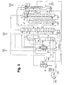
Figur 3- ein weiteres Ausführungsbeispiel mit Mitteldruckturbine,
Figur 4- ein viertes Ausführungsbeispiel mit Niederdruckturbine und
Figur 5- eine weitere Variante mit einer Turbine zwischen Hochdrucksäule und Niederdrucksäule.
- FIG. 1
- a first embodiment of the invention,
- FIG. 2
- a modification with barriers in the high pressure column,
- FIG. 3
- another embodiment with medium-pressure turbine,
- FIG. 4
- a fourth embodiment with low-pressure turbine and
- FIG. 5
- Another variant with a turbine between high pressure column and low pressure column.
Über Leitung 1 von Figur 1 strömt gereinigte und auf etwa Taupunkt abgekühlte Luft gasförmig in die Hochdrucksäule 2 eines Rektifiziersystems zur Stickstoff-Sauerstoff-Trennung ein, das außerdem eine Niederdrucksäule 3 und einen Hauptkondensator 4 aufweist, der in dem Beispiel als Fallfilmverdampfer ausgebildet ist. Gasförmiger Stickstoff 5 vom Kopf der Hochdrucksäule wird zu einem ersten Teil 6 dem Kondensationsraum des Hauptkondensators 4 zugeleitet. Das dort gebildete Kondensat 7 wird zu einem ersten Teil 8 der Hochdrucksäule als Rücklauf aufgegeben. Ein zweiter Teil 9 wird in einem Unterkühlungs-Gegenströmer 10 unterkühlt und über Leitung 11 und Drosselventil 12 der Niederdrucksäule 3 am Kopf zugeführt. Ein Teil 92 dieser Flüssigkeit kann als flüssiges Stickstoffprodukt (LIN) gewonnen werden.Via
Die sauerstoffangereicherte Sumpfflüssigkeit 13 der Hochdrucksäule 2 wird ebenfalls im Unterkühlungs-Gegenströmer 10 abgekühlt. Die unterkühlte sauerstoffangereicherte Flüssigkeit 14 wird in zwei Teilströmen weitergeführt. Der erste Teilstrom 15 - 16 wird als "krypton- und xenonhaltige Fraktion" in den Verdampfungsraum eines "ersten Kondensator-Verdampfers" 17 eingeleitet, der den Kopfkondensator einer Rohargonrektifikation 18/19 darstellt. Ein zweiter Teilstrom 15 - 20 wird in den Verdampfungsraum eines Kopfkondensators 21 einer Reinargonsäule 22 eingespeist.The oxygen-enriched bottoms liquid 13 of the high-
Der erste Kondensator-Verdampfer 17 ist als Umlaufverdampfer ausgebildet, das heißt der Verdampfungsraum enthält ein Flüssigkeitsbad, in das ein Wärmetauscherblock zum Beispiel teilweise eingetaucht ist. (Vorzugsweise ist der Wärmetauscherblockabweichend von der zeichnerischen Darstellung - vollständig in das Flüssigkeitsbad eingetaucht.) Flüssigkeit wird durch den Thermosiphon-Effekt am unteren Ende der Verdampfungspassagen angesaugt. An deren oberem Ende tritt ein Gemisch aus Dampf und unverdampfter Flüssigkeit aus, wobei letztere in das Flüssigkeitsbad zurückströmt. Im ersten Kondensator-Verdampfer 17 wird die krypton- und xenonhaltige Fraktion 16 partiell verdampft; beispielsweise 0,5 bis 10 mol%, vorzugsweise 1 bis 5 mol% der eingeführten Flüssigkeit 16 werden flüssig als Spülflüssigkeit 26 aus dem Verdampfungsraum des ersten Kondensator-Verdampfers 17 abgezogen. Durch diese partielle Verdampfung wird die Konzentration von schwererflüchtigen Komponenten, insbesondere von Krypton und Xenon, in der Flüssigkeit erhöht und im Dampf vermindert (jeweils im Vergleich zur Zusammensetzung der krypton- und xenonhaltigen Fraktion 16). Der bei der partiellen Verdampfung erzeugte Dampf wird als gasförmiger Strom 25 aus dem Verdampfungsraum des ersten Kondensator-Verdampfers 17 abgezogen. Verbleibende Flüssigkeit wird als "Spülflüssigkeit" 26 aus dem Flüssigkeitsbad abgeführt und der Krypton-Xenon-Anreicherungssäule 24 unmittelbar oberhalb des Sumpfs zugeleitet.The first condenser-
Die Krypton-Xenon-Anreicherungssäule 24 weist einen Sumpfverdampfer ("zweiter Kondensator Verdampfer") 27 auf, der mit jeder geeigneten Fraktion beheizt werden kann. In dem Ausführungsbeispiel wird Druckstickstoff 28 vom Kopf der Hochdrucksäule 2 als Heizmittel verwendet. (Alternativ dazu könnte jede andere Fraktion aus der Hochdrucksäule, ein Teilstrom der Einsatzluft oder ein Teil des Rohargons 50 vom Kopf der zweiten Rohargonsäule 19 eingesetzt werden.) Der in dem Sumpfverdampfer 27 verflüssigte Stickstoff 29 wird mit der Flüssigkeit 7 aus dem Hauptkondensator 4 vermischt. Als Rücklaufflüssigkeit wird ein Teilstrom 23 der Spülflüssigkeit aus dem Verdampfer des Kopfkondensators 21 der Reinargonsäule 22 auf den Kopf der Krypton-Xenon-Anreicherungssäule 24 aufgegeben. Der aus dem Sumpfverdampfer 27 aufsteigende Dampf tritt in der Krypton-Xenon-Anreicherungssäule in Gegenstrom-Stoffaustausch mit der Flüssigkeit 23, die ärmer an Krypton und Xenon ist. Dadurch werden diese Komponenten in den Sumpf gewaschen, wogegen Methan zum größten Teil mit dem Kopfgas 30 ausgeschleust wird. Letzteres wird in dem Ausführungsbeispiel der Niederdrucksäule 3 an einer geeigneten Zwischenstelle zugespeist. Vom Sumpf der Krypton-Xenon-Anreicherungssäule 24 wird ein Krypton-Xenon-Konzentrat 30 in flüssiger Form entnommen (LOX/Kr/Xe), das beispielsweise einen Krypton-Gehalt von etwa 2400 ppm und einen Xenon-Gehalt von etwa 200 ppm enthält: Im Übrigen besteht das Konzentrat 30 hauptsächlich aus Sauerstoff und enthält noch etwa 10 mol% Stickstoff. Das Konzentrat 30 kann in einem Flüssigtank gespeichert oder direkt einer Weiterverarbeitung zur Gewinnung von reinem Krypton und/oder Xenon zugeführt werden.The krypton-
Von der Niederdrucksäule 3 werden neben dem Flüssigstickstoff 92 reiner gasförmiger Stickstoff 32 am Kopf, Unreinstickstoff 33 ebenfalls in Gasform sowie Sauerstoff 34 in flüssiger Form mindestens teilweise als Produkte abgezogen. Die gasförmigen Produkte 32, 33 werden im Unterkühlungs-Gegenströmer 10 und weiter in einem nicht dargestellten Hauptwärmetauscher angewärmt. Der flüssige Sauerstoff 34 wird in insgesamt drei Teile aufgeteilt. Ein erster und ein zweiter Teil werden zunächst gemeinsam über Leitung 35 und Pumpe 36 gefördert. Der erste Teil 37 strömt zum Verdampfungsraum des Hauptkondensators 4 und wird dort teilweise verdampft. Das dabei gebildete Dampf-Flüssigkeitsgemisch 38 fließt zum Sumpf der Niederdrucksäule 3 zurück. Über die Leitungen 39 und 40 wird der zweite Teil als Flüssigprodukt (LOX) abgezogen, gegebenenfalls nach Unterkühlung im Unterkühlungs-Gegenströmer 10.From the low-
Der dritte Teil 41 des flüssigen Sauerstoffs 34 vom Sumpf der Niederdrucksäule 3 wird einer Innenverdichtung (internal compression) unterzogen, indem er in einer Pumpe 42 auf den gewünschten Produktdruck gebracht und über Leitung 43 (LOX - IC) einem oder mehreren Wärmetauschern zugeführt wird, in dem oder denen er verdampft (beziehungsweise - bei überkritischem Produktdruck - pseudo-verdampft) und auf etwa Umgebungstemperatur angewärmt wird. Verdampfung und Anwärmung können beispielsweise in indirektem Wärmeaustausch mit einem Hochdruckluftstrom durchgeführt werden. Die dabei verflüssigte (oder überkritische) Hochdruckluft wird entspannt (nicht dargestellt) und als Flüssigluft 44 der Hochdrucksäule 2 an einer "ersten Zwischenstelle" zugeleitet. Von einer "zweiten Zwischenstelle", die unmittelbar oberhalb dieser ersten Zwischenstelle angeordnet ist, wird eine sauerstoffhaltige Flüssigkeit 45 aus der Hochdrucksäule abgezogen, deren Menge mindestens einem Teil der Flüssigluft 44 entspricht; der Strom 45 kann auch größer als der Strom 44 sein. Zwischen der ersten und der zweiten Zwischenstelle befinden sich keine Böden oder sonstigen Stoffaustauschelemente. Die sauerstoffhaltige Flüssigkeit 45, deren Zusammensetzung weitgehend der Luft entspricht, wird nach Unterkühlung im Unterkühlungs-Gegenströmer 10 über Leitung 46 und Drosselventil 47 in die Niederdrucksäule 3 eingespeist.The
Über eine Argonübergangs-Leitung 48 wird eine argonhaltige Fraktion aus der Niederdrucksäule 3 in eine Rohargonrektifikation geleitet, die in dem Beispiel in zwei seriell verbundenen Rohargonsäulen 18 und 19 durchgeführt wird. Die argonhaltige Fraktion 48 wird der ersten Rohargonsäule 18 ummittelbar über dem Sumpf gasförmig zugeleitet. Der aufsteigende Dampf reichert sich an Argon an. Das Kopfgas der ersten Rohargonsäule 18 strömt über Leitung 49 weiter zum Sumpf der zweiten Rohargonsäule 19.Via an
Am Kopf der zweiten Rohargonsäule 19 wird argonangereicherter Dampf (Rohargon) 50 erzeugt und in dem ersten Kondensator-Verdampfer 17 zum großen Teil kondensiert. Die dabei erzeugte Flüssigkeit 51 wird als Rücklaufflüssigkeit auf die zweite Rohargonsäule 19 aufgegeben. Die im Sumpf der zweiten Rohargonsäule 19 anfallende Flüssigkeit 52 wird mittels einer Pumpe 53 über Leitung 54 zum Kopf der ersten Rohargonsäule 18 gefördert. Sumpfflüssigkeit 55 der ersten Rohargonsäule 18 strömt über ein weitere Pumpe 56 und Leitung 57 in die Niederdrucksäule 3 zurück.Argon-enriched vapor (crude argon) 50 is generated at the top of the second
Gasförmig verbliebenen Rohargon 58 aus dem Verflüssigungsraum des ersten Kondensator-Verdampfers 17 wird in der Reinargonsäule weiter zerlegt, insbesondere von leichterflüchtigen Bestandteilen wie Stickstoff befreit. Reinargonprodukt (LAR) wird über die Leitungen 59 und 60 in flüssiger Form abgezogen. Ein anderer Teil 61 der Sumpfflüssigkeit wird in einem Reinargon-Verdampfer 63 mit angeschlossenem Abscheider 62 verdampft und über Leitung 64 als aufsteigender Dampf in die Reinargonsäule 22 zurückgeleitet. Der Reinargon-Verdampfer 63 wird durch indirekten Wärmeaustausch mit mindestens einem Teil der Sumpfflüssigkeit 15 der Hochdrucksäule 2 beheizt, die bei dem Wärmeaustausch unterkühlt wird. Der Kopfkondensator 21 der Reinargonsäule wird wie bereits beschrieben mit einem Teil 20 dieser unterkühlten Flüssigkeit gekühlt. Aus dem Verdampfungsraum des Kopfkondensators 21 werden Dampf 66 und verbliebene Flüssigkeit 23, 65 abgezogen und an geeigneten Zwischenstellen in die Niederdrucksäule 3 eingespeist beziehungsweise (23) auf die Krypton-Xenon-Anreicherungssäule 24 aufgegeben. Im Verflüssigungsraum kondensiert Kopfgas 67 der Reinargonsäule 22 partiell. Dabei erzeugte Rücklaufflüssigkeit 68 wird auf die Reinargonsäule aufgegeben. Restdampf 69 wird in die Atmosphäre abgeblasen.Gaseous remaining
In dem Ausführungsbeispiel der Figur 1 wird die gesamte sauerstoffangereicherte Flüssigkeit, die in der Hochdrucksäule 2 erzeugt wird, vom Sumpf abgezogen (Leitung 13). Auf diese Weise ist eine relativ unkomplizierte Bauweise der Hochdrucksäule 2 möglich. Figur 2 zeigt eine Abwandlung dieses Verfahrens, bei dem die Ausbeute an Krypton und Xenon weiter verbessert wird. Hier ist ein weiterer Zwischenabzug für Flüssigkeit 270 aus der Hochdrucksäule 2 vorgesehen, der durch etwa vier Sperrböden 271 vom Sumpfabzug 213 getrennt ist. Diese Böden halten den größten Teil der schwerflüchtigen Bestandteile, insbesondere Krypton und Xenon, im Sumpf der Hochdrucksäule 2 zurück. Der Strom 270 weist dadurch einen deutlich geringeren Krypton- und Xenon-Gehalt auf als die Sumpfflüssigkeit 213. Er wird über den Unterkühlungs-Gegenströmer 10 zum einen Teil 220 in den Verdampfungsraum des Kopfkondensators 21 der Reinargonsäule 22 geleitet. Der Rest 223 strömt zum Kopf der Krypton-Xenon-Anreicherungssäule 24. Damit ergibt sich sowohl in den aus dem Kopfkondensator 21 zur Niederdrucksäule 3 strömenden Fraktionen 265, 266 als auch in der Rücklaufflüssigkeit 223 eine besonders niedriger Krypton- und Xenon-Gehalt.In the embodiment of FIG. 1, all of the oxygen-enriched liquid produced in the
Beides führt zu einer besonders hohen Ausbeute bei der Krypton- und Xenongewinnung.Both lead to a particularly high yield in krypton and xenon production.
Ein Großteil (typischerweise etwa 90 mol%) des in der Luft enthaltenen Kryptons und Xenons strömt mit der Sumpfflüssigkeit 213 über den Unterkühlungs-Gegenströmer 10 und Leitung 215, den Reinargon-Verdampfer 63, die Leitung 216 und den ersten Kondensator-Verdampfer 17, sowie weiter über die Leitung 225 und 226 zur Krypton-Xenon-Anreicherungssäule 24 und wird dort praktisch vollständig mit dem Krypton-Xenon-Konzentrat 30 gewonnen.Much (typically about 90 mole%) of the cryptone and xenon contained in the air flows with the bottoms liquid 213 via the
Über die Bypass-Leitung 272 kann bei Bedarf ein Teil der Flüssigkeit 270 von dem Zwischenabzug zur Sumpfflüssigkeit 213 hinzugemischt werden. Zwischen diesem Zwischenabzug und der ersten Zwischenstelle, an der die Flüssigluft 44 aus der Innenverdichtung eingeleitet wird, befinden sich beispielsweise zwei bis 14, vorzugsweise etwa fünf bis acht theoretische Böden.If necessary, part of the liquid 270 can be mixed from the intermediate draw to the
Während bei den Figuren 1 und 2 die Kältegewinnung nicht dargestellt ist, unterscheidet sich das in Figur 3 gezeigte System durch die Kältegewinnung mittels einer Mitteldruckturbine von dem in Figur 1 skizzierten. Die Turbine selbst ist nicht dargestellt, sondern lediglich der von ihrem Austritt kommende Teilstrom 373, der als Zwei-Phasen-Gemisch vorliegt. Er wird in einen Abscheider (Phasentrenner) 274 eingeleitet. Der Dampf 375 aus dem Abscheider 374 wird wie üblich gemeinsam mit der Direktluft 1 in die Hochdrucksäule 2 eingespeist. Die Flüssigkeit 376, die einen erhöhten Gehalt an Krypton und Xenon aufweist, wird dagegen gemeinsam mit einem Teil der unterkühlten Sumpfflüssigkeit 14 der Hochdrucksäule 2 über Leitung 416 in den Verdampfungsraum des ersten Kondensator-Verdampfers 17 eingeleitet. Ein anderer Teil 323 der unterkühlten Sumpfflüssigkeit 14 wird auf den Kopf der Krypton-Xenon-Anreicherungssäule 24 aufgegeben. Selbstverständlich können die in Figur 3 dargestellten zusätzlichen Merkmale auch mit der Variante von Figur 2 kombiniert werden.While in the figures 1 and 2, the refrigeration is not shown, differs the system shown in Figure 3 by the refrigeration by means of a medium-pressure turbine of the sketched in Figure 1. The turbine itself is not shown, but only coming from its
In Figur 4 wird Verfahrenskälte mittels einer Niederdruckturbine erzeugt. Die vom Austritt dieser Turbine kommende Luft 477 steht unter etwa dem Betriebsdruck der Niederdrucksäule 3, wird aber hier nicht direkt in diese Säule geführt, sondern in eine Strippsäule 478 eingeleitet, in der die schwererflüchtigen Anteile in den Sumpf ausgewaschen werden. Die Sumpfflüssigkeit 479 wird dann auf der Krypton-Xenon-Anreicherungssäule 24 an einer geeigneten Zwischenstelle zugeführt. Sie bildet einen Teil der Rücklaufflüssigkeit für die Krypton-Xenon-Anreicherungssäule 24. Lediglich das Krypton- und Xenon-arme Kopfgas 480 der Strippsäule 478 fließt direkt in die Niederdrucksäule 3 und umgeht damit die Krypton-Xenon-Gewinnung. Auf den Kopf der Krypton-Xenon-Anreicherungssäule 24 und der Strippsäule 478 wird jeweils ein Teilstrom 423, 492 der unterkühlten Sumpfflüssigkeit 14 der Hochdrucksäule aufgegeben.In FIG. 4 , process refrigeration is produced by means of a low-pressure turbine. The coming of the exit of this
Hochdrucksäule 2, Niederdrucksäule 3 und Hauptkondensator 4 sind in Figur 5 vereinfacht als Doppelsäule dargestellt. Kälte wird hier durch arbeitsleistende Entspannung einer gasförmigen Zwischenfraktion 581 von einer Zwischenstelle oberhalb der Sperrböden 271. Diese Fraktion kann im Hauptwärmetauscher 582 gegen abzukühlende Einsatzluft 583 angewärmt, über Leitung 584 einem Nachverdichter 585 zugeführt und weiter zum warmen Ende des Hauptwärmetauschers 582 geleitet (586) werden. Bei einer Zwischentemperatur wird sie über Leitung 587 dem Hauptwärmetauscher 582 entnommen und der arbeitsleistenden Entspannung 588 zugeführt. Die Turbine 588 treibt vorzugsweise über eine direkte mechanische Kopplung den Nachverdichter 585 an. Der arbeitsleistend entspannte Strom wird schließlich an geeigneter Stelle in die Niederdrucksäule 3 eingeleitet (589). Alternativ kann auf die Nachverdichtung und die vollständige Anwärmung verzichtet werden, indem der Strom über die gestrichelt dargestellte Leitung 590 im Hauptwärmetauscher 582 lediglich bis zu der Eintrittstemperatur der Turbine 588 angewärmt und dieser dann direkt zugeführt wird (Leitung 587).High-
Die Argon- und die Krypton-/Xenongewinnung sind in Figur 5 nicht dargestellt. Sie werden analog zu Figur 1 oder 2 durchgeführt. Eine Innenverdichtung ist bei Figur 5 nicht vorgesehen.The argon and krypton / xenon recovery are not shown in Figure 5. They are carried out analogously to FIG. 1 or 2. An internal compression is not provided in Figure 5.
Claims (10)
- Process for producing krypton and/or xenon by low-temperature fractionation of air, in which• compressed and cleaned charge air (1) is introduced into a rectification system for nitrogen-oxygen separation which at least includes a high-pressure column (2) and a low-pressure column (3),• a krypton- and xenon-containing fraction (13, 14, 15, 16, 416) is removed from the high-pressure column (2),• the krypton- and xenon-containing fraction (13, 14, 15, 16, 416) is introduced into the evaporation space of a first condenser-evaporator (17), where it is partially evaporated,• a purge liquid (26, 226) is extracted from the evaporation space of the first condenser-evaporator (17), and• is fed to a krypton-xenon enrichment column (24), and• a krypton-xenon concentrate (30) is removed from the krypton-xenon enrichment column (24),characterized in that• a liquid from the lower region of the krypton-xenon enrichment column (24) is introduced into a second condenser-evaporator (27), which is separate from the first condenser-evaporator (17).
- Process according to Claim 1, characterized in that an argon-containing fraction (48) from the low-pressure column (2) is introduced into a crude argon rectification stage (18, 19), an argon-enriched vapour (50) from the crude argon rectification stage (18, 19) being brought into indirect heat exchange with the evaporating krypton- and xenon-containing fraction (16) in the first condenser-evaporator (17).
- Process according to Claim 1 or 2, characterized in that a part-stream (44) of the charge air is fed into the high-pressure column (2) in the liquid state at a first intermediate point, and an oxygen-containing liquid (45) is extracted from the high-pressure column (2) at a second intermediate point, which is arranged above this first intermediate point, and is introduced into the low-pressure column (3).
- Process according to Claim 3, characterized in that there are no mass transfer elements between the first intermediate point and the second intermediate point.
- Process according to one of Claims 1 to 4, characterized in that there are barrier plates (271) arranged in the high-pressure column (2), the krypton- and xenon-containing fraction (213) being extracted below the barrier plates (271) and an oxygen-enriched liquid (270) being removed above the barrier plates.
- Process according to one of Claims 1 to 5, characterized in that a gaseous stream (25, 225) is extracted from the evaporation space of the first condenser-evaporator (17) and is likewise fed to the krypton-xenon enrichment column (24).
- Process according to one of Claims 1 to 6, characterized in that a part-stream (373) of the charge air is expanded in a work-performing manner to approximately the operating pressure of the high-pressure column (2) and is then fed to a phase separation (374), and in that at least part of the liquid fraction (376) from the phase separation (374) is fed to the krypton-xenon enrichment column (24) or the evaporation space of the first condenser-evaporator (17).
- Process according to one of Claims 1 to 7, characterized in that a part-stream (477) of the charge air is expanded in a work-performing manner to approximately the operating pressure of the low-pressure column and is fed to a stripping column (478), the bottom liquid (479) from the stripping column (478) being fed to the krypton-xenon enrichment column (24).
- Apparatus for producing krypton and/or xenon by low-temperature fractionation of air, having• a charge-air line (1) for introducing compressed and precleaned charge air into a rectification system for nitrogen-oxygen separation which at least includes a high-pressure column (2) and a low-pressure column (3),• having a removal line (13, 14, 15, 16, 416) for removing a krypton- and xenon-containing fraction from the high-pressure column (2),• the removal line (13, 14, 15, 16, 416) for the krypton- and xenon-containing fraction being connected to the evaporation space of a first condenser-evaporator (17),• a purge-liquid line (26, 226) being connected to the evaporation space of the condenser-evaporator (17) and to a krypton-xenon enrichment column (24), and• the krypton-xenon enrichment column (24) having a product line (30) for a krypton-xenon concentrate,characterized by• a second condenser-evaporator (27), which is separate from the first condenser-evaporator (17) and the evaporation space of which is in flow communication with the lower region of the krypton-xenon enrichment column (24).
- Apparatus according to Claim 9, characterized in that the low-pressure column (2) is connected via an argon transfer line (48) to a crude argon rectification stage (18, 19), and the liquefaction space of the first condenser-evaporator (17) is in flow communication with the crude argon rectification stage (18, 19).
Priority Applications (1)
| Application Number | Priority Date | Filing Date | Title |
|---|---|---|---|
| EP02023333A EP1308680B1 (en) | 2001-10-31 | 2002-10-18 | Process and system for production of krypton and/or xenon by cryogenic air separation |
Applications Claiming Priority (5)
| Application Number | Priority Date | Filing Date | Title |
|---|---|---|---|
| DE10153252 | 2001-10-31 | ||
| DE10153252A DE10153252A1 (en) | 2001-10-31 | 2001-10-31 | Process for recovering krypton and/or xenon by low temperature decomposition of air, comprises passing compressed purified process air to a rectifier system, removing a fraction containing krypton and xenon, and further processing |
| EP02001356 | 2002-01-18 | ||
| EP02001356 | 2002-01-18 | ||
| EP02023333A EP1308680B1 (en) | 2001-10-31 | 2002-10-18 | Process and system for production of krypton and/or xenon by cryogenic air separation |
Publications (2)
| Publication Number | Publication Date |
|---|---|
| EP1308680A1 EP1308680A1 (en) | 2003-05-07 |
| EP1308680B1 true EP1308680B1 (en) | 2006-06-07 |
Family
ID=26010476
Family Applications (1)
| Application Number | Title | Priority Date | Filing Date |
|---|---|---|---|
| EP02023333A Expired - Lifetime EP1308680B1 (en) | 2001-10-31 | 2002-10-18 | Process and system for production of krypton and/or xenon by cryogenic air separation |
Country Status (10)
| Country | Link |
|---|---|
| US (1) | US6612129B2 (en) |
| EP (1) | EP1308680B1 (en) |
| JP (1) | JP4331460B2 (en) |
| KR (1) | KR100917954B1 (en) |
| CN (1) | CN100346119C (en) |
| AT (1) | ATE329218T1 (en) |
| DE (2) | DE10153252A1 (en) |
| ES (1) | ES2266381T3 (en) |
| PT (1) | PT1308680E (en) |
| TW (1) | TW587151B (en) |
Cited By (3)
| Publication number | Priority date | Publication date | Assignee | Title |
|---|---|---|---|---|
| DE102009014556A1 (en) | 2009-03-24 | 2010-09-30 | Linde Aktiengesellschaft | Process for heating a separation column |
| DE102009023087A1 (en) | 2009-04-28 | 2010-11-04 | Linde Ag | Enrichment of krypton and xenon in oxygen fraction of air liquefaction plant, employs plate heat exchanger block made from copper, nickel or their alloys |
| EP2312248A1 (en) | 2009-10-07 | 2011-04-20 | Linde Aktiengesellschaft | Method and device for obtaining pressurised oxygen and krypton/xenon |
Families Citing this family (32)
| Publication number | Priority date | Publication date | Assignee | Title |
|---|---|---|---|---|
| FR2844039B1 (en) * | 2002-09-04 | 2005-04-29 | Air Liquide | PROCESS AND PLANT FOR PRODUCING OXYGEN AND RARE GASES BY CRYOGENIC AIR DISTILLATION |
| US6694775B1 (en) | 2002-12-12 | 2004-02-24 | Air Products And Chemicals, Inc. | Process and apparatus for the recovery of krypton and/or xenon |
| DE10334560A1 (en) * | 2003-05-28 | 2004-12-16 | Linde Ag | Method for recovering krypton and xenon from air, comprises separating nitrogen and oxygen and feeding krypton- and xenon-containing fraction into enrichment column, stream of pure air being decompressed and fed into column |
| RU2300717C1 (en) * | 2005-12-29 | 2007-06-10 | Михаил Юрьевич Савинов | Method and device for krypton-xenon mixture separation by rectification thereof |
| EP1837614A1 (en) * | 2006-03-23 | 2007-09-26 | Linde Aktiengesellschaft | Process and device for the vaporisation of an oxygen enriched liquid and process and device for the cryogenic separation of air |
| RU2328336C2 (en) * | 2006-08-04 | 2008-07-10 | Михаил Юрьевич Савинов | Method and device for cleaning and separating concentrate of heavy target components with obtaining target components of concentrate and light elements isotopes |
| DE102007031765A1 (en) | 2007-07-07 | 2009-01-08 | Linde Ag | Process for the cryogenic separation of air |
| DE102007031759A1 (en) | 2007-07-07 | 2009-01-08 | Linde Ag | Method and apparatus for producing gaseous pressure product by cryogenic separation of air |
| US20100024478A1 (en) * | 2008-07-29 | 2010-02-04 | Horst Corduan | Process and device for recovering argon by low-temperature separation of air |
| US8443625B2 (en) | 2008-08-14 | 2013-05-21 | Praxair Technology, Inc. | Krypton and xenon recovery method |
| DE102009034979A1 (en) | 2009-04-28 | 2010-11-04 | Linde Aktiengesellschaft | Method for producing pressurized oxygen by evaporating liquid oxygen using a copper and nickel heat exchanger block |
| US8978413B2 (en) | 2010-06-09 | 2015-03-17 | L'air Liquide, Societe Anonyme Pour L'etude Et L'exploitation Des Procedes Georges Claude | Rare gases recovery process for triple column oxygen plant |
| DE102010052545A1 (en) | 2010-11-25 | 2012-05-31 | Linde Aktiengesellschaft | Method and apparatus for recovering a gaseous product by cryogenic separation of air |
| DE102010052544A1 (en) | 2010-11-25 | 2012-05-31 | Linde Ag | Process for obtaining a gaseous product by cryogenic separation of air |
| EP2520886A1 (en) | 2011-05-05 | 2012-11-07 | Linde AG | Method and device for creating gaseous oxygen pressurised product by the cryogenic decomposition of air |
| CN102359895B (en) * | 2011-08-15 | 2014-08-06 | 西北核技术研究所 | Normal temperature enrichment and sampling method for xenon in air |
| DE102011112909A1 (en) | 2011-09-08 | 2013-03-14 | Linde Aktiengesellschaft | Process and apparatus for recovering steel |
| EP2600090B1 (en) | 2011-12-01 | 2014-07-16 | Linde Aktiengesellschaft | Method and device for generating pressurised oxygen by cryogenic decomposition of air |
| DE102011121314A1 (en) | 2011-12-16 | 2013-06-20 | Linde Aktiengesellschaft | Method for producing gaseous oxygen product in main heat exchanger system in distillation column system, involves providing turbines, where one of turbines drives compressor, and other turbine drives generator |
| WO2013141761A2 (en) * | 2012-03-20 | 2013-09-26 | Bondarenko Vitaly Leonidovich | Assembly for separating gas mixtures in fractionating columns |
| DE102012017488A1 (en) | 2012-09-04 | 2014-03-06 | Linde Aktiengesellschaft | Method for building air separation plant, involves selecting air separation modules on basis of product specification of module set with different air pressure requirements |
| AU2014234685B2 (en) * | 2013-03-19 | 2019-04-18 | Linde Aktiengesellschaft | Method and device for generating gaseous compressed nitrogen. |
| WO2014154339A2 (en) | 2013-03-26 | 2014-10-02 | Linde Aktiengesellschaft | Method for air separation and air separation plant |
| EP2784420A1 (en) | 2013-03-26 | 2014-10-01 | Linde Aktiengesellschaft | Method for air separation and air separation plant |
| EP2801777A1 (en) | 2013-05-08 | 2014-11-12 | Linde Aktiengesellschaft | Air separation plant with main compressor drive |
| DE102013017590A1 (en) | 2013-10-22 | 2014-01-02 | Linde Aktiengesellschaft | Method for recovering methane-poor fluids in liquid air separation system to manufacture air product, involves vaporizing oxygen, krypton and xenon containing sump liquid in low pressure column by using multi-storey bath vaporizer |
| WO2015127648A1 (en) * | 2014-02-28 | 2015-09-03 | Praxair Technology, Inc. | Pressurized product stream delivery |
| EP2963367A1 (en) | 2014-07-05 | 2016-01-06 | Linde Aktiengesellschaft | Method and device for cryogenic air separation with variable power consumption |
| EP2963370B1 (en) | 2014-07-05 | 2018-06-13 | Linde Aktiengesellschaft | Method and device for the cryogenic decomposition of air |
| PL2963369T3 (en) | 2014-07-05 | 2018-10-31 | Linde Aktiengesellschaft | Method and device for the cryogenic decomposition of air |
| TR201808162T4 (en) | 2014-07-05 | 2018-07-23 | Linde Ag | Method and apparatus for recovering a pressurized gas product by decomposing air at low temperature. |
| CN115839601B (en) * | 2023-02-27 | 2023-05-12 | 中科富海(杭州)气体工程科技有限公司 | Liquid space division and krypton-xenon pre-concentration integrated equipment |
Family Cites Families (9)
| Publication number | Priority date | Publication date | Assignee | Title |
|---|---|---|---|---|
| DE2605305A1 (en) * | 1976-02-11 | 1977-08-18 | Messer Griesheim Gmbh | Separation of krypton and xenon from crude oxygen - by taking fraction from base of medium pressure column |
| US4401448A (en) * | 1982-05-24 | 1983-08-30 | Union Carbide Corporation | Air separation process for the production of krypton and xenon |
| US4568528A (en) * | 1984-08-16 | 1986-02-04 | Union Carbide Corporation | Process to produce a krypton-xenon concentrate and a gaseous oxygen product |
| DE3840506A1 (en) | 1988-12-01 | 1990-06-07 | Linde Ag | METHOD AND DEVICE FOR AIR DISASSEMBLY |
| US5067976A (en) * | 1991-02-05 | 1991-11-26 | Air Products And Chemicals, Inc. | Cryogenic process for the production of an oxygen-free and methane-free, krypton/xenon product |
| DE4317916A1 (en) | 1993-05-28 | 1994-12-01 | Linde Ag | Process and apparatus for the isolation of argon |
| DE19855487A1 (en) * | 1998-12-01 | 2000-06-08 | Linde Ag | Method and device for extracting pressurized oxygen and krypton / xenon by low-temperature separation of air |
| DE10000017A1 (en) * | 1999-11-22 | 2000-06-29 | Linde Ag | Process for recovery of krypton and/or xenon comprises removing oxygen-enriched fraction from the pressure column at an intermediate point |
| US6314757B1 (en) * | 2000-08-25 | 2001-11-13 | Prakair Technology, Inc. | Cryogenic rectification system for processing atmospheric fluids |
-
2001
- 2001-10-31 DE DE10153252A patent/DE10153252A1/en not_active Withdrawn
-
2002
- 2002-10-18 AT AT02023333T patent/ATE329218T1/en not_active IP Right Cessation
- 2002-10-18 EP EP02023333A patent/EP1308680B1/en not_active Expired - Lifetime
- 2002-10-18 PT PT02023333T patent/PT1308680E/en unknown
- 2002-10-18 ES ES02023333T patent/ES2266381T3/en not_active Expired - Lifetime
- 2002-10-18 DE DE50207089T patent/DE50207089D1/en not_active Expired - Lifetime
- 2002-10-24 TW TW091124677A patent/TW587151B/en not_active IP Right Cessation
- 2002-10-30 CN CNB02146975XA patent/CN100346119C/en not_active Expired - Fee Related
- 2002-10-30 KR KR1020020066388A patent/KR100917954B1/en not_active IP Right Cessation
- 2002-10-31 JP JP2002317667A patent/JP4331460B2/en not_active Expired - Fee Related
- 2002-10-31 US US10/284,479 patent/US6612129B2/en not_active Expired - Fee Related
Cited By (3)
| Publication number | Priority date | Publication date | Assignee | Title |
|---|---|---|---|---|
| DE102009014556A1 (en) | 2009-03-24 | 2010-09-30 | Linde Aktiengesellschaft | Process for heating a separation column |
| DE102009023087A1 (en) | 2009-04-28 | 2010-11-04 | Linde Ag | Enrichment of krypton and xenon in oxygen fraction of air liquefaction plant, employs plate heat exchanger block made from copper, nickel or their alloys |
| EP2312248A1 (en) | 2009-10-07 | 2011-04-20 | Linde Aktiengesellschaft | Method and device for obtaining pressurised oxygen and krypton/xenon |
Also Published As
| Publication number | Publication date |
|---|---|
| KR20030036029A (en) | 2003-05-09 |
| PT1308680E (en) | 2006-10-31 |
| US20030110795A1 (en) | 2003-06-19 |
| ATE329218T1 (en) | 2006-06-15 |
| JP2003165712A (en) | 2003-06-10 |
| CN100346119C (en) | 2007-10-31 |
| DE10153252A1 (en) | 2003-05-15 |
| US6612129B2 (en) | 2003-09-02 |
| TW587151B (en) | 2004-05-11 |
| KR100917954B1 (en) | 2009-09-21 |
| ES2266381T3 (en) | 2007-03-01 |
| JP4331460B2 (en) | 2009-09-16 |
| CN1419097A (en) | 2003-05-21 |
| DE50207089D1 (en) | 2006-07-20 |
| EP1308680A1 (en) | 2003-05-07 |
Similar Documents
| Publication | Publication Date | Title |
|---|---|---|
| EP1308680B1 (en) | Process and system for production of krypton and/or xenon by cryogenic air separation | |
| EP2235460B1 (en) | Process and device for the cryogenic separation of air | |
| EP1243882B1 (en) | Production of argon using a triple pressure air separation system with an argon column | |
| EP1482266B1 (en) | Process and device for the recovery of Krypton and/or Xenon by cryogenic separation of air | |
| EP1134525B1 (en) | Process for producing gaseous and liquid nitrogen with a variable quantity of liquid | |
| EP0716280B1 (en) | Method and apparatus for the low temperature air separation | |
| EP1284404A1 (en) | Process and device for recovering a product under pressure by cryogenic air separation | |
| EP1357342A1 (en) | Cryogenic triple column air separation system with argon recovery | |
| DE10332863A1 (en) | Krypton and xenon recovery by low-temperature fractionation of air yields higher purity products and higher argon productivity, using low nitrogen content scrubbing liquid stream | |
| EP2236964A1 (en) | Method and device for low-temperature air separation | |
| DE10334559A1 (en) | Process for recovering krypton/xenon by the cryogenic separation of air comprises feeding an argon-enriched vapor from a crude argon rectification system into a sump evaporator | |
| WO2020169257A1 (en) | Method and system for low-temperature air separation | |
| EP3290843A2 (en) | Method and device for extracting pressurised nitrogen and pressurised nitrogen by cryogenic decomposition of air | |
| EP0669508A1 (en) | Process and apparatus for obtaining pure argon | |
| EP1006326B1 (en) | Process and apparatus for the production of pressurised oxygen and krypton/xenon by cryogenic air separation | |
| DE60007686T2 (en) | Low temperature rectification system for air separation | |
| EP3394536A1 (en) | Method and device for obtaining pure nitrogen and pure oxygen by low-temperature separation of air | |
| EP3980705A1 (en) | Method and system for low-temperature air separation | |
| DE10232430A1 (en) | Process for recovering krypton and/or xenon comprises feeding a liquid from the lower region of a krypton-xenon enriching column to a condenser-vaporizer, and contacting an argon-enriched vapor with the liquid from the enriching column | |
| EP2914913A2 (en) | Process for the low-temperature separation of air in an air separation plant and air separation plant | |
| DE20319823U1 (en) | Device for extracting krypton and / or xenon by cryogenic decomposition | |
| WO2020187449A1 (en) | Method and system for low-temperature air separation | |
| EP1189001A1 (en) | Process and apparatus for the production of high purity nitrogen through cryogenic air separation | |
| DE10013074A1 (en) | Process for recovering gaseous nitrogen by the decomposition of air in a distillation column system comprises removing an oxygen-enriched gas from a condenser-vaporizer, relieving the pressure and heating in a heat exchanger | |
| DE19819263C2 (en) | Process and device for the production of pressurized nitrogen |
Legal Events
| Date | Code | Title | Description |
|---|---|---|---|
| PUAI | Public reference made under article 153(3) epc to a published international application that has entered the european phase |
Free format text: ORIGINAL CODE: 0009012 |
|
| AK | Designated contracting states |
Designated state(s): AT BE BG CH CY CZ DE DK EE ES FI FR GB GR IE IT LI LU MC NL PT SE SK TR |
|
| AX | Request for extension of the european patent |
Extension state: AL LT LV MK RO SI |
|
| 17P | Request for examination filed |
Effective date: 20031010 |
|
| AKX | Designation fees paid |
Designated state(s): AT BE BG CH CY CZ DE DK EE ES FI FR GB GR IE IT LI LU MC NL PT SE SK TR |
|
| GRAP | Despatch of communication of intention to grant a patent |
Free format text: ORIGINAL CODE: EPIDOSNIGR1 |
|
| GRAS | Grant fee paid |
Free format text: ORIGINAL CODE: EPIDOSNIGR3 |
|
| GRAA | (expected) grant |
Free format text: ORIGINAL CODE: 0009210 |
|
| AK | Designated contracting states |
Kind code of ref document: B1 Designated state(s): AT BE BG CH CY CZ DE DK EE ES FI FR GB GR IE IT LI LU MC NL PT SE SK TR |
|
| PG25 | Lapsed in a contracting state [announced via postgrant information from national office to epo] |
Ref country code: IT Free format text: LAPSE BECAUSE OF FAILURE TO SUBMIT A TRANSLATION OF THE DESCRIPTION OR TO PAY THE FEE WITHIN THE PRESCRIBED TIME-LIMIT;WARNING: LAPSES OF ITALIAN PATENTS WITH EFFECTIVE DATE BEFORE 2007 MAY HAVE OCCURRED AT ANY TIME BEFORE 2007. THE CORRECT EFFECTIVE DATE MAY BE DIFFERENT FROM THE ONE RECORDED. Effective date: 20060607 Ref country code: IE Free format text: LAPSE BECAUSE OF FAILURE TO SUBMIT A TRANSLATION OF THE DESCRIPTION OR TO PAY THE FEE WITHIN THE PRESCRIBED TIME-LIMIT Effective date: 20060607 |
|
| REG | Reference to a national code |
Ref country code: GB Ref legal event code: FG4D Free format text: NOT ENGLISH |
|
| REG | Reference to a national code |
Ref country code: CH Ref legal event code: EP |
|
| REG | Reference to a national code |
Ref country code: IE Ref legal event code: FG4D Free format text: LANGUAGE OF EP DOCUMENT: GERMAN |
|
| REF | Corresponds to: |
Ref document number: 50207089 Country of ref document: DE Date of ref document: 20060720 Kind code of ref document: P |
|
| PG25 | Lapsed in a contracting state [announced via postgrant information from national office to epo] |
Ref country code: DK Free format text: LAPSE BECAUSE OF FAILURE TO SUBMIT A TRANSLATION OF THE DESCRIPTION OR TO PAY THE FEE WITHIN THE PRESCRIBED TIME-LIMIT Effective date: 20060907 |
|
| REG | Reference to a national code |
Ref country code: SE Ref legal event code: TRGR |
|
| GBT | Gb: translation of ep patent filed (gb section 77(6)(a)/1977) |
Effective date: 20060913 |
|
| PG25 | Lapsed in a contracting state [announced via postgrant information from national office to epo] |
Ref country code: CH Free format text: LAPSE BECAUSE OF NON-PAYMENT OF DUE FEES Effective date: 20061031 Ref country code: MC Free format text: LAPSE BECAUSE OF NON-PAYMENT OF DUE FEES Effective date: 20061031 Ref country code: LI Free format text: LAPSE BECAUSE OF NON-PAYMENT OF DUE FEES Effective date: 20061031 |
|
| REG | Reference to a national code |
Ref country code: PT Ref legal event code: SC4A Effective date: 20060906 |
|
| REG | Reference to a national code |
Ref country code: IE Ref legal event code: FD4D |
|
| ET | Fr: translation filed | ||
| REG | Reference to a national code |
Ref country code: ES Ref legal event code: FG2A Ref document number: 2266381 Country of ref document: ES Kind code of ref document: T3 |
|
| PLBE | No opposition filed within time limit |
Free format text: ORIGINAL CODE: 0009261 |
|
| STAA | Information on the status of an ep patent application or granted ep patent |
Free format text: STATUS: NO OPPOSITION FILED WITHIN TIME LIMIT |
|
| 26N | No opposition filed |
Effective date: 20070308 |
|
| REG | Reference to a national code |
Ref country code: CH Ref legal event code: PL |
|
| BECA | Be: change of holder's address |
Owner name: *LINDE A.G.LEOPOLDSTRASSE 252, D-80807 MUENCHEN Effective date: 20060607 |
|
| REG | Reference to a national code |
Ref country code: PT Ref legal event code: TE4A Owner name: LINDE AG, DE Effective date: 20080104 |
|
| PG25 | Lapsed in a contracting state [announced via postgrant information from national office to epo] |
Ref country code: GR Free format text: LAPSE BECAUSE OF FAILURE TO SUBMIT A TRANSLATION OF THE DESCRIPTION OR TO PAY THE FEE WITHIN THE PRESCRIBED TIME-LIMIT Effective date: 20060908 |
|
| PG25 | Lapsed in a contracting state [announced via postgrant information from national office to epo] |
Ref country code: EE Free format text: LAPSE BECAUSE OF FAILURE TO SUBMIT A TRANSLATION OF THE DESCRIPTION OR TO PAY THE FEE WITHIN THE PRESCRIBED TIME-LIMIT Effective date: 20060607 |
|
| PG25 | Lapsed in a contracting state [announced via postgrant information from national office to epo] |
Ref country code: LU Free format text: LAPSE BECAUSE OF NON-PAYMENT OF DUE FEES Effective date: 20061018 |
|
| REG | Reference to a national code |
Ref country code: FR Ref legal event code: CA |
|
| PG25 | Lapsed in a contracting state [announced via postgrant information from national office to epo] |
Ref country code: CY Free format text: LAPSE BECAUSE OF FAILURE TO SUBMIT A TRANSLATION OF THE DESCRIPTION OR TO PAY THE FEE WITHIN THE PRESCRIBED TIME-LIMIT Effective date: 20060607 |
|
| PGFP | Annual fee paid to national office [announced via postgrant information from national office to epo] |
Ref country code: SK Payment date: 20090925 Year of fee payment: 8 |
|
| PGFP | Annual fee paid to national office [announced via postgrant information from national office to epo] |
Ref country code: AT Payment date: 20091013 Year of fee payment: 8 Ref country code: CZ Payment date: 20091006 Year of fee payment: 8 Ref country code: DE Payment date: 20091015 Year of fee payment: 8 Ref country code: ES Payment date: 20091117 Year of fee payment: 8 Ref country code: FI Payment date: 20091014 Year of fee payment: 8 Ref country code: SE Payment date: 20091007 Year of fee payment: 8 |
|
| PGFP | Annual fee paid to national office [announced via postgrant information from national office to epo] |
Ref country code: NL Payment date: 20091004 Year of fee payment: 8 |
|
| PGFP | Annual fee paid to national office [announced via postgrant information from national office to epo] |
Ref country code: PT Payment date: 20091019 Year of fee payment: 8 Ref country code: BG Payment date: 20091019 Year of fee payment: 8 |
|
| PGFP | Annual fee paid to national office [announced via postgrant information from national office to epo] |
Ref country code: FR Payment date: 20091029 Year of fee payment: 8 Ref country code: GB Payment date: 20091014 Year of fee payment: 8 Ref country code: IT Payment date: 20091017 Year of fee payment: 8 |
|
| PGFP | Annual fee paid to national office [announced via postgrant information from national office to epo] |
Ref country code: BE Payment date: 20091019 Year of fee payment: 8 |
|
| BERE | Be: lapsed |
Owner name: *LINDE A.G. Effective date: 20101031 |
|
| REG | Reference to a national code |
Ref country code: NL Ref legal event code: V1 Effective date: 20110501 |
|
| GBPC | Gb: european patent ceased through non-payment of renewal fee |
Effective date: 20101018 |
|
| REG | Reference to a national code |
Ref country code: SK Ref legal event code: MM4A Ref document number: E 960 Country of ref document: SK Effective date: 20101018 |
|
| PG25 | Lapsed in a contracting state [announced via postgrant information from national office to epo] |
Ref country code: FR Free format text: LAPSE BECAUSE OF NON-PAYMENT OF DUE FEES Effective date: 20101102 Ref country code: PT Free format text: LAPSE BECAUSE OF NON-PAYMENT OF DUE FEES Effective date: 20110418 Ref country code: CZ Free format text: LAPSE BECAUSE OF NON-PAYMENT OF DUE FEES Effective date: 20101018 |
|
| REG | Reference to a national code |
Ref country code: FR Ref legal event code: ST Effective date: 20110630 |
|
| PG25 | Lapsed in a contracting state [announced via postgrant information from national office to epo] |
Ref country code: AT Free format text: LAPSE BECAUSE OF NON-PAYMENT OF DUE FEES Effective date: 20101018 Ref country code: NL Free format text: LAPSE BECAUSE OF NON-PAYMENT OF DUE FEES Effective date: 20110501 Ref country code: GB Free format text: LAPSE BECAUSE OF NON-PAYMENT OF DUE FEES Effective date: 20101018 Ref country code: BG Free format text: LAPSE BECAUSE OF NON-PAYMENT OF DUE FEES Effective date: 20110531 Ref country code: BE Free format text: LAPSE BECAUSE OF NON-PAYMENT OF DUE FEES Effective date: 20101031 Ref country code: FI Free format text: LAPSE BECAUSE OF NON-PAYMENT OF DUE FEES Effective date: 20101018 Ref country code: SK Free format text: LAPSE BECAUSE OF NON-PAYMENT OF DUE FEES Effective date: 20101018 |
|
| REG | Reference to a national code |
Ref country code: DE Ref legal event code: R119 Ref document number: 50207089 Country of ref document: DE Effective date: 20110502 |
|
| PG25 | Lapsed in a contracting state [announced via postgrant information from national office to epo] |
Ref country code: SE Free format text: LAPSE BECAUSE OF NON-PAYMENT OF DUE FEES Effective date: 20101019 Ref country code: TR Free format text: LAPSE BECAUSE OF NON-PAYMENT OF DUE FEES Effective date: 20110726 |
|
| PGFP | Annual fee paid to national office [announced via postgrant information from national office to epo] |
Ref country code: TR Payment date: 20090924 Year of fee payment: 8 |
|
| REG | Reference to a national code |
Ref country code: ES Ref legal event code: FD2A Effective date: 20111118 |
|
| PG25 | Lapsed in a contracting state [announced via postgrant information from national office to epo] |
Ref country code: IT Free format text: LAPSE BECAUSE OF NON-PAYMENT OF DUE FEES Effective date: 20101018 |
|
| PG25 | Lapsed in a contracting state [announced via postgrant information from national office to epo] |
Ref country code: ES Free format text: LAPSE BECAUSE OF NON-PAYMENT OF DUE FEES Effective date: 20101019 |
|
| PG25 | Lapsed in a contracting state [announced via postgrant information from national office to epo] |
Ref country code: DE Free format text: LAPSE BECAUSE OF NON-PAYMENT OF DUE FEES Effective date: 20110502 |
|
| PG25 | Lapsed in a contracting state [announced via postgrant information from national office to epo] |
Ref country code: BG Free format text: LAPSE BECAUSE OF NON-PAYMENT OF DUE FEES Effective date: 20110630 |