EP1308525A2 - Procédé pour contrôler le durcissement par faisceau laser et dispositif pour durcir par faisceau laser - Google Patents
Procédé pour contrôler le durcissement par faisceau laser et dispositif pour durcir par faisceau laser Download PDFInfo
- Publication number
- EP1308525A2 EP1308525A2 EP02023451A EP02023451A EP1308525A2 EP 1308525 A2 EP1308525 A2 EP 1308525A2 EP 02023451 A EP02023451 A EP 02023451A EP 02023451 A EP02023451 A EP 02023451A EP 1308525 A2 EP1308525 A2 EP 1308525A2
- Authority
- EP
- European Patent Office
- Prior art keywords
- laser beam
- hardening
- workpiece
- temperature
- hardened
- Prior art date
- Legal status (The legal status is an assumption and is not a legal conclusion. Google has not performed a legal analysis and makes no representation as to the accuracy of the status listed.)
- Ceased
Links
Images


Classifications
-
- C—CHEMISTRY; METALLURGY
- C21—METALLURGY OF IRON
- C21D—MODIFYING THE PHYSICAL STRUCTURE OF FERROUS METALS; GENERAL DEVICES FOR HEAT TREATMENT OF FERROUS OR NON-FERROUS METALS OR ALLOYS; MAKING METAL MALLEABLE, e.g. BY DECARBURISATION OR TEMPERING
- C21D1/00—General methods or devices for heat treatment, e.g. annealing, hardening, quenching or tempering
- C21D1/06—Surface hardening
- C21D1/09—Surface hardening by direct application of electrical or wave energy; by particle radiation
-
- B—PERFORMING OPERATIONS; TRANSPORTING
- B23—MACHINE TOOLS; METAL-WORKING NOT OTHERWISE PROVIDED FOR
- B23K—SOLDERING OR UNSOLDERING; WELDING; CLADDING OR PLATING BY SOLDERING OR WELDING; CUTTING BY APPLYING HEAT LOCALLY, e.g. FLAME CUTTING; WORKING BY LASER BEAM
- B23K26/00—Working by laser beam, e.g. welding, cutting or boring
- B23K26/02—Positioning or observing the workpiece, e.g. with respect to the point of impact; Aligning, aiming or focusing the laser beam
- B23K26/06—Shaping the laser beam, e.g. by masks or multi-focusing
- B23K26/062—Shaping the laser beam, e.g. by masks or multi-focusing by direct control of the laser beam
- B23K26/0626—Energy control of the laser beam
-
- B—PERFORMING OPERATIONS; TRANSPORTING
- B23—MACHINE TOOLS; METAL-WORKING NOT OTHERWISE PROVIDED FOR
- B23K—SOLDERING OR UNSOLDERING; WELDING; CLADDING OR PLATING BY SOLDERING OR WELDING; CUTTING BY APPLYING HEAT LOCALLY, e.g. FLAME CUTTING; WORKING BY LASER BEAM
- B23K26/00—Working by laser beam, e.g. welding, cutting or boring
- B23K26/08—Devices involving relative movement between laser beam and workpiece
- B23K26/082—Scanning systems, i.e. devices involving movement of the laser beam relative to the laser head
-
- B—PERFORMING OPERATIONS; TRANSPORTING
- B23—MACHINE TOOLS; METAL-WORKING NOT OTHERWISE PROVIDED FOR
- B23K—SOLDERING OR UNSOLDERING; WELDING; CLADDING OR PLATING BY SOLDERING OR WELDING; CUTTING BY APPLYING HEAT LOCALLY, e.g. FLAME CUTTING; WORKING BY LASER BEAM
- B23K26/00—Working by laser beam, e.g. welding, cutting or boring
- B23K26/08—Devices involving relative movement between laser beam and workpiece
- B23K26/083—Devices involving movement of the workpiece in at least one axial direction
- B23K26/0838—Devices involving movement of the workpiece in at least one axial direction by using an endless conveyor belt
- B23K26/0846—Devices involving movement of the workpiece in at least one axial direction by using an endless conveyor belt for moving elongated workpieces longitudinally, e.g. wire or strip material
-
- B—PERFORMING OPERATIONS; TRANSPORTING
- B23—MACHINE TOOLS; METAL-WORKING NOT OTHERWISE PROVIDED FOR
- B23K—SOLDERING OR UNSOLDERING; WELDING; CLADDING OR PLATING BY SOLDERING OR WELDING; CUTTING BY APPLYING HEAT LOCALLY, e.g. FLAME CUTTING; WORKING BY LASER BEAM
- B23K26/00—Working by laser beam, e.g. welding, cutting or boring
- B23K26/352—Working by laser beam, e.g. welding, cutting or boring for surface treatment
-
- B—PERFORMING OPERATIONS; TRANSPORTING
- B23—MACHINE TOOLS; METAL-WORKING NOT OTHERWISE PROVIDED FOR
- B23K—SOLDERING OR UNSOLDERING; WELDING; CLADDING OR PLATING BY SOLDERING OR WELDING; CUTTING BY APPLYING HEAT LOCALLY, e.g. FLAME CUTTING; WORKING BY LASER BEAM
- B23K26/00—Working by laser beam, e.g. welding, cutting or boring
- B23K26/70—Auxiliary operations or equipment
- B23K26/702—Auxiliary equipment
- B23K26/705—Beam measuring device
-
- B—PERFORMING OPERATIONS; TRANSPORTING
- B23—MACHINE TOOLS; METAL-WORKING NOT OTHERWISE PROVIDED FOR
- B23K—SOLDERING OR UNSOLDERING; WELDING; CLADDING OR PLATING BY SOLDERING OR WELDING; CUTTING BY APPLYING HEAT LOCALLY, e.g. FLAME CUTTING; WORKING BY LASER BEAM
- B23K26/00—Working by laser beam, e.g. welding, cutting or boring
- B23K26/70—Auxiliary operations or equipment
- B23K26/702—Auxiliary equipment
- B23K26/707—Auxiliary equipment for monitoring laser beam transmission optics
-
- C—CHEMISTRY; METALLURGY
- C21—METALLURGY OF IRON
- C21D—MODIFYING THE PHYSICAL STRUCTURE OF FERROUS METALS; GENERAL DEVICES FOR HEAT TREATMENT OF FERROUS OR NON-FERROUS METALS OR ALLOYS; MAKING METAL MALLEABLE, e.g. BY DECARBURISATION OR TEMPERING
- C21D11/00—Process control or regulation for heat treatments
Definitions
- a method of hardening on a workpiece with a predetermined width by oscillating laser beam in a direction intersecting a feeding direction has been recently proposed. But, it is necessary to correctly detect the temperature of a portion to be hardened and to control the temperature of the portion for proper hardening.
- the moving velocity of the laser beam for hardening with respect to a workpiece always changes although a workpiece can be hardened with an optional width. If a constant output of the laser beam is only irradiated on a workpiece, therefore, the radiation energy per unit area in the portion to be hardened of a workpiece is too high in the position where the relative velocity of the laser beam with respect to the workpiece is decreased so as to melt the workpiece.
- the laser beam hardening device capable of correctly measuring the temperature of a portion to be hardened even if a torch takes a complicated action as mentioned before, and controlling the temperature of the portion is desired to be provided.
- the present invention is method of controlling hardening with laser beam by irradiating laser beam on a workpiece, comprising:
- the laser beam output in the both end portions (times (1), (5), (6), (10) of Fig.4, for instance) of the amplitude of the laser beam is made lower than one of a center portion (times (3), (4), (7), (8) of Fig.4, for instance) of the amplitude, thereby the relative moving velocity of the laser beam with respect to the workpiece is decreased and the quantity of giving energy of the laser beam in both end portions of the amplitude where the density of giving energy is high can be decreased so as to equalize quantity of aiming energy in the whole hardening cycle. By doing so, a proper hardening action is possible.
- the present invention is that said hardening temperature of said workpiece is measured by acquiring reflecting light of said laser beam irradiating on said workpiece.
- the hardening temperature of a workpiece is measured by acquiring the reflecting light of the laser beam irradiating on the workpiece, thereby the temperature of the portion to be hardened is correctly gotten, and a proper hardening is possible.
- the present invention is that a laser beam output pattern corresponding to a hardening action is prepared, and said laser beam output of said laser beam is controlled in such a manner that said laser beam output in both end portions of said amplitude is made lower than one of said center portion of said amplitude on the basis of said laser beam output pattern.
- a temperature of a portion to be hardened of the workpiece is detected at some point of time (time (1) of cycle 0 of hardening cycle of Fig.4, for instance) during the hardening cycle and the laser beam output of the laser beam is adjusted in a subsequent hardening cycle after the temperature of the portion to be hardened is detected (cycle m of hardening cycle of Fig.4, for instance) on the basis of a deflection between the temperature detected and a predetermined hardening temperature, thereby the laser beam output can be properly adjusted even if extremely high speed hardening cycle is used, and the hardening action with high credibility can be executed.
- the present invention of laser beam hardening device comprising:
- a beam oscillating means is provided between the beam splitter and the condensing lens, thereby the beam splitter is located upstream of the beam oscillating means so that the reflecting light of the laser beam can be correctly caught even if the laser beam is controlled to be oscillated by the beam oscillating means.
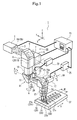
- Fig.1 is a schematic perspective view for showing an important portion of a laser beam hardening device to which the present invention is applied
- Fig.2 is a block diagram for showing an important portion of a NC unit
- Fig.3 is a schematic view for showing contents of laser beam output value memory
- Fig.4 is a view for showing a hardening track of laser beam
- Fig.5 is a schematic view for showing contents of each data block in the laser beam output value memory
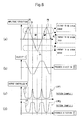
- Fig.6(a) is a chart for showing the track of laser beam (hardening cycle)
- Fig.6(b) is a chart for showing velocity of laser beam corresponding to (a) with respect to a workpiece
- Fig.6(c) is a chart for showing an example of a laser beam output pattern corresponding to (a)
- Fig.6(d) is a chart for showing the other example of the laser beam output pattern corresponding to (a).
- the upper reflection barrel 6 is provided with a first reflecting mirror 9, and the upper reflection barrel 6 is provided with a duct 10, being free to stretch and to position in a Z-axis direction which is up and down direction, and being free to rotate, drive and position in an A-axis direction with the Z-axis as its center.
- a lower reflection barrel 11 is provided, and the lower reflection barrel 11 is provided with a second reflecting mirror 12.
- An infrared thermometer 22 is connected with the beam splitter 20 through a pickup 22a, and a NC unit 23 is connected with the infrared thermometer 22.
- the NC unit 23 is connected with a head drive unit 26 for driving the hardening head 7 and the laser beam oscillator 2.
- the laser beam hardening device 1 has the above-mentioned structure.
- the workpiece 27 is located on a workpiece table (not shown) on the lower hand of the torch 24, as shown in Fig.1 so as to execute a hardening action on the basis of a hardening program produced in advance, corresponding to the workpiece 27 to be hardened through the NC unit 23 in the above-mentioned state.
- the NC unit 23 drives a table (not shown) so as to move and drive the workpiece 27 in the X-axis direction which is a horizontal direction, orthogonal to the Y-axis, and drives the head drive unit 26 so as to move and drive the hardening head 7 including the torch 24 in the Y-axis direction and Z-axis direction and so as to properly rotate and drive the lower reflection barrel 11 in the direction as shown by the arrow A together with the side reflection barrel 15, and so as to properly rotate and drive the side reflection barrel 15 in the direction as shown by the arrow B so that the torch 24 can be faced to a portion to be hardened of the workpiece 27.
- the laser beam 29 entered in the third reflecting mirror is reflected for the lower hand of the figure, that is, in the direction of the workpiece 27 by the third reflecting mirror, and is collected by the condensing lens 21 so as to aim on the workpiece 27. Then, the workpiece 27 is suddenly heated by injecting the laser beam 29 so as to harden.
- the workpiece 27 is fed in the arrow X direction by a driving mechanism (not shown) driven by the NC unit 23 at a predetermined feed velocity, and the NC unit 23 drives the mirror oscillating unit 17 through the mirror control unit 25 on the basis of a width to be hardened W1 instructed by the hardening program so as to vibrate the third reflecting mirror 16 in the direction as shown by the arrows D and E.
- the laser beam 29 entered in the third reflecting mirror 16 is vibrated with the vidth W1 in the direction (the Y-axis direction) orthogonal to the arrow X-axis direction which is the direction of feeding the workpiece 27, and the workpiece 27 is heated within the bounds of the width W1 by the vibrating laser beam 29 up to a predetermined temperature so as to be hardened.
- the direction of relatively moving the workpiece 27 with respect to the torch 24 is the X-axis direction for making the explanation simple.
- the control axis at the time of positioning the torch 24 with respect to the workpiece 27 is the A-axis which is a rotation axis around the Z-axis and the B-axis which is a rotation axis around the Y-axis in addition to the three control axes respectively orthogonal to each other, that is, the X-axis, the Y-axis and the Z-axis. Then, an optional three-dimensional positioning is possible with respect to the workpiece 27, and any direction of the three-dimensional space is available as the direction of hardening the workpiece 27.
- thermometer 22 it is necessary to correctly measure a temperature of a portion to be hardened 27a of the workpiece 27 in order to properly harden the portion to be hardened 27a.
- the temperature of the portion to be hardened 27a is measured by the infrared thermometer 22.
- the infrared radiation measured by the infrared thermometer 22 is the infrared element of a reflected light 29a from an aiming portion 27b on which the laser beam 29 aims at present, and the reflected light 29a irradiates the beam splitter 20 through the condensing lens 21 and the third reflecting mirror 16 from the aiming portion 27a of the workpiece 27, and is reflected for the upper hand of the figure by the beam splitter 20 and is injected into the pickup 22a of the infrared thermometer 22 so as to be obtained.
- the infrared thermometer 22 can measure the temperature of the portion to be hardened 27a on which hardening is actually executed by irradiating the laser beam 29 at this time by the pickup 22a with real time. That is, the beam splitter 20 for giving the reflecting light 29a to the pickup 22a is located on the optical path between the laser beam oscillator 2 and the third reflecting mirror 16 which is the beam oscillating reflection mirror for oscillating the laser beam 29 with respect to the portion to be hardened 27a of the workpiece 27, and is not located on the condensing lens 21 side downstream of the third reflecting mirror 16 oscillating the laser beam 29.
- the beam splitter 20 may be located at any position between the condensing lens 21 and the laser beam oscillator 2, but it is desirable that the beam splitter 20 is located on the condensing lens 21 side, if possible, taking the damping of the reflecting mirror 29a into consideration.
- the NC unit judges as to whether or not the temperature reaches the hardening temperature set by the hardening program and properly controls to properly adjust the output of the laser beam oscillator 2 so that the temperature of the portion to be hardened 27a can become the hardening temperature determined by the hardening program, as described hereinafter.
- control of the hardening temperature may be possible by adjusting the feeding velocity of the workpiece 27 or adjusting the vibrating cycle of the laser beam by the mirror oscillating unit 17.
- the above-mentioned embodiment refers to the beam splitter 20 which passes the laser beam from the laser beam oscillator 2 as it is and reflects the reflecting light 29a from the portion to be hardened 27a of the workpiece 27, but any reflecting method of the beam splitter 20 is available.
- a relative velocity V of the track TR of the laser beam 29 with respect to the workpiece is shown in Fig.6(b).
- the velocity V of the laser beam 29 becomes zero when the track TR reaches a peak PK of its vibration amplitude, and becomes the maximum at the position near a median MP of the amplitude.
- the laser beam 29 aims the workpiece 27, maintaining a constant output of the laser beam oscillator 2, the energy density of the laser beam irradiating the workpiece 27 per unit area is made higher near the peak PK of the amplitude where the relative velocity V is late, and the energy density of the laser beam irradiating the workpiece 27 per unit area is made lower near the median MP of the amplitude where the relative velocity V is fast. If the laser beam 29 irradiates the workpiece 27 so as to harden in the above-mentioned state, the hardening is made uneven extending for the whole length of the track TR due to the dispersion of the energy giving density.
- the NC unit 23 divides the oscillating cycle of the third reflecting mirror 16 in the direction as shown by the arrows D and E, that is, the track TR of the laser beam, by a predetermined sampling time SP, as shown in Fig.4.
- one cycle of the track TR (the time necessary for one reciprocation of the third reflecting mirror 16, the track of the laser beam on the workpiece in 10ms, for instance, this cycle is referred as "hardening cycle” hereinafter) is divided into ten parts.
- the target laser beam output computing portion 36 stores the target laser beam output ROT obtained and the measured temperature TP corresponding therewith together with the data showing the time of measuring temperature ( (1) through (10) in the figure) in the corresponding address of the data block n0 of the laser beam output value memory 37, as shown in Fig.5(a).
- the measured temperature TP of time (1) and the target laser beam output ROT at this time are stored in the address n01
- the measured temperature TP of time (2) and the target laser beam output ROT at this time are stored in the address n02
- the measured temperature TP of time (3) and the target laser beam output ROT at this time are stored in the address n03.
- the measured temperature TP of time (10) and the target laser beam output ROT at this time are stored in the address n00 in a similar way so as to store the measured temperature TP of the portion to be hardened 27a and the target laser beam output ROT for one cycle.
- the measured temperature TP is stored at the portion on which "Temperature” is displayed of n0k (k:1 through 9, 0) in each address, numeral in parentheses for right hand with respect to “Temperature” shows the sampling time, and the target laser beam output ROT is stored ,as "600W" for instance, on the further right hand.
- the temperature of each portion to be hardened 27a and the laser beam output for changing the temperature of the portion to be hardened 27a into a predetermined hardening temperature determined by the hardening program computed as the target laser beam output ROT in each time (1) through (10) concerning one of the oscillating cycles of the third reflecting mirror 16 showing "Cycle 0" of Fig.4 are stored.
- the NC unit 23 adjusts the output of the laser beam oscillator 2 so as to become the target laser beam output ROT on the basis of the temperature of each portion to be hardened 27a and the target laser beam output ROT for changing the temperature of the portion to be hardened 27a into a predetermined hardening temperature determined by the hardening program concerning "cycle 0" stored in this way so as to change the temperature of the portion to be hardened 27a into the predetermined hardening temperature determined by the hardening program and so as to execute proper hardening on the workpiece 27.
- a predetermined delay time is necessary in order to control the laser beam oscillator 2 so as to reach the target laser beam output ROT computed.
- the third reflecting mirror 16 is oscillated and driven in the direction as shown by the arrows D and E before computing the measured temperature TP and the target laser beam output ROT in some portion to be hardened 27a. Then, even if the output of the laser beam oscillator 2 is adjusted immediately the target laser beam output ROT is computed, the laser beam 29 adjusted to the target laser beam output ROT irradiates a shifted position without irradiating the portion to be hardened 27a to which the target laser beam output ROT is computed.
- the main control portion 30 gets the laser beam output synchronous control portion 39 to execute output control of the laser beam oscillator 2 on the basis of the measured temperature TP obtained and the target laser beam output ROT corresponding to the measured temperature TP in "cycle 0" of Fig.4 in the hardening cycle after m cycles (M: integral number of 1 or more), that is, in "cycle m” of Fig.4.
- M integral number of 1 or more
- the laser beam oscillator 2 is controlled so that the target laser beam output ROT obtained in each point of time (1) through (10) in "cycle 0" can occur in each point of time (1') through (10') corresponding therewith in “cycle m” .
- the laser beam output synchronous control portion 39 can control the laser beam oscillator 2, taking the delay time necessary for the control of the laser beam oscillator 2 into consideration. Therefore, the output of the laser beam oscillator 2 is adjusted to the target laser beam output ROT and is controlled at the same phase of the portion to be hardened after m cycles correctly, and the portion to be hardened 27a is correctly heated up to the temperature near the hardening temperature determined by the hardening program so as to execute proper hardening action.
- the main control portion 30 computes the measured temperature TP of the portion to be hardened 27a and the target laser beam output ROT in the points of time (1) through (10) divided into ten of 1ms in subsequent cycle 1, cycle 2 ?? cycle m-1 in a similar way above-mentioned so as to store each in the address of the corresponding data block of the laser beam output value memory 37.
- the measured temperature TP and the target laser beam output ROT in each time (1) through (10) in cycle 1 subsequent to cycle 0 are respectively stored in the address n1k (k: 1 through 9, 0) of the data block n1 as shown in Fig.5(b), and the measured temperature TP and the target laser beam output ROT in each time (1) through (10) in cycle m-1 just before cycle m are respectively stored in the address n(m-1)k (k: 1 through 9, 0) of the data block n(m-1) as shown in Fig.5(c).
- the storing form of the data block in the laser beam output value memory 37 is that m numbers of data blocks from the data block 0 to the data block n(m-1) are annularly connected and located, as typically shown in Fig.3.
- the laser beam output synchronous control portion 39 collectively reads out the next (m+1)th data block, that is, the data of the data block n0 storing the data of cycle 0 so as to store in a proper buffer memory, as shown in Fig.5(d).
- the laser beam output synchronous control portion 39 reads out the target laser beam output ROT in the corresponding time out of the buffer memory as shown in Fig.5(d) a predetermined time before the hardening cycle reaches each time of (1') through (10'), and instructs the laser beam oscillator control portion 40 to change the laser beam output at this time into the target laser beam output ROT. Receiving this instruction, the laser beam oscillator control portion 40 controls the laser beam output of the laser beam oscillator 2 so as to become the target laser beam output ROT at the time.
- 600w of the laser beam irradiates the portion to be hardened 27a of the workpiece 27 at the time (1') after a predetermined time, and the portion is heated up to a predetermined hardening temperature determined by the hardening program, approximating the predetermined hardening temperature in comparison with the temperature in the time of cycle 0 so as to execute hardening action.
- the corresponding target laser beam output ROT of the time (2), (3), ... ... (9), (10) of cycle 0 is read out so as to control to change the laser beam output ROT into the target laser beam output ROT in cycle m a predetermined time before the laser beam 29 reaches the time (2'), (3'), ... ... (9'), (10').
- the portion to be hardened is heated up to the predetermined hardening temperature determined by the program in all sampling time of cycle m, approximating the predetermined hardening temperature in comparison with the temperature in the time of cycle 0 so as to execute the hardening action.
- the temperature of the portion to be hardened 27a is measured and the target laser beam output ROT is computed in each sampling time (2'), (3'), ... ... (9'), (10') concerning cycle m as mentioned before. And, the result is newly stored in the data block n0 collectively read out at the time of executing the hardening cycle of cycle m of the laser beam output value memory 37, as shown in Fig.5(a).
- the laser beam output is controlled on the basis of' the measured temperature TP of the portion to be hardened 27a obtained in the past hardening cycle before m cycles and the target laser beam output ROT corresponding to the measured temperature TP, and furthermore, the temperature is measured in the hardening cycle in the controlled state and the corresponding target laser beam output ROT is computed so as to influence the next hardening cycle after m cycles. Therefore, the hardening temperature of the portion to be hardened 27a in each hardening cycle is controlled, unlimitedly approaching the hardening temperature designated by the hardening program every time the hardening cycle is repeated.
- the moving velocity of the laser beam 29 approaches zero in both end portions of the amplitude of the laser beam of the hardening cycle as shown in Fig.6(a) and (b), and then, the density of energy giving to the workpiece 27 per unit area becomes high.
- the laser beam output ROT of each time in each data block the laser beam output is most narrowed as shown in the time (1), (5), (6), and (10) of each data block of Fig.5 so that the workpiece 27 can be prevented from melting by giving excess energy to the portion to be hardened 27a of the workpiece 27.
- the moving velocity of the laser beam 29 becomes gradually high in the center portion of the amplitude of the laser beam of the hardening cycle and is the highest near the position where the amplitude is zero and is gradually decreased thereafter, as shown in Fig.6(b). Then, the density of the energy giving to the workpiece 27 per unit area becomes gradually low, and is gradually increased thereafter.
- the laser beam output is adjusted in such a manner that the laser beam output is increased with approaching the point where the amplitude is zero from the time (1) or (6)and is decreased for the time (5) or (10) with the amplitude zero as a peak as shown in the times (2), (3), (4), (7), (8), (9) of the respective data blocks of Fig.5, so that equal energy can be given to the portion to be hardened 27a of the workpiece 27 over all amplitude of the laser beam, that is, over the hardening cycle, and the hardening temperature of the workpiece 27 can be kept the hardening temperature determined by the hardening program in all hardening cycles.
- the target laser beam output ROT is computed on the basis of the measured temperature TP detected of the portion to be hardened 27a so as to become a predetermined hardening temperature determined by the hardening program at the target laser beam output computing portion 36, and the temperature of the portion to be hardened 27a is controlled so as to become a predetermined hardening temperature in such a manner that the laser beam output of the laser beam oscillator 2 is made the target laser beam output ROT in the corresponding portion to be hardened 27a of the hardening cycle after at least one cycle on the basis of the target laser beam output ROT computed.
- an open loop control may be also possible in the present invention in addition to the feedback loop mentioned before so long as the laser beam output of both end portions of the amplitude of the laser beam can be made lower in comparison with one of the center portion in the hardening with laser beam for hardening the workpiece 27 by oscillating the laser beam over a predetermined width W1.
- the NC unit 23 is provided with an output pattern memory 41, connecting with the bus line 31, as shown by a broken line of Fig.2.
- a laser beam output pattern LOP1, LOP2 or the like wherein laser beam output LP is made low on both sides of the amplitude of laser beam, that is, on both sides of the hardening cycle, and the laser beam output LP is made high in the center portion as shown in Fig.6(c) or Fig.6(d) is stored.
- a plurality of laser output patterns LOP1 or LOP2 are prepared according to the shape and the material of a workpiece so as to properly selectively use.
- the laser beam output pattern LOP1 or LOP2 is read out of the output pattern memory 41, and the laser beam output synchronous control portion 39 adjusts the output of the laser beam injected from the laser beam oscillator 2 on the basis of the laser beam output pattern LOP1 or LOP2 according to the position where the third reflecting mirror oscillates by the reflecting mirror position computing portion 32, that is, the position of the portion to be hardened 27a in the hardening cycle.
Landscapes
- Physics & Mathematics (AREA)
- Optics & Photonics (AREA)
- Engineering & Computer Science (AREA)
- Mechanical Engineering (AREA)
- Plasma & Fusion (AREA)
- Chemical & Material Sciences (AREA)
- Thermal Sciences (AREA)
- Crystallography & Structural Chemistry (AREA)
- Materials Engineering (AREA)
- Metallurgy (AREA)
- Organic Chemistry (AREA)
- Heat Treatment Of Articles (AREA)
- Laser Beam Processing (AREA)
Applications Claiming Priority (4)
| Application Number | Priority Date | Filing Date | Title |
|---|---|---|---|
| JP2001332993 | 2001-10-30 | ||
| JP2001332993A JP2003138314A (ja) | 2001-10-30 | 2001-10-30 | レーザ焼入れ装置 |
| JP2001379381A JP3922686B2 (ja) | 2001-12-13 | 2001-12-13 | レーザ焼入れ制御方法及びレーザ焼入れ装置 |
| JP2001379381 | 2001-12-13 |
Publications (2)
| Publication Number | Publication Date |
|---|---|
| EP1308525A2 true EP1308525A2 (fr) | 2003-05-07 |
| EP1308525A3 EP1308525A3 (fr) | 2004-01-28 |
Family
ID=26624215
Family Applications (1)
| Application Number | Title | Priority Date | Filing Date |
|---|---|---|---|
| EP02023451A Ceased EP1308525A3 (fr) | 2001-10-30 | 2002-10-21 | Procédé pour contrôler le durcissement par faisceau laser et dispositif pour durcir par faisceau laser |
Country Status (3)
| Country | Link |
|---|---|
| US (1) | US6922420B2 (fr) |
| EP (1) | EP1308525A3 (fr) |
| CN (1) | CN1417354A (fr) |
Cited By (6)
| Publication number | Priority date | Publication date | Assignee | Title |
|---|---|---|---|---|
| WO2005080686A1 (fr) * | 2004-02-23 | 2005-09-01 | Sandro Favilli | Durcissement laser d'equipements ferroviaires, et materiel a cet effet |
| WO2014037281A2 (fr) * | 2012-09-06 | 2014-03-13 | Etxe-Tar, S.A. | Procédé et système de durcissement laser d'une surface d'une pièce à usiner |
| WO2016146646A1 (fr) | 2015-03-17 | 2016-09-22 | Ikergune A.I.E. | Procédé et système de traitement thermique de tôles |
| US10648056B2 (en) | 2014-03-11 | 2020-05-12 | Etxe-Tar, S.A. | Method and system for laser hardening of a surface of a workplace |
| EP3674427A1 (fr) | 2018-12-28 | 2020-07-01 | Etxe-Tar, S.A. | Procédé et système de chauffage à l'aide d'un faisceau d'énergie |
| BE1027475B1 (fr) * | 2020-01-22 | 2021-02-26 | Laser Eng Applications | Procédé de traitement thermique en volume et système associé |
Families Citing this family (19)
| Publication number | Priority date | Publication date | Assignee | Title |
|---|---|---|---|---|
| JP2005334923A (ja) * | 2004-05-26 | 2005-12-08 | Yamazaki Mazak Corp | レーザ加工機におけるピアシング加工方法 |
| JP5459256B2 (ja) * | 2011-04-08 | 2014-04-02 | 株式会社安川電機 | ロボットシステム |
| CN103128439B (zh) * | 2011-11-24 | 2015-05-20 | 三菱电机株式会社 | 透镜单元以及激光加工装置 |
| CN103215411B (zh) * | 2013-02-06 | 2015-07-08 | 武汉新瑞达激光工程有限责任公司 | 一种激光淬火方法及装置 |
| CN103290177A (zh) * | 2013-06-15 | 2013-09-11 | 江苏和昊激光科技有限公司 | 全自动高能激光表面硬化系统 |
| US9575486B2 (en) * | 2014-03-26 | 2017-02-21 | Mitsubishi Electric Research Laboratories, Inc. | Oscillator-based path planning for machining of a pocket shape in workpiece |
| CN104498677A (zh) * | 2015-01-04 | 2015-04-08 | 宁波英飞迈材料科技有限公司 | 一种高通量微区快速热处理设备及其热处理方法 |
| WO2018042414A1 (fr) * | 2016-08-28 | 2018-03-08 | ACS Motion Control Ltd. | Procédé et système d'usinage laser de pièces relativement grandes |
| US20180094334A1 (en) * | 2016-09-30 | 2018-04-05 | Lear Corporation | Laser spot hardening |
| DE102017111541A1 (de) * | 2017-05-26 | 2018-11-29 | Walzengießerei Coswig GmbH | Oberflächengehärtetes rotationssymmetrisches Werkstück, Härtungsverfahren und Härtungsvorrichtung |
| CN108127249A (zh) * | 2017-12-20 | 2018-06-08 | 广东省焊接技术研究所(广东省中乌研究院) | 一种焦点控制激光焊接方法 |
| CN110373531B (zh) * | 2018-04-13 | 2021-07-27 | 杭州巨星科技股份有限公司 | 刃口的处理方法、具有刃口的构件及具有刃口的工具 |
| CN109234513B (zh) * | 2018-10-10 | 2019-12-13 | 华中科技大学 | 一种钢轨激光热处理的过程控制方法 |
| JP6636115B1 (ja) * | 2018-10-22 | 2020-01-29 | 株式会社アマダホールディングス | レーザ加工機及びレーザ加工方法 |
| DE102019121861A1 (de) * | 2019-08-14 | 2021-02-18 | Hueck Rheinische Gmbh | Verfahren und Vorrichtung zum Herstellen eines Presswerkzeugs |
| CN112111628A (zh) * | 2020-09-04 | 2020-12-22 | 江苏徐工工程机械研究院有限公司 | 一种激光淬火质量均匀性控制方法及装置 |
| CN112553412B (zh) * | 2020-12-25 | 2022-07-08 | 广州科技贸易职业学院 | 一种模具表面激光淬火设备及控制方法 |
| CN113549737B (zh) * | 2021-07-09 | 2022-10-04 | 华中科技大学 | 一种多光束激光淬火方法与装置 |
| CN114085957A (zh) * | 2021-10-29 | 2022-02-25 | 上海柴孚机器人有限公司 | 一种机器人跟进式激光淬火方法 |
Citations (2)
| Publication number | Priority date | Publication date | Assignee | Title |
|---|---|---|---|---|
| EP0822027A1 (fr) * | 1996-08-03 | 1998-02-04 | INPRO Innovationsgesellschaft für fortgeschrittene Produktionssysteme in der Fahrzeugindustrie mbH | Procédé de durcissement de la surface d'une pièce à travailler au moyen d'un faisceau, en particulier un faisceau laser et dispositif de réalisation de ce procédé |
| DE19853733C1 (de) * | 1998-11-23 | 2000-02-24 | Fraunhofer Ges Forschung | Verfahren zur lokal gezielten Wärmebehandlung von Werkstückoberflächen |
Family Cites Families (8)
| Publication number | Priority date | Publication date | Assignee | Title |
|---|---|---|---|---|
| US4539461A (en) | 1983-12-21 | 1985-09-03 | The Garrett Corporation | Method and apparatus for laser gear hardening |
| JPH04272122A (ja) | 1991-02-28 | 1992-09-28 | Nissan Motor Co Ltd | レーザ加工装置 |
| JPH0618433A (ja) | 1992-06-30 | 1994-01-25 | Mitsubishi Electric Corp | ボンディング装置及び方法 |
| JP2720744B2 (ja) * | 1992-12-28 | 1998-03-04 | 三菱電機株式会社 | レーザ加工機 |
| US5427733A (en) * | 1993-10-20 | 1995-06-27 | United Technologies Corporation | Method for performing temperature-controlled laser sintering |
| US5554415A (en) * | 1994-01-18 | 1996-09-10 | Qqc, Inc. | Substrate coating techniques, including fabricating materials on a surface of a substrate |
| JP3162254B2 (ja) * | 1995-01-17 | 2001-04-25 | 三菱電機株式会社 | レーザ加工装置 |
| US6217695B1 (en) * | 1996-05-06 | 2001-04-17 | Wmw Systems, Llc | Method and apparatus for radiation heating substrates and applying extruded material |
-
2002
- 2002-10-21 EP EP02023451A patent/EP1308525A3/fr not_active Ceased
- 2002-10-22 CN CN02146576A patent/CN1417354A/zh active Pending
- 2002-10-25 US US10/280,385 patent/US6922420B2/en not_active Expired - Fee Related
Patent Citations (2)
| Publication number | Priority date | Publication date | Assignee | Title |
|---|---|---|---|---|
| EP0822027A1 (fr) * | 1996-08-03 | 1998-02-04 | INPRO Innovationsgesellschaft für fortgeschrittene Produktionssysteme in der Fahrzeugindustrie mbH | Procédé de durcissement de la surface d'une pièce à travailler au moyen d'un faisceau, en particulier un faisceau laser et dispositif de réalisation de ce procédé |
| DE19853733C1 (de) * | 1998-11-23 | 2000-02-24 | Fraunhofer Ges Forschung | Verfahren zur lokal gezielten Wärmebehandlung von Werkstückoberflächen |
Cited By (21)
| Publication number | Priority date | Publication date | Assignee | Title |
|---|---|---|---|---|
| WO2005080686A1 (fr) * | 2004-02-23 | 2005-09-01 | Sandro Favilli | Durcissement laser d'equipements ferroviaires, et materiel a cet effet |
| GB2520214B (en) * | 2012-09-06 | 2017-05-03 | Etxe-Tar S A | Method and system for laser hardening of a surface of a workpiece |
| WO2014037281A3 (fr) * | 2012-09-06 | 2014-06-26 | Etxe-Tar, S.A. | Procédé et système de durcissement laser d'une surface d'une pièce à usiner |
| GB2520214A (en) * | 2012-09-06 | 2015-05-13 | Etxetar Sa | Method and system for laser hardening of a surface of a workpiece |
| KR20150054901A (ko) * | 2012-09-06 | 2015-05-20 | 에체-따르 에세.아. | 공작물 표면 레이저 경화 방법 및 시스템 |
| KR102299377B1 (ko) | 2012-09-06 | 2021-09-08 | 에체-따르 에세.아. | 공작물 표면 레이저 경화 방법 및 시스템 |
| KR20210013308A (ko) * | 2012-09-06 | 2021-02-03 | 에체-따르 에세.아. | 공작물 표면 레이저 경화 방법 및 시스템 |
| DE112013004368B4 (de) * | 2012-09-06 | 2017-08-03 | Etxe-Tar, S.A. | Verfahren und System zum Laserhärten einer Oberfläche eines Werkstücks |
| DE112013004368B8 (de) * | 2012-09-06 | 2018-01-25 | Etxe-Tar, S.A. | Verfahren und System zum Laserhärten einer Oberfläche eines Werkstücks |
| US10138528B2 (en) | 2012-09-06 | 2018-11-27 | Etxe-Tar, S.A. | Method and system for laser hardening of a surface of a workpiece |
| WO2014037281A2 (fr) * | 2012-09-06 | 2014-03-13 | Etxe-Tar, S.A. | Procédé et système de durcissement laser d'une surface d'une pièce à usiner |
| US10961597B2 (en) | 2012-09-06 | 2021-03-30 | Exteotar, S.A. | Method and system for laser hardening of a surface of a workpiece |
| KR102211009B1 (ko) | 2012-09-06 | 2021-02-03 | 에체-따르 에세.아. | 공작물 표면 레이저 경화 방법 및 시스템 |
| US10648056B2 (en) | 2014-03-11 | 2020-05-12 | Etxe-Tar, S.A. | Method and system for laser hardening of a surface of a workplace |
| US10864603B2 (en) | 2015-03-17 | 2020-12-15 | Ikergune A.I.E. | Method and system for heat treatment of sheet metal |
| WO2016146646A1 (fr) | 2015-03-17 | 2016-09-22 | Ikergune A.I.E. | Procédé et système de traitement thermique de tôles |
| WO2020136110A1 (fr) | 2018-12-28 | 2020-07-02 | Etxe-Tar, S.A. | Procédé et système de chauffage au moyen d'un faisceau d'énergie |
| EP3674427A1 (fr) | 2018-12-28 | 2020-07-01 | Etxe-Tar, S.A. | Procédé et système de chauffage à l'aide d'un faisceau d'énergie |
| EP4234149A2 (fr) | 2018-12-28 | 2023-08-30 | Etxe-Tar, S.A. | Procédé et système de chauffage à l'aide d'un faisceau d'énergie |
| BE1027475B1 (fr) * | 2020-01-22 | 2021-02-26 | Laser Eng Applications | Procédé de traitement thermique en volume et système associé |
| WO2021148600A1 (fr) * | 2020-01-22 | 2021-07-29 | Laser Engineering Applications | Procede de traitement thermique en volume et systeme associe |
Also Published As
| Publication number | Publication date |
|---|---|
| US6922420B2 (en) | 2005-07-26 |
| US20030080098A1 (en) | 2003-05-01 |
| EP1308525A3 (fr) | 2004-01-28 |
| CN1417354A (zh) | 2003-05-14 |
Similar Documents
| Publication | Publication Date | Title |
|---|---|---|
| EP1308525A2 (fr) | Procédé pour contrôler le durcissement par faisceau laser et dispositif pour durcir par faisceau laser | |
| CN105658372B (zh) | 通过激光束加工工件的方法、激光刀具、激光加工机、及机器控制 | |
| JP6626036B2 (ja) | 測定機能を有するレーザ加工システム | |
| CN107717211B (zh) | 机器人系统和激光加工方法 | |
| CA2489941A1 (fr) | Methode et poste de soudage laser | |
| JP5459256B2 (ja) | ロボットシステム | |
| CN110181170A (zh) | 激光加工装置 | |
| CN101189097B (zh) | 激光加工装置及激光加工方法 | |
| CN101269442B (zh) | 激光焊接装置及其方法 | |
| JP6325646B1 (ja) | ロボットを用いてレーザ加工を行うレーザ加工ロボットシステム及びレーザ加工ロボットの制御方法 | |
| KR20080039359A (ko) | 레이저 용접 장치 및 그 방법, 및 조사 장치 | |
| CN109719386A (zh) | 激光加工系统 | |
| EP2406033A1 (fr) | Appareil de soudure au laser | |
| KR20060131849A (ko) | 가상 레이저 마킹 시스템 및 방법 | |
| US5302802A (en) | Laser robot and method of controlling same, and light beam deflector and control signal generator therefor | |
| JP2009523629A (ja) | レーザー溶接方法 | |
| JPH10264067A (ja) | 作業線探索機能を備えたロボット−レーザセンサシステム | |
| JPS6062487A (ja) | 産業用ロボツト装置 | |
| JPH05154681A (ja) | レーザ加工機における光路長固定装置 | |
| JP2018528079A (ja) | 加工ヘッドを加工対象のトラックに沿ってガイドする方法 | |
| JP2007021551A (ja) | レーザ溶接装置およびレーザ溶接システム | |
| JP3922686B2 (ja) | レーザ焼入れ制御方法及びレーザ焼入れ装置 | |
| JP2000329885A5 (fr) | ||
| JP2003138314A (ja) | レーザ焼入れ装置 | |
| JP4497985B2 (ja) | ガルバノスキャナの制御方法及びガルバノスキャナの制御装置並びにレーザ加工機 |
Legal Events
| Date | Code | Title | Description |
|---|---|---|---|
| PUAI | Public reference made under article 153(3) epc to a published international application that has entered the european phase |
Free format text: ORIGINAL CODE: 0009012 |
|
| AK | Designated contracting states |
Designated state(s): AT BE BG CH CY CZ DE DK EE ES FI FR GB GR IE IT LI LU MC NL PT SE SK TR |
|
| AX | Request for extension of the european patent |
Extension state: AL LT LV MK RO SI |
|
| RIC1 | Information provided on ipc code assigned before grant |
Ipc: 7B 23K 26/00 - Ipc: 7B 23K 26/42 B Ipc: 7B 23K 26/06 B Ipc: 7B 23K 26/08 B Ipc: 7C 21D 11/00 B Ipc: 7C 21D 1/09 A |
|
| PUAL | Search report despatched |
Free format text: ORIGINAL CODE: 0009013 |
|
| AK | Designated contracting states |
Kind code of ref document: A3 Designated state(s): AT BE BG CH CY CZ DE DK EE ES FI FR GB GR IE IT LI LU MC NL PT SE SK TR |
|
| AX | Request for extension of the european patent |
Extension state: AL LT LV MK RO SI |
|
| 17P | Request for examination filed |
Effective date: 20040728 |
|
| AKX | Designation fees paid |
Designated state(s): DE FR GB IT |
|
| 17Q | First examination report despatched |
Effective date: 20040922 |
|
| STAA | Information on the status of an ep patent application or granted ep patent |
Free format text: STATUS: THE APPLICATION HAS BEEN REFUSED |
|
| 18R | Application refused |
Effective date: 20060225 |