EP1307035A2 - Téléphone mobile - Google Patents
Téléphone mobile Download PDFInfo
- Publication number
- EP1307035A2 EP1307035A2 EP02023816A EP02023816A EP1307035A2 EP 1307035 A2 EP1307035 A2 EP 1307035A2 EP 02023816 A EP02023816 A EP 02023816A EP 02023816 A EP02023816 A EP 02023816A EP 1307035 A2 EP1307035 A2 EP 1307035A2
- Authority
- EP
- European Patent Office
- Prior art keywords
- case
- sub
- mobile phone
- display unit
- led
- Prior art date
- Legal status (The legal status is an assumption and is not a legal conclusion. Google has not performed a legal analysis and makes no representation as to the accuracy of the status listed.)
- Granted
Links
Images


Classifications
-
- H—ELECTRICITY
- H04—ELECTRIC COMMUNICATION TECHNIQUE
- H04M—TELEPHONIC COMMUNICATION
- H04M1/00—Substation equipment, e.g. for use by subscribers
- H04M1/02—Constructional features of telephone sets
- H04M1/0202—Portable telephone sets, e.g. cordless phones, mobile phones or bar type handsets
- H04M1/0206—Portable telephones comprising a plurality of mechanically joined movable body parts, e.g. hinged housings
- H04M1/0208—Portable telephones comprising a plurality of mechanically joined movable body parts, e.g. hinged housings characterized by the relative motions of the body parts
- H04M1/0214—Foldable telephones, i.e. with body parts pivoting to an open position around an axis parallel to the plane they define in closed position
-
- H—ELECTRICITY
- H04—ELECTRIC COMMUNICATION TECHNIQUE
- H04M—TELEPHONIC COMMUNICATION
- H04M1/00—Substation equipment, e.g. for use by subscribers
- H04M1/72—Mobile telephones; Cordless telephones, i.e. devices for establishing wireless links to base stations without route selection
- H04M1/724—User interfaces specially adapted for cordless or mobile telephones
-
- H—ELECTRICITY
- H04—ELECTRIC COMMUNICATION TECHNIQUE
- H04M—TELEPHONIC COMMUNICATION
- H04M1/00—Substation equipment, e.g. for use by subscribers
- H04M1/02—Constructional features of telephone sets
- H04M1/0202—Portable telephone sets, e.g. cordless phones, mobile phones or bar type handsets
- H04M1/0206—Portable telephones comprising a plurality of mechanically joined movable body parts, e.g. hinged housings
- H04M1/0241—Portable telephones comprising a plurality of mechanically joined movable body parts, e.g. hinged housings using relative motion of the body parts to change the operational status of the telephone set, e.g. switching on/off, answering incoming call
- H04M1/0245—Portable telephones comprising a plurality of mechanically joined movable body parts, e.g. hinged housings using relative motion of the body parts to change the operational status of the telephone set, e.g. switching on/off, answering incoming call using open/close detection
-
- H—ELECTRICITY
- H04—ELECTRIC COMMUNICATION TECHNIQUE
- H04M—TELEPHONIC COMMUNICATION
- H04M1/00—Substation equipment, e.g. for use by subscribers
- H04M1/02—Constructional features of telephone sets
- H04M1/23—Construction or mounting of dials or of equivalent devices; Means for facilitating the use thereof
- H04M1/236—Construction or mounting of dials or of equivalent devices; Means for facilitating the use thereof including keys on side or rear faces
-
- H—ELECTRICITY
- H04—ELECTRIC COMMUNICATION TECHNIQUE
- H04M—TELEPHONIC COMMUNICATION
- H04M2250/00—Details of telephonic subscriber devices
- H04M2250/16—Details of telephonic subscriber devices including more than one display unit
Definitions
- the present invention relates to a mobile phone of a folding type.
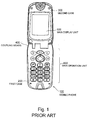
- Fig. 1 is a plan view showing a structure of a conventional mobile phone of a folding type.
- a first case 200 and a second case 300 are coupled by use of coupling means 400.
- the conventional mobile phone has a structure in which the second case 300 can be opened and closed.
- Such a mobile phone 100 of a folding type has a feature in that the mobile phone 100 is easy to be housed because of compactness thereof in a state where the mobile phone 100 is folded.
- Fig. 1 shows a plan view of the mobile phone 100 when the.second case 300 is opened.
- the first case 200 is provided with a main operation unit 600 for entering a phone number and performing various operations on a main surface thereof.
- the main operation unit 600 is provided with a plurality of operation keys including a menu key, a cursor key, a select key, a cancel key, and a short cut key, for example.
- the second case 300 is provided with a main display unit 500 of a liquid crystal display (LCD) on a main surface thereof, the main surface facing the main operation unit 600 in the state where the mobile phone 100 is folded.
- the main display unit 500 displays character information such as a phone number and an electronic mail.
- Aback surface (not shown) of the second case 300 is provided with a light emitting diode (LED) for indicating an incoming call, the LED lighting up upon receiving an incoming call.
- LED light emitting diode
- the first case 200 is provided with a control unit (not shown) and a storage unit (not shown).
- the control unit is intended to select and set various functions included in the mobile phone 100 in accordance with instructions entered by use of the operation keys.
- the storage unit stores image information to be displayed on the main display unit 500 and various types of information registered by a user.
- a description will be given by taking as an example a case in which a ring tone (Ringer Call) of the mobile phone 100 is set to a desired sound or melody. It is assumed that plural kinds of ring tones or melodies are previously registered in the storage unit.
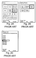
- Figs. 2A to 2C are plan views showing examples of screens which are to be displayed on the main display unit of the mobile phone 100 shown in Fig. 1.
- the control unit causes the main display unit 500 to display a menu screen shown in Fig. 2A.
- the control unit determines a setting of "Setting Phone” and causes the main display unit 500 to display a select screen shown in Fig. 2B. At this time, it is also possible to cancel the determination of the "Setting Phone” by pushing the cancel key.
- the control unit determines a setting of "Ringer Call” and causes the main display unit 500 to display a select screen shown in Fig. 2C.
- the control unit determines a setting of "Melody 1."
- the user in order for a user to set a desired function for the mobile phone 100, the user is required to operate the operation keys for a number of times. Accordingly, the user has to take a lot of time and efforts to operate.
- the conventional mobile phone 100 is very inconvenient particularly in a case where the user wants to change a setting frequently.
- a short cut key is intended to be used for solving such a problem. By registering a specific select item previously, it is possible to jump to a desired select screen in one operation with the short cut key.
- the main display unit and the main operation unit cover each other, and therefore there is a problem in which the main display unit cannot be watched and in which an operation by use of the main operation unit cannot be performed. Moreover, if the main operation unit cannot be operated, it is also impossible to use a short cut function as described above. Accordingly, in a case where the user frequently changes the ring tone or the color of light of the LED for indicating an incoming call, the user has to open the second case 300 every time the user makes a change. Thus, the user takes a lot of time and efforts.
- the present invention is intended to solve the above described problems inherent in the conventional technology. It is an object of the present invention to provide a mobile phone in which a ring tone and a color of light of an LED for indicating an incoming call are easily changed even in a state where the mobile phone is folded.
- a mobile phone of the present invention is a mobile phone of a folding type which includes a first case and a second case, the first case including a main operation unit, the second case including a main display unit on a main surface thereof, the main operation unit and the main display unit being covered in a state where the mobile phone is folded.
- the mobile phone includes: a sub-display unit which can be watched in the state where the mobile phone is folded, the sub-display unit being provided on any one of the first case and the second case; a sub-operation unit which can be operated in the state where the mobile phone is folded, the sub-operation unit being provided on any one of the first case and the second case; and a control unit for setting a useful function for a case in which a change is made in accordance with an operation by use of the sub-operation unit in a state where the first case and the second case are folded.
- the sub-display unit may be located on a back surface of the second case, the back surface being reverse to the main surface of the second case.
- the sub-operation unit may be located on a side surface of the first case, the side surface being along a long edge of the first case.
- the sub-operation unit may include a short cut function for setting a useful function for a case in which a change is performed in a state where the mobile phone is folded.
- the sub-operation unit may include a select key for selecting a ring tone which is previously registered and a scroll key for changing a types of the ring tone, and the sub-display unit may display the type of the ring tone in accordance with an operation of the scroll key.
- the sub-operation unit may include a select key for selecting a color of light of an LED for indicating an incoming call, the LED being previously provided on the second case; and a scroll key for changing the color of light of the LED for indicating an incoming call, and the sub-display unit may display a color type of light of the LED for indicating an incoming call in accordance with an operation of the scroll key.
- a mobile phone of a structure as described above has a sub-display unit and a sub-operation unit, each of which is, provided on any one of a first case and a second case.
- a sub-display unit and a sub-operation unit each of which is, provided on any one of a first case and a second case.
- the sub-operation unit is located on a side surface of the first case along a long edge of the first case, it is possible to secure a larger area for providing operation keys in comparison with a case where the sub-operation unit is located on a side surface of the first case along a short edge of the first case.
- FIG. 3 is a view showing a structure of a mobile phone according to the present invention, and is a plan view showing a state in which the mobile phone is folded.
- Fig. 4 is a side view showing the mobile phone shown in Fig. 3 in a state where a second case thereof is opened, which is viewed from a long edge thereof.
- Fig. 5 is a block diagram showing a structure of internal circuits of the mobile phone according to the present invention.
- the mobile phone of the present invention has a structure in which the second case 3 is provided with a sub-display unit 8 and an LED 9 for indicating an incoming call, both of which can be watched even in a state where the mobile phone is folded.
- the second case 3 is attached to a first case 2 by use of coupling means 4.
- a main display unit 5 is provided on a surface (main surface) of the second case 3, the surface being positioned at the front when the second case 3 is opened.
- the sub-display unit 8 is provided on a back surface of the second case 3, the back surface being reverse to the main surface on which the main display unit 5 is provided.
- a main operation unit 6 (illustration thereof is omitted in Fig. 4) is provided at the front of the first case 2.
- the main operation unit 6 has a button and key switches such as a dial key, a scroll key, and a cursor key.
- a sub-operation unit 10 is provided on a side surface of the first case 2.
- the sub-operation unit 10 is provided with a first operation key 11, a second operation key 12, and a third operation key 13.
- a short cut function for setting a useful function (for example, a ring tone, an LED for indicating an incoming call, or the like) for a case in which a change is made in a state where the mobile phone is folded; and a short cut function in which a function cannot be set unless the first to third operation keys 11 to 13 are operated in a state where the mobile phone is unfolded.
- a useful function denotes a function which can be changed only by checking display on the sub-display unit 8 and operating with the sub-operation unit 10.
- a short cut function denotes a function of making it possible to jump to a desired select screen in one operation of a key by previously registering a specific select item in the storage unit 15.
- the first to third operation keys 11 to 13 are set as keys for executing a short cut function.
- a predetermined short cut function can be registered in the storage unit 15 while being made to directly correspond to any one of the first to third operation keys 11 to 13 by an operation of the main operation unit 6. Moreover, it may be adopted that, when a function is registered while being made to correspond to a short cut key, the same function is simultaneously set to any one of the first to third operation keys 11 to 13.
- the first operation key 11 is used as a short cut key or a select key.
- the second operation key 12 and the third operation key 13 are used as scroll keys for scrolling character information displayed on the sub-display unit 8 in a forward direction and a backward direction.
- Fig. 4 shows a structure in which the sub-operation unit 10 is provided on the side surface of the first case 2 along the long edge of the first case 2.
- the sub-operation unit 10 may be provided on a side surface of the second case 3 along a long edge of the second case 3, or on a side surface of the first case 2 or the second case 3 along a short edge of the first case 2 or the second case 3.
- the sub-operation unit 10 may be formed on any surface as far as the sub-operation unit 10 is located at a position where the sub-operation unit 10 can be watched from an outside when the second case 3 is closed or where the sub-operation unit 10 can be operated in a state in which the second case 3 is closed.
- the mobile phone of the present invention is structured so as to include a control unit 14 and the storage unit 15.
- the control unit 14 is intended to select and set various functions included in the mobile phone in accordance with instructions entered by use of the operation keys of the main operation unit 6 or the sub-operation unit 10.
- the storage unit 15 stores image information to be displayed on the main display unit 5 and the sub-display unit 8 and various pieces of information registered by a user.
- the control unit 14 has a structure including a CPU and a recording medium on which a control program is recorded for causing the CPU to execute select and setting processes of the various functions of the mobile phone, for example.
- the CPU executes processes described below in accordance with the control program recorded on the recording medium.
- a folding/unfolding detection unit 16 detects whether the second case 3 is in an open state or in a closed state.
- Fig. 6 is a flowchart showing the operation procedures of the mobile phone shown in Fig. 3.
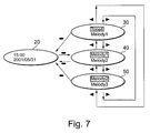
- Fig. 7 is a view showing a screen of the sub-display unit 8 shown in Fig. 3, and is a plan view showing an example of a setting screen for the ring tone.
- Step S1 if the user of the mobile phone pushes the first operation key 11, the control unit 14 firstly determines whether or not a short cut function is registered as a function to be executed in accordance with an operation of the sub-operation unit 10 in the storage unit 15 (Step S1).
- control unit 14 causes the sub-display unit 8 to display the current date and time similarly to the standby state as shown in a display screen 20 in Fig. 7.
- the control unit 14 determines whether or not the short cut function registered in the storage unit 15 is a useful function for a case in which the user changes a setting for the ring tone, the LED for indicating an incoming call, or the like in a state where the mobile phone is folded (Step S2).
- the control unit 14 causes the sub-display unit 8 to display the current date and time similarly to the standby state.
- the control unit 14 causes the sub-display unit 8 to display a select screen corresponding to the registered short cut function (Step S3).
- a setting function for the ring tone is registered.
- the control unit 14 causes the sub-display unit 8 to display a select screen for selecting "Melody 1" or "Melody 2" as shown in a display screen 40 in Fig. 7, for example.
- the user can scroll the screen by pushing the second operation key 12 or the third operation key 13 of the sub-operation unit 10 to display a select screen for selecting "Tone 4" or "Melody 3" as shown in a display screen 30 or 50 in Fig. 7, for example.
- the control unit 14 determines a setting of the ring tone which is designated by the cursor.
- control unit 14 causes the sub-display unit 8 to display the current date and time again similarly to the standby state.
- the user can easily change a setting by operating the sub-operation unit 10 while watching the sub-display unit 8 even in a state where the mobile phone is folded. Moreover, it is not necessary to open the second case 3 every time the user makes a setting, thus saving trouble in comparison with a conventional mobile phone.
- a plurality of short cut functions can be registered correspondingly to the sub-operation unit 10 as functions which can be selected.
- the number of operation keys should be increased in response to the number of functions which can be selected.
- the sub-operation unit 10 is located on the side surface of the first case 2 or the second case 3 along the long edge of the first case 2 or the second case 3
- a mobile phone of the present invention has a sub-display unit and a sub-operation unit, each of which is provided on any one of a first case and a second case.
- a sub-display unit and a sub-operation unit each of which is provided on any one of a first case and a second case.
- the present invention facilitates a change of a setting.
- the sub-operation unit is located on a side surface of the first case along a long edge of the first case.
- the sub-operation unit is located on a side surface of the first case along a long edge of the first case.
- a plurality of short cut functions can be registered correspondingly to the sub-operation unit as functions which can be selected.
Landscapes
- Engineering & Computer Science (AREA)
- Signal Processing (AREA)
- Human Computer Interaction (AREA)
- Computer Networks & Wireless Communication (AREA)
- Telephone Set Structure (AREA)
- Telephone Function (AREA)
Applications Claiming Priority (2)
| Application Number | Priority Date | Filing Date | Title |
|---|---|---|---|
| JP2001329095 | 2001-10-26 | ||
| JP2001329095A JP2003134204A (ja) | 2001-10-26 | 2001-10-26 | 携帯電話機 |
Publications (3)
| Publication Number | Publication Date |
|---|---|
| EP1307035A2 true EP1307035A2 (fr) | 2003-05-02 |
| EP1307035A3 EP1307035A3 (fr) | 2004-03-17 |
| EP1307035B1 EP1307035B1 (fr) | 2005-10-12 |
Family
ID=19145051
Family Applications (1)
| Application Number | Title | Priority Date | Filing Date |
|---|---|---|---|
| EP02023816A Expired - Lifetime EP1307035B1 (fr) | 2001-10-26 | 2002-10-23 | Téléphone mobile |
Country Status (6)
| Country | Link |
|---|---|
| US (1) | US7181250B2 (fr) |
| EP (1) | EP1307035B1 (fr) |
| JP (1) | JP2003134204A (fr) |
| CN (1) | CN1243440C (fr) |
| DE (1) | DE60206585T2 (fr) |
| HK (1) | HK1056464A1 (fr) |
Cited By (3)
| Publication number | Priority date | Publication date | Assignee | Title |
|---|---|---|---|---|
| WO2005120020A1 (fr) * | 2004-06-03 | 2005-12-15 | Frog Design Hartmut Esslinger Gmbh | Terminal mobile a mecanisme pivotant tournant |
| EP1914965A1 (fr) * | 2006-10-20 | 2008-04-23 | LG Electronics, Inc. | Terminal ayant une fonction de modification de couleur et procédé de modification de couleur de celui-ci |
| WO2009009154A1 (fr) * | 2007-07-11 | 2009-01-15 | Sony Ericsson Mobile Communications Ab | Système d'affichage pour des dispositifs électroniques portables avec des écrans secondaires liés |
Families Citing this family (22)
| Publication number | Priority date | Publication date | Assignee | Title |
|---|---|---|---|---|
| US6807433B2 (en) * | 2002-03-18 | 2004-10-19 | Kabushiki Kaisha Toshiba | Mobile communication terminal with unanswered incoming-call notifying function |
| USD487736S1 (en) | 2003-06-17 | 2004-03-23 | Matsushita Electric Industrial Co., Ltd. | Mobile phone |
| USD488791S1 (en) | 2003-06-17 | 2004-04-20 | Matsushita Electric Industrial Co., Ltd. | Mobile phone |
| USD487071S1 (en) | 2003-06-17 | 2004-02-24 | Matsushita Electric Industrial Co., Ltd. | Mobile phone |
| US8090396B2 (en) * | 2003-06-30 | 2012-01-03 | Motorola Mobility, Inc. | Push-to-talk features in wireless communications devices and methods |
| USD491907S1 (en) | 2003-10-16 | 2004-06-22 | Sanyo Electric Co., Ltd. | Mobile phone |
| FI116641B (fi) * | 2003-10-24 | 2006-01-13 | Nokia Corp | Menetelmä elektronisessa laitteessa olevan pikavalinnan muuttamiseksi, laitteen näyttöyksikkö sekä elektroninen laite |
| CA2531524A1 (fr) * | 2003-10-31 | 2005-05-12 | Iota Wireless Llc | Entree de donnees concurrentes |
| US20080129552A1 (en) * | 2003-10-31 | 2008-06-05 | Iota Wireless Llc | Concurrent data entry for a portable device |
| US20050170865A1 (en) * | 2004-01-30 | 2005-08-04 | Nokia Corporation | Tune cutting feature |
| WO2005088943A1 (fr) * | 2004-03-12 | 2005-09-22 | Matsushita Electric Industrial Co., Ltd. | Dispositif de terminal portable |
| JP3856453B2 (ja) * | 2004-03-23 | 2006-12-13 | シャープ株式会社 | 折り畳み式携帯通信端末 |
| CN1993968B (zh) | 2004-05-31 | 2013-01-02 | 夏普株式会社 | 便携式通信终端 |
| JP2006113166A (ja) * | 2004-10-13 | 2006-04-27 | Nec Saitama Ltd | イルミネーション構造、および電子機器 |
| US20060150106A1 (en) * | 2004-12-30 | 2006-07-06 | Paivi Jokinen | Mobile communication terminal |
| JP2007150891A (ja) * | 2005-11-29 | 2007-06-14 | Kyocera Corp | 電子機器及び電子機器制御方法 |
| US7673256B2 (en) * | 2006-03-31 | 2010-03-02 | Research In Motion Limited | Method and apparatus for indicating mobile electronic device status or state |
| JP4863969B2 (ja) * | 2007-11-12 | 2012-01-25 | 富士通東芝モバイルコミュニケーションズ株式会社 | 情報処理装置 |
| JP4565002B2 (ja) | 2007-12-28 | 2010-10-20 | 京セラ株式会社 | 携帯通信端末 |
| KR101107016B1 (ko) | 2010-09-02 | 2012-01-25 | (주)블루버드 소프트 | 모바일 단말기 |
| KR101107014B1 (ko) | 2010-09-02 | 2012-01-25 | (주)블루버드 소프트 | 모바일 단말기 및 그 제조방법 |
| DE202021000619U1 (de) | 2021-03-05 | 2021-06-25 | Katelyn Belinszki | Autonome sekundäre Anzeigevorrichtung für Mobiltelefone |
Citations (5)
| Publication number | Priority date | Publication date | Assignee | Title |
|---|---|---|---|---|
| JP2000036974A (ja) * | 1999-06-11 | 2000-02-02 | Matsushita Electric Ind Co Ltd | 通信端末装置 |
| US6125286A (en) * | 1997-06-05 | 2000-09-26 | Motorola, Inc. | Communication device having multiple displays and method of operating the same |
| WO2000059179A1 (fr) * | 1999-03-31 | 2000-10-05 | Sony Electronics Inc. | Dispositif electronique a affichage reversible |
| GB2355145A (en) * | 1999-10-08 | 2001-04-11 | Nokia Mobile Phones Ltd | Portable device with a multifunction and multimode user input key providing a shortcut back to a particular state of the device |
| GB2358318A (en) * | 1999-11-05 | 2001-07-18 | Matsushita Electric Ind Co Ltd | Folding portable telephone and video game apparatus |
Family Cites Families (15)
| Publication number | Priority date | Publication date | Assignee | Title |
|---|---|---|---|---|
| CA2100397C (fr) * | 1992-08-04 | 1998-07-14 | Matthew D. Mottier | Interrupteur a double fonction |
| JPH07273843A (ja) * | 1994-03-25 | 1995-10-20 | Nec Corp | 携帯無線機の着信通報方法及び通報装置 |
| JPH1168896A (ja) * | 1997-08-11 | 1999-03-09 | Nec Corp | 携帯無線機 |
| FI106904B (fi) * | 1998-12-08 | 2001-04-30 | Nokia Mobile Phones Ltd | Langaton viestin ja ohjauselin |
| JP3767219B2 (ja) | 1998-12-22 | 2006-04-19 | 株式会社デンソー | 通信装置 |
| FR2791854B1 (fr) | 1999-04-01 | 2001-05-11 | Sfr Sa | Terminal telephonique pourvu de moyens de gestion de la visualisation de menus et procede correspondant |
| JP2000358086A (ja) | 1999-06-16 | 2000-12-26 | Health Support Japan:Kk | 携帯電話 |
| JP2001086204A (ja) | 1999-09-10 | 2001-03-30 | Matsushita Electric Ind Co Ltd | 携帯電話機 |
| JP3296803B2 (ja) | 1999-10-07 | 2002-07-02 | 三洋電機株式会社 | 電話装置 |
| JP4201442B2 (ja) | 1999-11-05 | 2008-12-24 | パナソニック株式会社 | 折畳式携帯電話装置 |
| JP2001211240A (ja) | 2000-01-27 | 2001-08-03 | Kyocera Corp | 携帯無線機 |
| JP2001268165A (ja) | 2000-03-17 | 2001-09-28 | Kenwood Corp | 電話機 |
| KR100528715B1 (ko) * | 2000-10-18 | 2005-11-15 | 산요덴키가부시키가이샤 | 폴더식 통신단말장치 및 자동발신방법 |
| JP2002305570A (ja) * | 2001-04-04 | 2002-10-18 | Nec Corp | 移動電話機 |
| JP2002320012A (ja) | 2001-04-20 | 2002-10-31 | Nec Access Technica Ltd | 液晶ディスプレイ付き電子機器 |
-
2001
- 2001-10-26 JP JP2001329095A patent/JP2003134204A/ja active Pending
-
2002
- 2002-10-23 EP EP02023816A patent/EP1307035B1/fr not_active Expired - Lifetime
- 2002-10-23 DE DE60206585T patent/DE60206585T2/de not_active Expired - Lifetime
- 2002-10-25 US US10/279,973 patent/US7181250B2/en not_active Expired - Lifetime
- 2002-10-26 CN CNB021558302A patent/CN1243440C/zh not_active Expired - Fee Related
-
2003
- 2003-11-28 HK HK03108711A patent/HK1056464A1/xx not_active IP Right Cessation
Patent Citations (5)
| Publication number | Priority date | Publication date | Assignee | Title |
|---|---|---|---|---|
| US6125286A (en) * | 1997-06-05 | 2000-09-26 | Motorola, Inc. | Communication device having multiple displays and method of operating the same |
| WO2000059179A1 (fr) * | 1999-03-31 | 2000-10-05 | Sony Electronics Inc. | Dispositif electronique a affichage reversible |
| JP2000036974A (ja) * | 1999-06-11 | 2000-02-02 | Matsushita Electric Ind Co Ltd | 通信端末装置 |
| GB2355145A (en) * | 1999-10-08 | 2001-04-11 | Nokia Mobile Phones Ltd | Portable device with a multifunction and multimode user input key providing a shortcut back to a particular state of the device |
| GB2358318A (en) * | 1999-11-05 | 2001-07-18 | Matsushita Electric Ind Co Ltd | Folding portable telephone and video game apparatus |
Non-Patent Citations (1)
| Title |
|---|
| PATENT ABSTRACTS OF JAPAN vol. 2000, no. 05, 14 September 2000 (2000-09-14) & JP 2000 036974 A (MATSUSHITA ELECTRIC IND CO LTD), 2 February 2000 (2000-02-02) * |
Cited By (3)
| Publication number | Priority date | Publication date | Assignee | Title |
|---|---|---|---|---|
| WO2005120020A1 (fr) * | 2004-06-03 | 2005-12-15 | Frog Design Hartmut Esslinger Gmbh | Terminal mobile a mecanisme pivotant tournant |
| EP1914965A1 (fr) * | 2006-10-20 | 2008-04-23 | LG Electronics, Inc. | Terminal ayant une fonction de modification de couleur et procédé de modification de couleur de celui-ci |
| WO2009009154A1 (fr) * | 2007-07-11 | 2009-01-15 | Sony Ericsson Mobile Communications Ab | Système d'affichage pour des dispositifs électroniques portables avec des écrans secondaires liés |
Also Published As
| Publication number | Publication date |
|---|---|
| CN1422055A (zh) | 2003-06-04 |
| EP1307035B1 (fr) | 2005-10-12 |
| EP1307035A3 (fr) | 2004-03-17 |
| JP2003134204A (ja) | 2003-05-09 |
| US7181250B2 (en) | 2007-02-20 |
| US20030083107A1 (en) | 2003-05-01 |
| DE60206585T2 (de) | 2006-07-13 |
| DE60206585D1 (de) | 2006-02-23 |
| CN1243440C (zh) | 2006-02-22 |
| HK1056464A1 (en) | 2004-02-13 |
Similar Documents
| Publication | Publication Date | Title |
|---|---|---|
| US7181250B2 (en) | Mobile phone | |
| EP0860972B1 (fr) | Téléphone affichant les différentes fonctionnalités d'une touche multifonction | |
| JP3955969B2 (ja) | 移動体電話機 | |
| US7233813B2 (en) | Portable terminal apparatus and display control program thereof | |
| RU2305910C2 (ru) | Способ и устройство отображения для мобильного терминала | |
| EP1832095B1 (fr) | Terminal mobile, et procedes associes, a interface utilisateur amelioree | |
| US7925305B2 (en) | Portable communication terminal | |
| EP0898405A2 (fr) | Dispositif terminal de communication d'information | |
| US8036724B2 (en) | Portable data terminal and function selecting and starting method used therein | |
| JP2003298699A (ja) | スライド型携帯電話機 | |
| US20050143137A1 (en) | Terminal apparatus | |
| WO2002031807A1 (fr) | Dispositif de saisie de donnees | |
| US20030153283A1 (en) | Mobile phone | |
| KR100486516B1 (ko) | 휴대폰의 대기화면 설정방법 | |
| JP2004179870A (ja) | 携帯端末装置 | |
| JP4161561B2 (ja) | 移動体端末、そのポインタ制御方法、およびそのプログラム | |
| JP2002156958A (ja) | 表示装置および電子装置 | |
| JP2006211266A (ja) | 携帯電話機 | |
| JP2002101181A (ja) | 情報処理装置 | |
| JPH0429426A (ja) | 小型携帯無線電話装置 | |
| US20060150106A1 (en) | Mobile communication terminal | |
| JP2005151483A (ja) | 通信端末装置 | |
| JP2000151790A (ja) | ワンタッチダイヤルキーを備えた通信端末装置 | |
| JP2004128675A (ja) | 重ね型携帯端末装置 | |
| JP2009246554A (ja) | 携帯電話機 |
Legal Events
| Date | Code | Title | Description |
|---|---|---|---|
| PUAI | Public reference made under article 153(3) epc to a published international application that has entered the european phase |
Free format text: ORIGINAL CODE: 0009012 |
|
| AK | Designated contracting states |
Designated state(s): AT BE BG CH CY CZ DE DK EE ES FI FR GB GR IE IT LI LU MC NL PT SE SK TR |
|
| AX | Request for extension of the european patent |
Extension state: AL LT LV MK RO SI |
|
| PUAL | Search report despatched |
Free format text: ORIGINAL CODE: 0009013 |
|
| AK | Designated contracting states |
Kind code of ref document: A3 Designated state(s): AT BE BG CH CY CZ DE DK EE ES FI FR GB GR IE IT LI LU MC NL PT SE SK TR |
|
| AX | Request for extension of the european patent |
Extension state: AL LT LV MK RO SI |
|
| RIC1 | Information provided on ipc code assigned before grant |
Ipc: 7H 04M 1/247 A Ipc: 7H 04M 1/725 B Ipc: 7H 04M 1/02 B |
|
| 17P | Request for examination filed |
Effective date: 20040211 |
|
| 17Q | First examination report despatched |
Effective date: 20040517 |
|
| AKX | Designation fees paid |
Designated state(s): DE FR GB IT |
|
| GRAP | Despatch of communication of intention to grant a patent |
Free format text: ORIGINAL CODE: EPIDOSNIGR1 |
|
| GRAS | Grant fee paid |
Free format text: ORIGINAL CODE: EPIDOSNIGR3 |
|
| GRAA | (expected) grant |
Free format text: ORIGINAL CODE: 0009210 |
|
| AK | Designated contracting states |
Kind code of ref document: B1 Designated state(s): DE FR GB IT |
|
| REG | Reference to a national code |
Ref country code: GB Ref legal event code: FG4D |
|
| REF | Corresponds to: |
Ref document number: 60206585 Country of ref document: DE Date of ref document: 20060223 Kind code of ref document: P |
|
| ET | Fr: translation filed | ||
| PLBE | No opposition filed within time limit |
Free format text: ORIGINAL CODE: 0009261 |
|
| STAA | Information on the status of an ep patent application or granted ep patent |
Free format text: STATUS: NO OPPOSITION FILED WITHIN TIME LIMIT |
|
| 26N | No opposition filed |
Effective date: 20060713 |
|
| REG | Reference to a national code |
Ref country code: GB Ref legal event code: 732E Free format text: REGISTERED BETWEEN 20141023 AND 20141029 |
|
| REG | Reference to a national code |
Ref country code: FR Ref legal event code: TP Owner name: LENOVO INNOVATIONS LIMITED (HONG KONG), HK Effective date: 20141119 |
|
| PGFP | Annual fee paid to national office [announced via postgrant information from national office to epo] |
Ref country code: FR Payment date: 20141008 Year of fee payment: 13 |
|
| PGFP | Annual fee paid to national office [announced via postgrant information from national office to epo] |
Ref country code: IT Payment date: 20141016 Year of fee payment: 13 |
|
| PG25 | Lapsed in a contracting state [announced via postgrant information from national office to epo] |
Ref country code: IT Free format text: LAPSE BECAUSE OF NON-PAYMENT OF DUE FEES Effective date: 20151023 |
|
| REG | Reference to a national code |
Ref country code: FR Ref legal event code: ST Effective date: 20160630 |
|
| PG25 | Lapsed in a contracting state [announced via postgrant information from national office to epo] |
Ref country code: FR Free format text: LAPSE BECAUSE OF NON-PAYMENT OF DUE FEES Effective date: 20151102 |
|
| REG | Reference to a national code |
Ref country code: DE Ref legal event code: R082 Ref document number: 60206585 Country of ref document: DE Representative=s name: GLAWE DELFS MOLL PARTNERSCHAFT MBB VON PATENT-, DE Ref country code: DE Ref legal event code: R081 Ref document number: 60206585 Country of ref document: DE Owner name: LENOVO INNOVATIONS LIMITED, HK Free format text: FORMER OWNER: NEC CORP., TOKYO, JP |
|
| PGFP | Annual fee paid to national office [announced via postgrant information from national office to epo] |
Ref country code: GB Payment date: 20181031 Year of fee payment: 17 |
|
| PGFP | Annual fee paid to national office [announced via postgrant information from national office to epo] |
Ref country code: DE Payment date: 20181228 Year of fee payment: 17 |
|
| REG | Reference to a national code |
Ref country code: DE Ref legal event code: R119 Ref document number: 60206585 Country of ref document: DE |
|
| PG25 | Lapsed in a contracting state [announced via postgrant information from national office to epo] |
Ref country code: DE Free format text: LAPSE BECAUSE OF NON-PAYMENT OF DUE FEES Effective date: 20200501 |
|
| GBPC | Gb: european patent ceased through non-payment of renewal fee |
Effective date: 20191023 |
|
| PG25 | Lapsed in a contracting state [announced via postgrant information from national office to epo] |
Ref country code: GB Free format text: LAPSE BECAUSE OF NON-PAYMENT OF DUE FEES Effective date: 20191023 |