EP1306711A1 - Objectif a focale variable et camera video equipee de cet objectif - Google Patents
Objectif a focale variable et camera video equipee de cet objectif Download PDFInfo
- Publication number
- EP1306711A1 EP1306711A1 EP01934394A EP01934394A EP1306711A1 EP 1306711 A1 EP1306711 A1 EP 1306711A1 EP 01934394 A EP01934394 A EP 01934394A EP 01934394 A EP01934394 A EP 01934394A EP 1306711 A1 EP1306711 A1 EP 1306711A1
- Authority
- EP
- European Patent Office
- Prior art keywords
- lens
- lens group
- positive
- focal length
- negative
- Prior art date
- Legal status (The legal status is an assumption and is not a legal conclusion. Google has not performed a legal analysis and makes no representation as to the accuracy of the status listed.)
- Withdrawn
Links
Images


Classifications
-
- G—PHYSICS
- G02—OPTICS
- G02B—OPTICAL ELEMENTS, SYSTEMS OR APPARATUS
- G02B15/00—Optical objectives with means for varying the magnification
- G02B15/14—Optical objectives with means for varying the magnification by axial movement of one or more lenses or groups of lenses relative to the image plane for continuously varying the equivalent focal length of the objective
- G02B15/16—Optical objectives with means for varying the magnification by axial movement of one or more lenses or groups of lenses relative to the image plane for continuously varying the equivalent focal length of the objective with interdependent non-linearly related movements between one lens or lens group, and another lens or lens group
- G02B15/163—Optical objectives with means for varying the magnification by axial movement of one or more lenses or groups of lenses relative to the image plane for continuously varying the equivalent focal length of the objective with interdependent non-linearly related movements between one lens or lens group, and another lens or lens group having a first movable lens or lens group and a second movable lens or lens group, both in front of a fixed lens or lens group
- G02B15/167—Optical objectives with means for varying the magnification by axial movement of one or more lenses or groups of lenses relative to the image plane for continuously varying the equivalent focal length of the objective with interdependent non-linearly related movements between one lens or lens group, and another lens or lens group having a first movable lens or lens group and a second movable lens or lens group, both in front of a fixed lens or lens group having an additional fixed front lens or group of lenses
- G02B15/173—Optical objectives with means for varying the magnification by axial movement of one or more lenses or groups of lenses relative to the image plane for continuously varying the equivalent focal length of the objective with interdependent non-linearly related movements between one lens or lens group, and another lens or lens group having a first movable lens or lens group and a second movable lens or lens group, both in front of a fixed lens or lens group having an additional fixed front lens or group of lenses arranged +-+
-
- G—PHYSICS
- G02—OPTICS
- G02B—OPTICAL ELEMENTS, SYSTEMS OR APPARATUS
- G02B13/00—Optical objectives specially designed for the purposes specified below
- G02B13/18—Optical objectives specially designed for the purposes specified below with lenses having one or more non-spherical faces, e.g. for reducing geometrical aberration
-
- G—PHYSICS
- G02—OPTICS
- G02B—OPTICAL ELEMENTS, SYSTEMS OR APPARATUS
- G02B15/00—Optical objectives with means for varying the magnification
- G02B15/14—Optical objectives with means for varying the magnification by axial movement of one or more lenses or groups of lenses relative to the image plane for continuously varying the equivalent focal length of the objective
- G02B15/144—Optical objectives with means for varying the magnification by axial movement of one or more lenses or groups of lenses relative to the image plane for continuously varying the equivalent focal length of the objective having four groups only
- G02B15/1441—Optical objectives with means for varying the magnification by axial movement of one or more lenses or groups of lenses relative to the image plane for continuously varying the equivalent focal length of the objective having four groups only the first group being positive
- G02B15/144113—Optical objectives with means for varying the magnification by axial movement of one or more lenses or groups of lenses relative to the image plane for continuously varying the equivalent focal length of the objective having four groups only the first group being positive arranged +-++
Definitions
- the present invention relates to a zoom lens and a video camera using the same. More specifically, the present invention relates to a high-magnification aspherical zoom lens that achieves a high magnification (zoom ratio: 23 times), high brightness (an F number of 1.6), low cost and a long back-focus, as well as to a video camera using the same.
- a zoom lens that incorporates a plastic lens is disclosed in, for example, JP 8(1996)-106046 A, JP 9(1997)-311272 A.
- JP 8(1996)-106046 A discloses a zoom lens including ten lenses, four of which are plastic lenses, to provide a zoom ratio of 12 times.
- JP 9(1997)-311272 A discloses a zoom lens including ten lenses, five of which are plastic lenses, to provide a zoom ratio of 18 times.
- a zoom lens includes: a first lens group having positive refracting power and being fixed with respect to the image plane; a second lens group having negative refracting power and varying power by moving along an optical axis; a third lens group having positive refracting power and being fixed with respect to the image plane; and a fourth lens group having positive refracting power and moving along the optical axis so that the image plane varied by a movement of the second lens group and a movement of an object is kept at a predetermined position from a reference plane.
- the first, second, third, and fourth lens groups are arranged in this order from an object side to an image plane side.
- the first lens group includes a negative lens, a positive lens, and a positive meniscus lens arranged from the object side in this order, in which the positive meniscus lens has a convex surface on the object side.
- the second lens group includes a negative lens, a double-concave lens, and a positive lens arranged from the object side in this order, and includes at least one aspherical surface, in which the double-concave lens and the positive lens are cemented with each other.
- the third lens group includes a positive lens and a negative plastic lens arranged from the object side in this order, and includes at least one aspherical surface.
- the fourth lens group includes a negative plastic lens and a positive plastic lens that are arranged from the object side in this order and cemented with each other, and includes at least one aspherical surface.
- the following expression (36) is satisfied: 5 ⁇
- the zoom lens of the first aspect it is possible to provide a zoom lens with a high magnification at a zoom ratio of 20 times or more, while balancing various aberrations thereof well. Besides, it is possible to cancel changes in respective refractive indices of plastic lens materials caused by temperature changes, thereby reducing deviations of the position of the image plane.
- the following expression (37) preferably is satisfied: 7 ⁇
- the following expressions (38) to (41) preferably are satisfied: 9 ⁇ f1/fw ⁇ 11 1 ⁇
- the zoom lens it is possible to make the zoom lens compact, while adjusting the various aberration performances excellently.
- the following expression (42) preferably is satisfied: d12 ⁇ fw ⁇ 1.2 where d12 represents a distance between the positive lens and the negative plastic lens of the third lens group.
- a chromatic aberration can be corrected excellently in a zooming range from the wide position to a tele position.
- the following expression (43) preferably is satisfied: (sag(r1)+sag(r2)+d8)/d8 ⁇ 4.5
- sag (r1) represents a sag amount between a center of an incident surface of the double-concave lens of the second lens group and a position where the incident surface of the double-concave lens is brought into contact with an outgoing surface of the negative lens disposed on the object side in the second lens group
- sag (r2) represents a sag amount between a center and an outer-most peripheral portion of the outgoing surface of the double-concave lens
- d8 denotes a thickness of the double-concave lens.
- the double-concave lens can be formed readily, whereby the yield thereof can be improved.
- a radius of curvature of a lens surface closest to the image plane of the first lens group and a radius of curvature of a lens surface closest to the object of the second lens group are equal to each other.
- the following expression (44) preferably is satisfied: 0.6 ⁇ BF/fw ⁇ 1.1 where BF represents an air distance between an image-plane-side surface of the lens closest to the image plane and the image plane.
- this preferable example it is possible to ensure a back-focus necessary for allowing an infrared cut-off filter or a low-pass filter such as a crystal filter to be inserted. Besides, the back-focus is prevented from increasing unnecessarily, which makes it possible to provide a compact zoom lens.
- a zoom lens according to a second aspect of the present invention includes: a first lens group having positive refracting power and being fixed with respect to the image plane; a second lens group having negative refracting power and varying power by moving along an optical axis; a third lens group having positive refracting power and being fixed with respect to the image plane; and a fourth lens group having positive refracting power and moving along the optical axis so that the image plane varied by a movement of the second lens group and a movement of an object is kept at a predetermined position from a reference plane.
- the first, second, third, and fourth lens groups are arranged in this order from an object side to an image plane side.
- the first lens group includes a negative lens, a positive lens, and a positive meniscus lens arranged from the object side in this order, in which the positive meniscus lens has a convex surface on the object side.
- the second lens group includes a negative lens, a double-concave lens, and a positive lens arranged from the object side in this order, and includes at least one aspherical surface, in which the double-concave lens and the positive lens are cemented with each other.
- the third lens group includes a positive lens and a negative plastic lens arranged from the object side in this order, and includes at least one aspherical surface.
- the fourth lens group includes a positive plastic lens and a negative plastic lens that are arranged from the object side in this order and cemented with each other, and includes at least one aspherical surface.
- the following expression (45) is satisfied: 5 ⁇
- the zoom lens of the second aspect it is possible to provide a zoom lens with a high magnification at a zoom ratio of 20 times or more, while balancing various aberrations thereof well. Besides, it is possible to cancel changes in respective refractive indices of plastic lens materials caused by temperature changes, thereby reducing deviations of the position of the image plane.
- the following expression (46) preferably is satisfied: 7 ⁇
- the following expressions (47) to (50) preferably are satisfied: 9 ⁇ f1/fw ⁇ 11 1 ⁇
- the zoom lens it is possible to make the zoom lens compact, while adjusting the aberrations excellently.
- the following expression (51) preferably is satisfied: d12 ⁇ fw ⁇ 1.2 where d12 represents a distance between the positive lens and the negative plastic lens of the third lens group.
- a chromatic aberration can be corrected excellently in a zooming range from the wide position to a tele position.
- the following expression (52) preferably is satisfied: (sag(r1)+sag(r2)+d8)/d8 ⁇ 4.5
- sag (r1) represents a sag amount between a center of an incident surface of the double-concave lens of the second lens group and a position where the incident surface of the double-concave lens is brought into contact with an outgoing surface of the negative lens disposed on the object side in the second lens group
- sag (r2) represents a sag amount between a center and an outer-most peripheral portion of the outgoing surface of the double-concave lens
- d8 denotes a thickness of the double-concave lens.
- the double-concave lens can be formed readily, whereby the yield thereof can be improved.
- a radius of curvature of a lens surface closest to the image plane of the first lens group and a radius of curvature of a lens surface closest to the object of the second lens group are equal to each other.
- the following expression (53) preferably is satisfied: 0.6 ⁇ BF/fw ⁇ 1.1 where BF represents an air distance between an image-plane-side surface of the lens closest to the image plane and the image plane.
- this preferable example it is possible to ensure a back-focus necessary for allowing an infrared cut-off filter or a low-pass filter such as a crystal filter to be inserted. Besides, the back-focus is prevented from increasing unnecessarily, which makes it possible to provide a compact zoom lens.
- a zoom lens according to a third aspect of the present invention includes: a first lens group having positive refracting power and being fixed with respect to the image plane; a second lens group having negative refracting power and varying power by moving along an optical axis; a third lens group having positive refracting power and being fixed with respect to the image plane; and a fourth lens group having positive refracting power and moving along the optical axis so that the image plane varied by a movement of the second lens group and a movement of an object is kept at a predetermined position from a reference plane.
- the first, second, third, and fourth lens groups are arranged in this order from an object side to an image plane side.
- the first lens group includes a negative lens, a positive lens, and a positive meniscus lens arranged from the object side in this order, in which the positive meniscus lens has a convex surface on the object side.
- the second lens group includes a negative lens, a double-concave lens, and a positive lens arranged from the object side in this order, and includes at least one aspherical surface, in which the double-concave lens and the positive lens are cemented with each other.
- the third lens group includes a positive lens and a negative plastic lens arranged from the object side in this order, and includes at least one aspherical surface.
- the fourth lens group includes a negative plastic lens and a positive plastic lens that are arranged from the object side in this order, and includes at least one aspherical surface.
- the following expression (54) is satisfied: 5 ⁇
- the zoom lens of the third aspect it is possible to provide a zoom lens with a high magnification at a zoom ratio of 20 times or more, while balancing various aberrations thereof well. Besides, it is possible to cancel changes in respective refractive indices of plastic lens materials caused by temperature changes, thereby reducing deviations of the position of the image plane.
- the following expression (55) preferably is satisfied: 7 ⁇
- the following expressions (56) to (59) preferably are satisfied: 9 ⁇ f1/fw ⁇ 11 1 ⁇
- the zoom lens it is possible to make the zoom lens compact, while adjusting the aberrations excellently.
- the following expression (60) preferably is satisfied: d12 ⁇ fw ⁇ 1.2 where d12 represents a distance between the positive lens and the negative plastic lens of the third lens group.
- a chromatic aberration can be corrected excellently in a zooming range from the wide position to a tele position.
- the following expression (61) preferably is satisfied: (sag(r1)+sag(r2)+d8)/d8 ⁇ 4.5
- sag (r1) represents a sag amount between a center of an incident surface of the double-concave lens of the second lens group and a position where the incident surface of the double-concave lens is brought into contact with an outgoing surface of the negative lens disposed on the object side in the second lens group
- sag (r2) represents a sag amount between a center and an outer-most peripheral portion of the outgoing surface of the double-concave lens
- d8 denotes a thickness of the double-concave lens.
- the double-concave lens can be formed readily, whereby the yield thereof can be improved.
- a radius of curvature of a lens surface closest to the image plane of the first lens group and a radius of curvature of a lens surface closest to the object of the second lens group are equal to each other.
- the following expression (62) preferably is satisfied: 0.6 ⁇ BF/fw ⁇ 1.1 where BF represents an air distance between an image-plane-side surface of the lens closest to the image plane and the image plane.
- this preferable example it is possible to ensure a back-focus necessary for allowing an infrared cut-off filter or a low-pass filter such as a crystal filter to be inserted. Besides, the back-focus is prevented from increasing unnecessarily, which makes it possible to provide a compact zoom lens.
- a zoom lens according to a fourth aspect of the present invention includes: a first lens group having positive refracting power and being fixed with respect to the image plane; a second lens group having negative refracting power and varying power by moving along an optical axis; a third lens group having positive refracting power and being fixed with respect to the image plane; and a fourth lens group having positive refracting power and moving along the optical axis so that the image plane varied by a movement of the second lens group and a movement of an object is kept at a predetermined position from a reference plane.
- the first, second, third, and fourth lens groups are arranged in this order from an object side to an image plane side.
- the first lens group includes a negative lens, a positive lens, and a positive meniscus lens arranged from the object side in this order, in which the positive meniscus lens has a convex surface on the object side.
- the second lens group includes a negative lens, a double-concave lens, and a positive lens arranged from the object side in this order, and includes at least one aspherical surface, in which the double-concave lens and the positive lens are cemented with each other.
- the third lens group includes a positive lens and a negative plastic lens that are arranged from the object side in this order and cemented with each other, and includes at least one aspherical surface.
- the fourth lens group includes a negative plastic lens and a positive plastic lens that are arranged from the object side in this order and cemented with each other, and includes at least one aspherical surface.
- the following expression (63) is satisfied: 5 ⁇
- the zoom lens of the fourth aspect it is possible to provide a zoom lens with a high magnification at a zoom ratio of 20 times or more, while balancing various aberrations thereof well. Besides, it is possible to cancel changes in respective refractive indices of plastic lens materials caused by temperature changes, thereby reducing deviations of the position of the image plane.
- the following expression (64) preferably is satisfied: 7 ⁇
- the following expressions (65) to (68) preferably are satisfied: 9 ⁇ f1/fw ⁇ 11 1 ⁇
- the following expression (69) preferably is satisfied: (sag(r1)+sag(r2)+d8)/d8 ⁇ 4.5
- sag (r1) represents a sag amount between a center of an incident surface of the double-concave lens of the second lens group and a position where the incident surface of the double-concave lens is brought into contact with an outgoing surface of the negative lens disposed on the object side in the second lens group
- sag (r2) represents a sag amount between a center and an outer-most peripheral portion of the outgoing surface of the double-concave lens
- d8 denotes a thickness of the double-concave lens.
- the double-concave lens can be formed readily, whereby the yield thereof can be improved.
- a radius of curvature of a lens surface closest to the image plane of the first lens group and a radius of curvature of a lens surface closest to the object of the second lens group are equal to each other.
- the following expression (70) preferably is satisfied: 0.6 ⁇ BF/fw ⁇ 1.1 where BF represents an air distance between an image-plane-side surface of the lens closest to the image plane and the image plane.
- this preferable example it is possible to ensure a back-focus necessary for allowing an infrared cut-off filter or a low-pass filter such as a crystal filter to be inserted. Besides, the back-focus is prevented from increasing unnecessarily, which makes it possible to provide a compact zoom lens.
- a video camera according to the present invention is configured so as to include the zoom lens according to the present invention. With this configuration for the video camera, it is possible to provide a video camera that is small in size, light in weight, and produced at low cost.
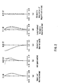
- FIG. 1 is a view showing the arrangement of a zoom lens according to Embodiment 1 of the present invention.
- the zoom lens has a structure in which a first lens group 11, a second lens group 12, a third lens group 13, a fourth lens group 14, and a glass plate 15 are arranged from an object side (left side in FIG. 1) to an image plane 16 side (right side in FIG. 1) in this order.
- the glass plate 15 is equivalent optically to a crystal filter, a face plate of an imaging device, etc.
- the first lens group 11 has positive refracting power, and is fixed with respect to the image plane 16 even when varying power and focusing.
- the second lens group 12 has negative refracting power and varies power by moving along an optical axis.
- the third lens group 13 has positive refracting power, and is fixed with respect to the image plane 16 when varying power and focusing.
- the fourth lens group 14 has positive refracting power, and moves along the optical axis so that the image plane 16 varied by the movement of the second lens group 12 and the movement of the object to be imaged is kept at a predetermined position from a reference plane, thereby moving an image and adjusting the focus thereof at the same time in accordance with variable power.
- the first lens group 11 is composed of a negative lens 1a, a positive lens 1b, and a positive meniscus lens 1c arranged from the object side in this order, in which the positive meniscus lens 1c has a convex surface on the object side.
- the second lens group 12 is composed of a negative lens 2a, and a cemented lens of a double-concave lens 2b and a positive lens 2c, which are arranged from the object side in this order, in which at least one of the surfaces of the foregoing lenses is aspherical.
- the third lens group 13 is composed of a positive lens 3a and a negative plastic lens 3b arranged from the object side in this order, in which at least one of the surfaces of these lenses is aspherical.
- the fourth lens group 14 is a cemented lens composed of a negative plastic lens 4a and a positive plastic lens 4b that are arranged from the object side in this order, in which at least one of the surfaces of these lenses is aspherical.
- the following expression (71) is satisfied: 5 ⁇
- fp1 represents a focal length of the negative plastic lens 3b of the third lens group 13
- fp2 represents a focal length of the negative plastic lens 4a of the fourth lens group 14
- fp3 represents a focal length of the positive plastic lens 4b of the fourth lens group 14
- fw represents a combined focal length of the entire system at a wide position.
- the following expressions (73) to (76) desirably are satisfied: 9 ⁇ f1/fw ⁇ 11 1 ⁇
- f1 represents a combined focal length of the first lens group 11
- f2 represents a combined focal length of the second lens group 12
- f3 represents a combined focal length of the third lens group 13
- f4 represents a combined focal length of the fourth lens group 14.
- the zoom lens is configured to be compact, with aberration performances excellently adjusted.
- the first lens group 11 has an excessive refracting power, which makes it difficult to correct a spherical aberration at the side of the long focal length and an off-axis coma-aberration.
- the length of the entire lens increases, which makes it difficult to make the zoom lens compact.
- f3/fw is not more than the lower limit of the expression (75)
- the refracting power of the third lens group 13 increases, which makes it impossible to secure a back-focus that allows a crystal filter or the like to be inserted therein, and makes it difficult to correct the spherical aberration.
- f3/fw is not less than the upper limit of the expression (75)
- a Petzval sum increases, thereby making it difficult to correct a field curvature.
- f4/fw is not more than the lower limit of the expression (76)
- the size of the entire lens system increases, which makes it difficult to make the zoom lens compact.
- f4/fw is not less than the upper limit of the expression (76)
- the following expression (77) desirably is satisfied: d12 ⁇ fw ⁇ 1.2 where d12 represents a distance between the positive lens 3a and the negative plastic lens 3b of the third lens group 13.
- a chromatic aberration can be corrected excellently in a zooming range from the wide position to the tele position. If d12 ⁇ fw is not less than the upper limit of the expression (77), the chromatic aberration varies more significantly from the wide position to the tele position, thereby significantly deteriorating the performance.
- the following expression (78) desirably is satisfied: (sag(r1)+sag(r2)+d8)/d8 ⁇ 4.5
- sag (r1) represents a sag amount between the center of an incident surface of the double-concave lens 2b of the second lens group 12 and a position where the incident surface of the double-concave lens 2b is brought into contact with an outgoing surface of the negative lens 2a disposed on the object side in the second lens group 12
- sag (r2) represents a sag amount between the center and an outer-most peripheral portion of the outgoing surface of the double-concave lens 2b
- d8 denotes a thickness of the double-concave lens 2b.
- the double-concave lens 2b can be formed readily, whereby the yield thereof can be improved. If (sag(r1)+sag(r2)+d8)/d8 is not less than the upper limit of the expression (78), the ratio of a thickness of the central portion of the lens to an edge thickness of the peripheral portion of the lens increases, making it difficult to mold a lens. As a result, the yield is lowered and a low cost of lenses cannot be realized.
- the zoom lens according to the present embodiment is configured so that a lens surface closest to the image plane of the first lens group 11 has a radius of curvature equal to a radius of curvature of a lens surface closest to the object of the second lens group 12. This prevents the distance between the surface closest to the image plane of the first lens group 11 and the surface closest to the object of the second lens group 12 from decreasing with increasing proximity to a lens periphery. This facilitates the production of a lens barrel.
- the following expression (79) desirably is satisfied: 0.6 ⁇ BF/fw ⁇ 1.1 where BF represents an air distance between an image-plane-side surface of the lens closest to the image plane and the image plane.
- Table 1 shows a specific example of the zoom lens according to the present embodiment.
- Group Surface rd th nd ⁇ 1 1 37.31 0.80 1.80518 25.4 2 20.08 5.05 1.58913 61.2 3 -277.05 0.15 4 18.82 2.75 1.60311 60.7 5 51.75 variable 2 6 51.75 0.60 1.80500 39.6 7 4.37 2.71 8* -8.59 0.80 1.60602 57.8 9 5.51 2.20 1.80518 25.5 10 71.99 variable 3 11* 8.42 3.70 1.60602 57.8 12* -10.17 0.20 13 -15.57 0.60 1.58387 30.1 14 15.57 variable 4 15* 9.60 0.60 1.58387 30.1 16 4.64 2.70 1.49178 57.2 17* -18.52 variable 5 18 ⁇ 2.80 1.51633 64.1 19 ⁇ -
- rd represents a radius of curvature (mm) of a lens
- th represents a thickness (mm) of a lens or an air distance (mm) between lenses
- nd represents a refractive index of each lens with respect to a d-line
- ⁇ represents an abbe number of each lens with respect to the d-line.
- the shape of an aspherical surface (in Table 1, such a surface is denoted with a mark * attached beside its reference number) is defined by the following equation (80).
- Z cy 2 1 + 1 - (1 + k ) c 2 y 2 + Dy 4 + Ey 6 + Fy 8 + Gy 10
- y represents a height from the optical axis
- Z represents a distance between a point on the aspherical surface at the height y from the optical axis and a tangent plane of the apex on the aspherical surface
- c represents a curvature at the apex on the aspherical surface
- k represents a conical constant
- D, E, F, and G represent aspherical coefficients.
- Table 2 shows aspherical coefficients of the zoom lens in the present example.
- Table 3 shows an air distance (mm) that is varied by zooming in the case where an object is positioned at infinity.
- Wide position Normal position Tele position
- Focal length 3.010 27.036 69.075 F
- Angle of view (2 ⁇ ) 65.136 7.614 2.954 th5 0.700 16.949 20.341 th10 21.740 5.491 2.099 th12 8.120 2.490 8.120 th17 2.000 7.630 2.000
- the normal position in Table 3 is where the third lens group 13 is placed most closely to the fourth lens group 14
- Focal length (mm), F No., and ⁇ (°) represent a focal length, an F number, and an incident angle of view at a wide position, a normal position, and a tele position of the zoom lens of the present example.
- FIGS. 2A to 2E, 3A to 3E, and 4A to 4E show performances regarding various aberrations at the wide position, the normal position, and the tele position of the zoom lens shown in the present example, respectively.
- FIGS. 2A, 3A and 4A show a spherical aberration (mm);
- FIGS. 2B, 3B and 4B show astigmatism (mm);
- FIGS. 2C, 3C and 4C show a distortion aberration (%);
- FIGS. 2D, 3D and 4D show a longitudinal chromatic aberration (mm);
- FIGS. 2E, 3E and 4E show a chromatic aberration of magnification (mm).
- FIGS. 2A, 3A and 4A show a spherical aberration (mm);
- FIGS. 2B, 3B and 4B show astigmatism (mm);
- FIGS. 2C, 3C and 4C show a distortion aberration (%);
- a solid line represents a sagittal field curvature
- a broken line represents a meridional field curvature.
- FIGS. 2D, 3D and 4D showing the longitudinal chromatic aberration and FIGS. 2E, 3E and 4E showing the chromatic aberration of magnification a solid line represents the values with respect to the d-line
- a short broken line represents the values with respect to an F-line
- a long broken line represents the values with respect to a C-line.
- the amount of movement of the image plane position according to a change in a refractive index of a plastic lens material caused by a temperature change is 0.9 ⁇ m/C° when the object is positioned at infinity and the zooming position is at the wide position.
- FIG. 5 is a view showing the arrangement of a zoom lens according to Embodiment 2 of the present invention.
- the zoom lens has a structure in which a first lens group 21, a second lens group 22, a third lens group 23, a fourth lens group 24, and a glass plate 25 are arranged from an object side (left side in FIG. 5) to an image plane 26 side (right side in FIG. 5) in this order.
- the glass plate 25 is equivalent optically to a crystal filter, a face plate of an imaging device, etc.
- the first lens group 21 has positive refracting power, and is fixed with respect to the image plane 26 even when varying power and focusing.
- the second lens group 22 has negative refracting power and varies power by moving along an optical axis.
- the third lens group 23 has positive refracting power, and is fixed with respect to the image plane 26 even when varying power and focusing.
- the fourth lens group 24 has positive refracting power, and moves along the optical axis so that the image plane 26 varied by the movement of the second lens group 22 and the movement of the object to be imaged is kept at a predetermined position from a reference plane, thereby moving an image and adjusting the focus thereof at the same time in accordance with variable power.
- the first lens group 21 is composed of a negative lens 5a, a positive lens 5b, and a positive meniscus lens 5c arranged from the object side in this order, in which the positive meniscus lens 5c has a convex surface on the object side.
- the second lens group 22 is composed of a negative lens 6a, and a cemented lens of a double-concave lens 6b and a positive lens 6c, which are arranged from the object side in this order, in which at least one of the surfaces of the foregoing lenses is aspherical.
- the third lens group 23 is composed of a positive lens 7a and a negative plastic lens 7b arranged from the object side in this order, in which at least one of the surfaces of these lenses is aspherical.
- the fourth lens group 24 is a cemented lens composed of a positive plastic lens 8a and a negative plastic lens 8b that are arranged from the object side in this order, in which at least one of the surfaces of these lenses is aspherical.
- the following expression (81) is satisfied: 5 ⁇
- fp1 represents a focal length of the negative plastic lens 7b of the third lens group 23
- fp2 represents a focal length of the positive plastic lens 8a of the fourth lens group 24
- fp3 represents a focal length of the negative plastic lens 8b of the fourth lens group 24
- fw represents a combined focal length of the entire system at a wide position.
- the following expressions (83) to (86) desirably are satisfied: 9 ⁇ f1/fw ⁇ 11 1 ⁇
- f1 represents a combined focal length of the first lens group
- f2 represents a combined focal length of the second lens group
- f3 represents a combined focal length of the third lens group 23
- f4 represents a combined focal length of the fourth lens group 24.
- the zoom lens is configured to be compact, with aberration performances excellently adjusted.
- the first lens group 21 has an excessive refracting power, which makes it difficult to correct a spherical aberration at the side of the long focal length and an off-axis coma-aberration.
- the full length of the lens increases, which makes it difficult to make the zoom lens compact.
- f3/fw is not more than the lower limit of the expression (85)
- the refracting power of the third lens group 23 increases, which makes it impossible to secure a back-focus that allows a crystal filter or the like to be inserted therein, and makes it difficult to correct the spherical aberration.
- f3/fw is not less than the upper limit of the expression (85)
- a Petzval sum increases, thereby making it difficult to correct a field curvature.
- f4/fw is not more than the lower limit of the expression (86)
- the size of the entire lens system increases, which makes it difficult to make the zoom lens compact.
- f4/fw is not less than the upper limit of the expression (86)
- the following expression (87) desirably is satisfied: d12 ⁇ fW ⁇ 1.2 where d12 represents a distance between the positive lens 7a and the negative plastic lens 7b of the third lens group 23.
- a chromatic aberration can be corrected excellently in a zooming range from the wide position to the tele position. If d12 ⁇ fw is not less than the upper limit of the expression (87), the chromatic aberration significantly varies from the wide position to the tele position, thereby significantly deteriorating the performance.
- the following expression (88) desirably is satisfied: (sag(r1)+sag(r2)+d8)/d8 ⁇ 4.5
- sag (r1) represents a sag amount between the center of an incident surface of the double-concave lens 6b of the second lens group 22 and a position where the incident surface of the double-concave lens 6b is brought into contact with an outgoing surface of the negative lens 6a disposed on the object side in the second lens group 22
- sag (r2) represents a sag amount between the center and an outer-most peripheral portion of the outgoing surface of the double-concave lens 6b
- d8 denotes a thickness of the double-concave lens 6b.
- the double-concave lens 6b can be formed readily, whereby the yield thereof can be improved. If (sag(r1)+sag(r2)+d8)/d8 is not less than the upper limit of the expression (88), the ratio of a thickness of the central portion of the lens to an edge thickness of the peripheral portion of the lens increases, making it difficult to mold a lens. As a result, the yield is lowered and a low cost of lenses cannot be realized.
- the zoom lens according to the present embodiment is configured so that a lens surface closest to the image plane of the first lens group 21 has a radius of curvature equal to a radius of curvature of a lens surface closest to the object of the second lens group 22. This prevents the distance between the surface closest to the image plane of the first lens group 21 and the surface closest to the object of the second lens group 22 from decreasing with increasing proximity to a lens periphery. This facilitates the production of a lens barrel.
- the following expression (89) desirably is satisfied: 0.6 ⁇ BF/fw ⁇ 1.1 where BF represents an air distance between the image-plane-side surface of the lens closest to the image plane and the image plane.
- Table 4 shows a specific example of the zoom lens according to the present embodiment.
- rd represents a radius of curvature (mm) of a lens
- th represents a thickness (mm) of a lens or an air distance (mm) between lenses
- nd represents a refractive index of each lens with respect to a d-line
- ⁇ represents an abbe number of each lens with respect to the d-line.
- the shape of an aspherical surface (in Table 4, such a surface is denoted with a mark * attached beside its reference number) is defined by the aforementioned equation (80).
- Table 5 shows aspherical coefficients of the zoom lens in the present example.
- Table 6 shows an air distance (mm) that is varied by zooming in the case where an object is positioned at infinity.
- Wide position Normal position Tele position
- Focal length 3.010 25.627 68.915 F
- Angle of view (2 ⁇ ) 65.136 8.060 2.960 th5 0.700 16.925 20.316 th10 20.740 4.515 1.124 th12 8.120 2.629 8.120 th17 2.000 7.491 2.000
- the normal position in Table 6 is where the third lens group 23 is placed most closely to the fourth lens group 24
- Focal length (mm), F No., and ⁇ (°) represent a focal length, an F number, and an incident angle of view at a wide position, a normal position, and a tele position of the zoom lens of the present example.
- FIGS. 6A to 6E, 7A to 7E, and 8A to 8E show performances regarding various aberrations at the wide position, the normal position, and the tele position of the zoom lens shown in the present example, respectively.
- FIGS. 6A, 7A and 8A show a spherical aberration (mm);
- FIGS. 6B, 7B and 8B show astigmatism (mm);
- FIGS. 6C, 7C and 8C show a distortion aberration (%);
- FIGS. 6D, 7D and 8D show a longitudinal chromatic aberration (mm);
- FIGS. 6E, 7E and 8E show a chromatic aberration of magnification (mm).
- FIGS. 6A, 7A and 8A show a spherical aberration (mm)
- FIGS. 6B, 7B and 8B show astigmatism (mm)
- FIGS. 6C, 7C and 8C show a distortion aberration (%)
- a solid line represents a sagittal field curvature
- a broken line represents a meridional field curvature.
- FIGS. 6D, 7D and 8D showing the longitudinal chromatic aberration and FIGS. 6E, 7E and 8E showing the chromatic aberration of magnification a solid line represents values with respect to the d-line
- a short broken line represents values with respect to an F-line
- a long broken line represents values with respect to a C-line.
- the zoom lens of the present example has an excellent aberration performance.
- a movement amount of the image plane position according to a change in a refractive index of a plastic lens material caused by a temperature change is 1.0 ⁇ m/C° when the object is positioned at infinity and the zooming position is at the wide position.
- FIG. 9 is a view showing the arrangement of a zoom lens according to Embodiment 3 of the present invention.
- the zoom lens has a structure in which a first lens group 31, a second lens group 32, a third lens group 33, a fourth lens group 34, and a glass plate 35 are arranged from an object side (left side in FIG. 9) to an image plane 36 side (right side in FIG. 9) in this order.
- the glass plate 35 is equivalent optically to a crystal filter or a face plate of an imaging device, etc.
- the first lens group 31 has positive refracting power, and is fixed with respect to the image plane 36 even when varying power and focusing.
- the second lens group 32 has negative refracting power and varies power by moving along an optical axis.
- the third lens group 33 has positive refracting power, and is fixed with respect to the image plane 36 even when varying power and focusing.
- the fourth lens group 34 has positive refracting power, and moves along the optical axis so that the image plane 36 varied by the movement of the second lens group 32 and the movement of the object to be imaged is kept at a predetermined position from a reference plane, thereby moving an image and adjusting the focus thereof at the same time in accordance with variable power.
- the first lens group 31 is composed of a negative lens 9a, a positive lens 9b, and a positive meniscus lens 9c arranged from the object side in this order, in which the positive meniscus lens 9c has a convex surface on the object side.
- the second lens group 32 is composed of a negative lens 10a, and a cemented lens of a double-concave lens 10b and a positive lens 10c, which are arranged from the object side in this order, in which at least one of the surfaces of the foregoing lenses is aspherical.
- the third lens group 33 is composed of a positive lens 11a and a negative plastic lens 11b arranged from the object side in this order, in which at least one of the surfaces of these lenses is aspherical.
- the fourth lens group 34 is composed of a negative plastic lens 12a and a positive plastic lens 12b that are arranged from the object side in this order, in which at least one of the surfaces of these lenses is aspherical.
- the following expression (90) desirably is satisfied: 5 ⁇
- fp1 represents a focal length of the negative plastic lens 11b of the third lens group 33
- fp2 represents a focal length of the negative plastic lens 12a of the fourth lens group 34
- fp3 represents a focal length of the positive plastic lens 12b of the fourth lens group 34
- fw represents a combined focal length of the entire system at a wide position.
- the following expression (91) desirably is satisfied. 7 ⁇
- the following expressions (92) to (95) desirably are satisfied: 9 ⁇ f1/fw ⁇ 11 1 ⁇ lf2/fw
- f1 represents a combined focal length of the first lens group
- f2 represents a combined focal length of the second lens group 32
- f3 represents a combined focal length of the third lens group 33
- f4 represents a combined focal length of the fourth lens group 34.
- the zoom lens is configured to be compact, with aberration performances excellently adjusted.
- the first lens group 31 has an excessive refracting power, which makes it difficult to correct a spherical aberration at the side of the long focal length and an off-axis coma-aberration.
- the full length of the lens increases, which makes it difficult to make the zoom lens compact.
- f3/fw is not more than the lower limit of the expression (94)
- the refracting power of the third lens group 33 increases, which makes it impossible to secure a back-focus that allows a crystal filter or the like to be inserted therein, and makes it difficult to correct the spherical aberration.
- f3/fw is not less than the upper limit of the expression (94)
- a Petzval sum increases, thereby making it difficult to correct a field curvature.
- f4/fw is not more than the lower limit of the expression (95)
- the size of the entire lens system increases, which makes it difficult to make the zoom lens compact.
- f4/fw is not less than the upper limit of the expression (95)
- the following expression (96) desirably is satisfied: d12 ⁇ fw ⁇ 1.2 where d12 represents a distance between the positive lens 11a and the negative plastic lens 11b of the third lens group 33.
- a chromatic aberration can be corrected excellently in a zooming range from the wide position to the tele position. If d12 ⁇ fw is not less than the upper limit of the expression (96), the chromatic aberration significantly varies from the wide position to the tele position, thereby significantly deteriorating the performance.
- the following expression (97) desirably is satisfied: (sag(r1)+sag(r2)+d8)/d8 ⁇ 4.5
- sag (r1) represents a sag amount between the center of an incident surface of the double-concave lens 10b of the second lens group 32 and a position where the incident surface of the double-concave lens 10b is brought into contact with an outgoing surface of the negative lens 10a disposed on the object side in the second lens group 32
- sag (r2) represents a sag amount between the center and an outer-most peripheral portion of the outgoing surface of the double-concave lens 10b
- d8 denotes a thickness of the double-concave lens 10b.
- the double-concave lens 10b can be formed readily, whereby the yield thereof can be improved. If (sag(r1)+sag(r2)+d8)/d8 is not less than the upper limit of the expression (97), the ratio of a thickness of the central portion of the lens to an edge thickness of the peripheral portion of the lens increases, making it difficult to mold a lens. As a result, the yield is lowered and a low cost of lenses cannot be realized.
- the zoom lens according to the present embodiment is configured so that a lens surface closest to the image plane of the first lens group 31 has a radius of curvature equal to a radius of curvature of a lens surface closest to the object of the second lens group 32. This prevents the distance between the surface closest to the image plane of the first lens group 31 and the surface closest to the object of the second lens group 32 from decreasing with increasing proximity to a lens periphery. This facilitates the production of a lens barrel.
- the following expression (98) desirably is satisfied: 0.6 ⁇ BF/fw ⁇ 1.1 where BF represents an air distance between the image-plane-side surface of the lens closest to the image plane and the image plane.
- Table 7 shows a specific example of the zoom lens according to the present embodiment.
- Group Surface rd th nd ⁇ 1 39.25 0.80 1.80518 25.4 2 20.47 5.10 1.58913 61.2 3 -171.50 0.20 4 18.24 2.75 1.60311 60.7 5 45.42 variable 2 6 45.42 0.60 1.80500 39.6 7 4.30 2.70 8* -8.58 0.90 1.60602 57.8 9 5.51 2.30 1.80518 25.5 10 73.39 variable 3 11* 8.63 3.80 1.60602 57.8 12* -9.39 0.20 13 -13.38 0.70 1.58387 30.1 14 16.47 variable 4 15* 10.28 1.00 1.58387 30.1 16 6.00 0.30 17 5.70 2.80 1.49178 57.2 18* -22.98 variable 5 19 ⁇ 2.80 1.51633 64.1 20 ⁇
- rd represents a radius of curvature (mm) of a lens
- th represents a thickness (mm) of a lens or an air distance (mm) between lenses
- nd represents a refractive index of each lens with respect to a d-line
- ⁇ represents an abbe number of each lens with respect to the d-line.
- the shape of an aspherical surface (in Table 7, such a surface is denoted with a mark * attached beside its reference number) is defined by the aforementioned equation (80).
- Table 8 shows aspherical coefficients of the zoom lens in the present example.
- Surface k D E F G 8 -11.79950 -2.20951 ⁇ 10 -3 1.33194 ⁇ 10 -4 -1.25908 ⁇ 10 -5 5.36379 ⁇ 10 -7 11 0.69201 -2.54836 ⁇ 10 -4 -3.96421 ⁇ 10 -6 3.21063 ⁇ 10 -7 -6.30435 ⁇ 10 -9 12 0.49478 5.43522 ⁇ 10 -4 3.05097 ⁇ 10 -6 2.39230 ⁇ 10 -7 -4.48837 ⁇ 10 -9 17 -0.44842 9.83921 ⁇ 10 -5 6.00419 ⁇ 10 -6 1.99002 ⁇ 10 -6 -9.74119 ⁇ 10 -8 18 -108.49600 -6.70268 ⁇ 10 -4 8.89076 ⁇ 10 -5 -1.15393 ⁇ 10 -6 -4.33822 ⁇ 10 -8
- Table 9 shows an air distance (mm) that is varied by zooming in the case where an object is positioned at infinity.
- Wide position Normal position Tele position
- Focal length 3.010 26.710 69.512 F No. 1.688 2.485 3.385
- Angle of view (2 ⁇ ) 65.136 7.730 2.948 th5 0.700 16.950 20.341 th10 20.740 4.412 1.099 th12 8.120 2.538 8.120 th17 2.000 7.582 2.000
- the normal position in Table 9 is where the third lens group 33 is placed most closely to the fourth lens group 34
- Focal length (mm), F No., and ⁇ (°) represent a focal length, an F number, and an incident angle of view at a wide position, a normal position, and a tele position of the zoom lens of the present example.
- FIGS. 10A to 10E, 11A to 11E, and 12A to 12E show performances regarding various aberrations at the wide position, the normal position, and the tele position of the zoom lens shown in the present example, respectively.
- FIGS. 10A, 11A and 12A show a spherical aberration (mm);
- FIGS. 10B, 11B and 12B show astigmatism (mm);
- FIGS. 10C, 11C and 12C show a distortion aberration (%);
- FIGS. 10D, 11D and 12D show a longitudinal chromatic aberration (mm);
- FIGS. 10E, 11E and 12E show a chromatic aberration of magnification (mm).
- FIGS. 10A, 11A and 12A show a spherical aberration (mm);
- FIGS. 10B, 11B and 12B show astigmatism (mm);
- FIGS. 10C, 11C and 12C show a distortion aberration (%);
- a solid line represents a sagittal field curvature
- a broken line represents a meridional field curvature.
- FIGS. 10D, 11D and 12D showing the longitudinal chromatic aberration and FIGS. 10E, 11E and 12E showing the chromatic aberration of magnification a solid line represents values with respect to the d-line
- a short broken line represents values with respect to an F-line
- a long broken line represents values with respect to a C-line.
- the zoom lens of the present example has an excellent aberration performance.
- a movement amount of the image plane position according to a change in a refractive index of a plastic lens material caused by a temperature change is 1.2 ⁇ m/C° when the object is positioned at infinity and the zooming position is at the wide position.
- FIG. 13 is a view showing the arrangement of a zoom lens according to Embodiment 4 of the present invention.
- the zoom lens has a structure in which a first lens group 41, a second lens group 42, a third lens group 43, a fourth lens group 44, and a glass plate 45 are arranged from an object side (left side in FIG. 13) to an image plane 46 side (right side in FIG. 13) in this order.
- the glass plate 45 is equivalent optically to a crystal filter or a face plate of an imaging device, etc.
- the first lens group 41 has positive refracting power, and is fixed with respect to the image plane 46 even when varying power and focusing.
- the second lens group 42 has negative refracting power and varies power by moving along an optical axis.
- the third lens group 43 has positive refracting power, and is fixed with respect to the image plane 46 even when varying power and focusing.
- the fourth lens group 44 has positive refracting power, and moves along the optical axis so that the image plane 46 varied by the movement of the second lens group 42 and the movement of the object to be imaged is kept at a predetermined position from a reference plane, thereby moving an image and adjusting the focus thereof at the same time in accordance with variable power.
- the first lens group 41 is composed of a negative lens 13a, a positive lens 13b, and a positive meniscus lens 13c arranged from the object side in this order, in which the positive meniscus lens 13c has a convex surface on the object side.
- the second lens group 42 is composed of a negative lens 14a, and a cemented lens of a double-concave lens 14b and a positive lens 14c, which are arranged from the object side in this order, in which at least one of the surfaces of the foregoing lenses is aspherical.
- the third lens group 43 is a cemented lens composed of a positive lens 15a and a negative plastic lens 15b arranged from the object side in this order, in which at least one of the surfaces of these lenses is aspherical.
- the fourth lens group 44 is a cemented lens composed of a negative plastic lens 16a and a positive plastic lens 16b that are arranged from the object side in this order, in which at least one of the surfaces of these lenses is aspherical.
- the following expression (99) is satisfied: 5 ⁇
- fp1 represents a focal length of the negative plastic lens 15b of the third lens group 43
- fp2 represents a focal length of the negative plastic lens 16a of the fourth lens group 44
- fp3 represents a focal length of the positive plastic lens 16b of the fourth lens group 44
- fw represents a combined focal length of the entire system at a wide position.
- the following expression (100) desirably is satisfied. 7 ⁇
- the following expressions (101) to (104) desirably are satisfied: 9 ⁇ f1/fw ⁇ 11 1 ⁇
- f1 represents a combined focal length of the first lens group 41
- f2 represents a combined focal length of the second lens group 42
- f3 represents a combined focal length of the third lens group 43
- f4 represents a combined focal length of the fourth lens group 44.
- the zoom lens is configured to be compact, with aberration performances excellently adjusted.
- the first lens group 41 has an excessive refracting power, which makes it difficult to correct a spherical aberration at the side of the long focal length and an off-axis coma-aberration.
- the full length of the lens increases, which makes it difficult to make the zoom lens compact.
- f3/fw is not more than the lower limit of the expression (103)
- the refracting power of the third lens group 43 increases, which makes it impossible to secure a back-focus that allows a crystal filter or the like to be inserted therein, and makes it difficult to correct the spherical aberration.
- f3/fw is not less than the upper limit of the expression (103)
- a Petzval sum increases, thereby making it difficult to correct a field curvature.
- f4/fw is not more than the lower limit of the expression (104), the size of the entire lens system increases, which makes it difficult to make the zoom lens compact. Furthermore, if f4/fw is not less than the upper limit of the expression (104), it is difficult to correct off-axis aberrations both in near photographing and in long-distance photographing at the same time.
- the following expression (105) desirably is satisfied: (sag(r1)+sag(r2)+d8)/d8 ⁇ 4.5
- sag (r1) represents a sag amount between the center of an incident surface of the double-concave lens 14b of the second lens group 42 and a position where the incident surface of the double-concave lens 14b is brought into contact with an outgoing surface of the negative lens 14a disposed on the object side in the second lens group 42
- sag (r2) represents a sag amount between the center and an outer-most peripheral portion of the outgoing surface of the double-concave lens 14b
- d8 denotes a thickness of the double-concave lens 14b.
- the double-concave lens 14b can be formed readily, whereby the yield thereof can be improved. If (sag(rl)+sag(r2)+d8)/d8 is not less than the upper limit of the expression (105), the ratio of a thickness of the central portion of the lens to an edge thickness of the peripheral portion of the lens increases, making it difficult to mold a lens. As a result, the yield is lowered and a low cost of lenses cannot be realized.
- the zoom lens according to the present embodiment is configured so that a lens surface closest to the image plane of the first lens group 41 has a radius of curvature equal to a radius of curvature of a lens surface closest to the object of the second lens group 42. This prevents the distance between the surface closest to the image plane of the first lens group 41 and the surface closest to the object of the second lens group 42 from decreasing with increasing proximity to a lens periphery. This facilitates the production of a lens barrel.
- the following expression (106) desirably is satisfied: 0.6 ⁇ BF/fw ⁇ 1.1 where BF represents an air distance between the image-plane-side surface of the lens closest to the image plane of lens and the image plane.
- Table 10 shows a specific example of the zoom lens according to the present embodiment.
- rd represents a radius of curvature (mm) of a lens
- th represents a thickness (mm) of a lens or an air distance (mm) between lenses
- nd represents a refractive index of each lens with respect to a d-line
- ⁇ represents an abbe number of each lens with respect to the d-line.
- the shape of an aspherical surface (in Table 10, such a surface is denoted with a mark * attached beside its reference number) is defined by the aforementioned equation (80).
- Table 11 shows aspherical coefficients of the zoom lens in the present example.
- Surface k D E F G 8 -11.84580 -2.22011 ⁇ 10 -3 1.32305 ⁇ 10 -4 -1.26272 ⁇ 10 -5 5.38080 ⁇ 10 -7 11 0.72114 -1.21990 ⁇ 10 -4 3.28842 ⁇ 10 -7 3.36737 ⁇ 10 -7 -1.10588 ⁇ 10 -8 12 30.05691 4.72068 ⁇ 10 -4 1.40761 ⁇ 10 -5 8.39921 ⁇ 10 -7 -7.60437 ⁇ 10 -9 14 -0.04235 8.01700 ⁇ 10 -5 3.49848 ⁇ 10 -5 4.26612 ⁇ 10 -7 -4.73729 ⁇ 10 -8 16 263.25400 4.07337 ⁇ 10 -4 8.48037 ⁇ 10 -5 -6.68023 ⁇ 10 -7 -1.49323 ⁇ 10 -7
- Table 12 shows an air distance (mm) that is varied by zooming in the case where an object is positioned at infinity.
- Wide position Normal position Tele position
- Angle of view (2 ⁇ ) 65.136 7.300 2.960 th5 0.700 16.949 20.341 th10 20.740 4.491 1.099 th12 8.120 2.055 8.120 th17 2.000 8.065 2.000
- the normal position in Table 12 is where the third lens group 43 is placed most closely to the fourth lens group 44
- Focal length (mm), F No., and ⁇ (°) represent a focal length, an F number, and an incident angle of view at a wide position, a normal position, and a tele position of the zoom lens of the present example.
- FIGS. 14A to 14E, 15A to 15E, and 16A to 16E show performances regarding various aberrations at the wide position, the normal position, and the tele position of the zoom lens shown in the present example, respectively.
- FIGS. 14A, 15A and 16A show a spherical aberration (mm);
- FIGS. 14B, 15B and 16B show astigmatism (mm);
- FIGS. 14C, 15C and 16C show a distortion aberration (%);
- FIGS. 14D, 15D and 16D show a longitudinal chromatic aberration (mm);
- FIGS. 14E, 15E and 16E show a chromatic aberration of magnification (mm).
- FIGS. 14A, 15A and 16A show a spherical aberration (mm);
- FIGS. 14B, 15B and 16B show astigmatism (mm);
- FIGS. 14C, 15C and 16C show a distortion aberration (%);
- a solid line represents a sagittal field curvature
- a broken line represents a meridional field curvature.
- FIGS. 14D, 15D and 16D showing the longitudinal chromatic aberration and FIGS. 14E, 15E and 16E showing the chromatic aberration of magnification a solid line represents values with respect to the d-line
- a short broken line represents values with respect to an F-line
- a long broken line represents values with respect to a C-line.
- the zoom lens of the present example has an excellent aberration performance.
- a movement amount of the image plane position according to a change in a refractive index of a plastic lens material caused by a temperature change is 0.9 ⁇ m/C° when the object is positioned at infinity and the zooming position is at the wide position.
- FIG. 17 is a view showing an arrangement of the configuration of a video camera according to the fifth embodiment of the present invention.
- the video camera according to this embodiment includes a zoom lens 100, a low-pass filter 101, an imaging device 102, a signal processing circuit 103, a viewer finder 104 and a recording system 105.
- the zoom lens 100 the zoom lens according to Embodiment 1 is used.
- a video camera is configured using a zoom lens of the present invention
- the zoom lens is applicable in a video camera that is requested to achieve a high zoom ratio, high functionality, and low cost.
Landscapes
- Physics & Mathematics (AREA)
- General Physics & Mathematics (AREA)
- Optics & Photonics (AREA)
- Nonlinear Science (AREA)
- Lenses (AREA)
Applications Claiming Priority (3)
| Application Number | Priority Date | Filing Date | Title |
|---|---|---|---|
| JP2000163214 | 2000-05-31 | ||
| JP2000163214A JP2001343583A (ja) | 2000-05-31 | 2000-05-31 | ズームレンズ及びそれを用いたビデオカメラ |
| PCT/JP2001/004513 WO2001092941A1 (fr) | 2000-05-31 | 2001-05-29 | Objectif à focale variable et caméra vidéo équipée de cet objectif |
Publications (2)
| Publication Number | Publication Date |
|---|---|
| EP1306711A1 true EP1306711A1 (fr) | 2003-05-02 |
| EP1306711A4 EP1306711A4 (fr) | 2006-09-06 |
Family
ID=18667007
Family Applications (1)
| Application Number | Title | Priority Date | Filing Date |
|---|---|---|---|
| EP01934394A Withdrawn EP1306711A4 (fr) | 2000-05-31 | 2001-05-29 | Objectif a focale variable et camera video equipee de cet objectif |
Country Status (4)
| Country | Link |
|---|---|
| EP (1) | EP1306711A4 (fr) |
| JP (1) | JP2001343583A (fr) |
| CN (1) | CN1258688C (fr) |
| WO (1) | WO2001092941A1 (fr) |
Cited By (1)
| Publication number | Priority date | Publication date | Assignee | Title |
|---|---|---|---|---|
| US6987622B2 (en) | 2003-11-06 | 2006-01-17 | Canon Kabushiki Kaisha | Zoom lens and image taking system |
Families Citing this family (5)
| Publication number | Priority date | Publication date | Assignee | Title |
|---|---|---|---|---|
| CN1328609C (zh) * | 2004-05-15 | 2007-07-25 | 清华大学 | 摄影镜头系统 |
| JP5101959B2 (ja) * | 2007-09-13 | 2012-12-19 | 富士フイルム株式会社 | 投写型ズームレンズおよび投写型表示装置 |
| JP4672755B2 (ja) * | 2008-06-30 | 2011-04-20 | 富士フイルム株式会社 | 変倍光学系および撮像装置 |
| CN106125269B (zh) * | 2016-06-27 | 2018-08-03 | 中国科学院西安光学精密机械研究所 | 双模多用途连续变焦光学系统 |
| CN108020911B (zh) * | 2017-12-14 | 2023-02-14 | 中国科学院西安光学精密机械研究所 | 具有超长焦距的30倍中波红外变焦光学系统 |
Citations (4)
| Publication number | Priority date | Publication date | Assignee | Title |
|---|---|---|---|---|
| EP0566073A1 (fr) * | 1992-04-17 | 1993-10-20 | Matsushita Electric Industrial Co., Ltd. | Objectif à distance focale variable |
| EP0727683A2 (fr) * | 1995-02-20 | 1996-08-21 | Matsushita Electric Industrial Co., Ltd | Objectif à focale variable et caméra vidéo comprenant un tel objectif |
| JPH0921954A (ja) * | 1995-07-05 | 1997-01-21 | Canon Inc | リヤーフォーカス式のズームレンズ |
| US5712733A (en) * | 1995-01-31 | 1998-01-27 | Canon Kabushiki Kaisha | Zoom lens of rear focus type |
Family Cites Families (11)
| Publication number | Priority date | Publication date | Assignee | Title |
|---|---|---|---|---|
| JPS6224213A (ja) * | 1985-07-25 | 1987-02-02 | Canon Inc | ズ−ムレンズ |
| JPH03200113A (ja) * | 1989-12-28 | 1991-09-02 | Konica Corp | ズームレンズ |
| JPH04343313A (ja) * | 1991-05-21 | 1992-11-30 | Sony Corp | ズームレンズ |
| JP3264949B2 (ja) * | 1991-09-02 | 2002-03-11 | オリンパス光学工業株式会社 | 全長の短い変倍レンズ |
| JP3026130B2 (ja) * | 1992-04-17 | 2000-03-27 | 松下電器産業株式会社 | 非球面ズームレンズとそれを用いたビデオカメラ |
| JPH05323193A (ja) * | 1992-05-15 | 1993-12-07 | Casio Comput Co Ltd | ズームレンズ |
| JPH0651200A (ja) * | 1992-07-30 | 1994-02-25 | Sony Corp | ズームレンズ |
| JP3473161B2 (ja) * | 1995-03-30 | 2003-12-02 | ソニー株式会社 | ズームレンズ |
| JPH09311272A (ja) * | 1996-03-18 | 1997-12-02 | Konica Corp | ズームレンズ |
| JP3990812B2 (ja) * | 1998-04-21 | 2007-10-17 | キヤノン株式会社 | リアフォーカス式のズームレンズ |
| JP2000305014A (ja) * | 1999-04-19 | 2000-11-02 | Matsushita Electric Ind Co Ltd | ズームレンズ及びそれを用いたビデオカメラ |
-
2000
- 2000-05-31 JP JP2000163214A patent/JP2001343583A/ja not_active Withdrawn
-
2001
- 2001-05-29 CN CNB018136427A patent/CN1258688C/zh not_active Expired - Fee Related
- 2001-05-29 WO PCT/JP2001/004513 patent/WO2001092941A1/fr not_active Application Discontinuation
- 2001-05-29 EP EP01934394A patent/EP1306711A4/fr not_active Withdrawn
Patent Citations (4)
| Publication number | Priority date | Publication date | Assignee | Title |
|---|---|---|---|---|
| EP0566073A1 (fr) * | 1992-04-17 | 1993-10-20 | Matsushita Electric Industrial Co., Ltd. | Objectif à distance focale variable |
| US5712733A (en) * | 1995-01-31 | 1998-01-27 | Canon Kabushiki Kaisha | Zoom lens of rear focus type |
| EP0727683A2 (fr) * | 1995-02-20 | 1996-08-21 | Matsushita Electric Industrial Co., Ltd | Objectif à focale variable et caméra vidéo comprenant un tel objectif |
| JPH0921954A (ja) * | 1995-07-05 | 1997-01-21 | Canon Inc | リヤーフォーカス式のズームレンズ |
Non-Patent Citations (1)
| Title |
|---|
| See also references of WO0192941A1 * |
Cited By (1)
| Publication number | Priority date | Publication date | Assignee | Title |
|---|---|---|---|---|
| US6987622B2 (en) | 2003-11-06 | 2006-01-17 | Canon Kabushiki Kaisha | Zoom lens and image taking system |
Also Published As
| Publication number | Publication date |
|---|---|
| WO2001092941A1 (fr) | 2001-12-06 |
| JP2001343583A (ja) | 2001-12-14 |
| EP1306711A4 (fr) | 2006-09-06 |
| CN1444737A (zh) | 2003-09-24 |
| CN1258688C (zh) | 2006-06-07 |
Similar Documents
| Publication | Publication Date | Title |
|---|---|---|
| US6519094B1 (en) | Zoom lens and video camera comprising the same | |
| US7280284B2 (en) | Zoom lens | |
| US6975461B2 (en) | Zoom lens system | |
| US7626767B2 (en) | Zoom lens | |
| US20090231708A1 (en) | Zoom lens system, imaging apparatus, and method for zooming the zoom lens system | |
| US7230772B2 (en) | Wide-angle zoom lens system | |
| US8446520B2 (en) | Zoom lens system, imaging device and camera | |
| EP1870760A1 (fr) | Zoom de type rétrofocus à quatre groupes de lentilles | |
| US20070002456A1 (en) | Wide-angle zoom lens system | |
| EP1970742B1 (fr) | Téléobjectif, appareil d'imagerie, et procédé de mise au point de téléobjectif | |
| JP2000131610A (ja) | ズームレンズ | |
| US5864435A (en) | Compact wide-angle zoom lens | |
| US7046454B2 (en) | Two-group zoom lens | |
| EP0620467A2 (fr) | Objectif asphérique grand-angulaire à distance focale variable | |
| JP5111046B2 (ja) | ズームレンズ及びそれを有する撮像装置 | |
| US20040223230A1 (en) | Wide-angle zoom lens system | |
| US20020126393A1 (en) | Variable-focus lens system | |
| US6724547B2 (en) | Single-focus lens | |
| EP0727683B1 (fr) | Objectif à focale variable et caméra vidéo comprenant un tel objectif | |
| JP2007072117A (ja) | 可変焦点距離レンズ,撮影レンズユニットおよびカメラ | |
| JP5345042B2 (ja) | ズームレンズ | |
| JP4444625B2 (ja) | ズームレンズ及びそれを有する撮像装置 | |
| US6542312B1 (en) | Zoom lens and video camera using the same | |
| US20120120503A1 (en) | Zoom lens system and electronic imaging apparatus using | |
| JP2000305014A (ja) | ズームレンズ及びそれを用いたビデオカメラ |
Legal Events
| Date | Code | Title | Description |
|---|---|---|---|
| PUAI | Public reference made under article 153(3) epc to a published international application that has entered the european phase |
Free format text: ORIGINAL CODE: 0009012 |
|
| 17P | Request for examination filed |
Effective date: 20021217 |
|
| AK | Designated contracting states |
Designated state(s): AT BE CH CY DE DK ES FI FR GB GR IE IT LI LU MC NL PT SE TR |
|
| RBV | Designated contracting states (corrected) |
Designated state(s): DE FR GB NL |
|
| A4 | Supplementary search report drawn up and despatched |
Effective date: 20060804 |
|
| 17Q | First examination report despatched |
Effective date: 20061026 |
|
| STAA | Information on the status of an ep patent application or granted ep patent |
Free format text: STATUS: THE APPLICATION IS DEEMED TO BE WITHDRAWN |
|
| 18D | Application deemed to be withdrawn |
Effective date: 20070306 |