TECHNICAL FIELD
-
The present invention relates to a zoom lens and a video camera using
the same. More specifically, the present invention relates to a
high-magnification aspherical zoom lens that achieves a high magnification
(zoom ratio: 23 times), high brightness (an F number of 1.6), low cost and a long
back-focus, as well as to a video camera using the same.
BACKGROUND ART
-
Conventionally, to reduce the production cost of zoom lenses, plastic
materials are used often as a lens material. Besides, in recent years, in the
development of zoom lenses, in order to be competitive in the market, a zoom
lens having a high resolution power while having a high varying power strongly
has been demanded. In other words, it is necessary to provide a zoom lens
with a high varying power and high resolution that can be produced at low cost.
-
A zoom lens that incorporates a plastic lens is disclosed in, for example,
JP 8(1996)-106046 A, JP 9(1997)-311272 A. JP 8(1996)-106046 A discloses a
zoom lens including ten lenses, four of which are plastic lenses, to provide a
zoom ratio of 12 times. Furthermore, JP 9(1997)-311272 A discloses a zoom
lens including ten lenses, five of which are plastic lenses, to provide a zoom
ratio of 18 times.
-
However, in a zoom lens having a zoom ratio of 20 times or more, if a
plastic lens is employed, the zoom lens incurs a great change in refractive
indices of plastic materials due to a temperature change. Thus, since it is
difficult to apply plastic lenses in a high-magnification zoom lens, most of lenses
composing a zoom lens are glass lenses in the current state.
DISCLOSURE OF THE INVENTION
-
Therefore, with the foregoing in mind, it is an object of the present
invention to provide a zoom lens that achieves high brightness at an F number
of 1.6, a high magnification at a zoom ratio of 23 times, as well as high
performance and low cost by applying an optimal power arrangement and an
optimal arrangement of plastic lenses, and also to provide a video camera
employing the foregoing zoom lens.
-
To achieve the foregoing object, a zoom lens according to a first aspect of
the present invention includes: a first lens group having positive refracting
power and being fixed with respect to the image plane; a second lens group
having negative refracting power and varying power by moving along an optical
axis; a third lens group having positive refracting power and being fixed with
respect to the image plane; and a fourth lens group having positive refracting
power and moving along the optical axis so that the image plane varied by a
movement of the second lens group and a movement of an object is kept at a
predetermined position from a reference plane. The first, second, third, and
fourth lens groups are arranged in this order from an object side to an image
plane side. In the zoom lens, the first lens group includes a negative lens, a
positive lens, and a positive meniscus lens arranged from the object side in this
order, in which the positive meniscus lens has a convex surface on the object
side. The second lens group includes a negative lens, a double-concave lens,
and a positive lens arranged from the object side in this order, and includes at
least one aspherical surface, in which the double-concave lens and the positive
lens are cemented with each other. The third lens group includes a positive
lens and a negative plastic lens arranged from the object side in this order, and
includes at least one aspherical surface. The fourth lens group includes a
negative plastic lens and a positive plastic lens that are arranged from the
object side in this order and cemented with each other, and includes at least one
aspherical surface. In this zoom lens, the following expression (36) is satisfied:
5 < |(fp1+fp2+fp3)/fw| < 12
where fp1 represents a focal length of the negative plastic lens of the third lens
group, fp2 represents a focal length of the negative plastic lens of the fourth
lens group, fp3 represents a focal length of the positive plastic lens of the fourth
lens group, and fw represents a combined focal length of the entire system at a
wide position.
-
With the above configuration of the zoom lens of the first aspect, it is
possible to provide a zoom lens with a high magnification at a zoom ratio of 20
times or more, while balancing various aberrations thereof well. Besides, it is
possible to cancel changes in respective refractive indices of plastic lens
materials caused by temperature changes, thereby reducing deviations of the
position of the image plane.
-
Furthermore, in the zoom lens according to the first aspect of the
present invention, the following expression (37) preferably is satisfied:
7 < |(fp1+fp2+fp3)/fw| < 10.5
-
Using this preferable example, it is possible to cancel changes in the
respective refractive indices of the plastic lens materials caused by temperature
changes, thereby substantially eliminating deviations of the position of the
image plane. In this case, furthermore, the following expressions (38) to (41)
preferably are satisfied:
9 < f1/fw < 11
1 < |f2/fw| < 2
4.5 < f3/fw < 6
4.5 < f4/fw < 6.5
where f1 represents a combined focal length of the first lens group, f2
represents a combined focal length of the second lens group, f3 represents a
combined focal length of the third lens group, and f4 represents a combined
focal length of the fourth lens group.
-
Using this preferable example, it is possible to make the zoom lens
compact, while adjusting the various aberration performances excellently. In
this case, furthermore, the following expression (42) preferably is satisfied:
d12×fw < 1.2
where d12 represents a distance between the positive lens and the negative
plastic lens of the third lens group.
-
Using this preferable example, a chromatic aberration can be corrected
excellently in a zooming range from the wide position to a tele position.
-
Furthermore, in the zoom lens according to the first aspect of the
present invention, the following expression (43) preferably is satisfied:
(sag(r1)+sag(r2)+d8)/d8 < 4.5
where sag (r1) represents a sag amount between a center of an incident surface
of the double-concave lens of the second lens group and a position where the
incident surface of the double-concave lens is brought into contact with an
outgoing surface of the negative lens disposed on the object side in the second
lens group, sag (r2) represents a sag amount between a center and an
outer-most peripheral portion of the outgoing surface of the double-concave lens,
and d8 denotes a thickness of the double-concave lens.
-
Using this preferable example, the double-concave lens can be formed
readily, whereby the yield thereof can be improved.
-
Furthermore, in the zoom lens according to the first aspect of the
present invention, it is preferable that a radius of curvature of a lens surface
closest to the image plane of the first lens group and a radius of curvature of a
lens surface closest to the object of the second lens group are equal to each other.
Using this preferable example, it is possible to prevent a distance between the
surface closest to the image plane of the first lens group and the surface closest
to the object of the second lens group from decreasing with increasing proximity
to a lens periphery. This facilitates the production of a lens barrel.
-
Furthermore, in the zoom lens according to the first aspect of the
present invention, the following expression (44) preferably is satisfied:
0.6 < BF/fw < 1.1
where BF represents an air distance between an image-plane-side surface of
the lens closest to the image plane and the image plane.
-
Using this preferable example, it is possible to ensure a back-focus
necessary for allowing an infrared cut-off filter or a low-pass filter such as a
crystal filter to be inserted. Besides, the back-focus is prevented from
increasing unnecessarily, which makes it possible to provide a compact zoom
lens.
-
Furthermore, a zoom lens according to a second aspect of the present
invention includes: a first lens group having positive refracting power and being
fixed with respect to the image plane; a second lens group having negative
refracting power and varying power by moving along an optical axis; a third
lens group having positive refracting power and being fixed with respect to the
image plane; and a fourth lens group having positive refracting power and
moving along the optical axis so that the image plane varied by a movement of
the second lens group and a movement of an object is kept at a predetermined
position from a reference plane. The first, second, third, and fourth lens
groups are arranged in this order from an object side to an image plane side.
In the zoom lens, the first lens group includes a negative lens, a positive lens,
and a positive meniscus lens arranged from the object side in this order, in
which the positive meniscus lens has a convex surface on the object side. The
second lens group includes a negative lens, a double-concave lens, and a
positive lens arranged from the object side in this order, and includes at least
one aspherical surface, in which the double-concave lens and the positive lens
are cemented with each other. The third lens group includes a positive lens
and a negative plastic lens arranged from the object side in this order, and
includes at least one aspherical surface. The fourth lens group includes a
positive plastic lens and a negative plastic lens that are arranged from the
object side in this order and cemented with each other, and includes at least one
aspherical surface. In this zoom lens, the following expression (45) is satisfied:
5 < |(fp1+fp2+fp3)/fw| < 12
where fp1 represents a focal length of the negative plastic lens of the third lens
group, fp2 represents a focal length of the positive plastic lens of the fourth lens
group, fp3 represents a focal length of the negative plastic lens of the fourth
lens group, and fw represents a combined focal length of the entire system at a
wide position.
-
With the above configuration of the zoom lens of the second aspect, it is
possible to provide a zoom lens with a high magnification at a zoom ratio of 20
times or more, while balancing various aberrations thereof well. Besides, it is
possible to cancel changes in respective refractive indices of plastic lens
materials caused by temperature changes, thereby reducing deviations of the
position of the image plane.
-
Furthermore, in the zoom lens according to the second aspect of the
present invention, the following expression (46) preferably is satisfied:
7 < |(fp1+fp2+fp3)/fw| < 10.5
-
Using this preferable example, it is possible to cancel changes in the
respective refractive indices of the plastic lens materials caused by temperature
changes, thereby substantially eliminating deviations of the position of the
image plane. In this case, furthermore, the following expressions (47) to (50)
preferably are satisfied:
9 < f1/fw < 11
1 < |f2/fw| < 2
4.5 < f3/fw < 6
4.5 < f4/fw < 6.5
where f1 represents a combined focal length of the first lens group, f2
represents a combined focal length of the second lens group, f3 represents a
combined focal length of the third lens group, and f4 represents a combined
focal length of the fourth lens group.
-
Using this preferable example, it is possible to make the zoom lens
compact, while adjusting the aberrations excellently. In this case, furthermore,
the following expression (51) preferably is satisfied:
d12×fw < 1.2
where d12 represents a distance between the positive lens and the negative
plastic lens of the third lens group.
-
Using this preferable example, a chromatic aberration can be corrected
excellently in a zooming range from the wide position to a tele position.
-
Furthermore, in the zoom lens according to the second aspect of the
present invention, the following expression (52) preferably is satisfied:
(sag(r1)+sag(r2)+d8)/d8 < 4.5
where sag (r1) represents a sag amount between a center of an incident surface
of the double-concave lens of the second lens group and a position where the
incident surface of the double-concave lens is brought into contact with an
outgoing surface of the negative lens disposed on the object side in the second
lens group, sag (r2) represents a sag amount between a center and an
outer-most peripheral portion of the outgoing surface of the double-concave lens,
and d8 denotes a thickness of the double-concave lens.
-
Using this preferable example, the double-concave lens can be formed
readily, whereby the yield thereof can be improved.
-
Furthermore, in the zoom lens according to the second aspect of the
present invention, it is preferable that a radius of curvature of a lens surface
closest to the image plane of the first lens group and a radius of curvature of a
lens surface closest to the object of the second lens group are equal to each other.
Using this preferable example, it is possible to prevent a distance between the
surface closest to the image plane of the first lens group and the surface closest
to the object of the second lens group from decreasing with increasing proximity
to a lens periphery. This facilitates the production of a lens barrel.
-
Furthermore, in the zoom lens according to the second aspect of the
present invention, the following expression (53) preferably is satisfied:
0.6 < BF/fw < 1.1
where BF represents an air distance between an image-plane-side surface of
the lens closest to the image plane and the image plane.
-
Using this preferable example, it is possible to ensure a back-focus
necessary for allowing an infrared cut-off filter or a low-pass filter such as a
crystal filter to be inserted. Besides, the back-focus is prevented from
increasing unnecessarily, which makes it possible to provide a compact zoom
lens.
-
Furthermore, a zoom lens according to a third aspect of the present
invention includes: a first lens group having positive refracting power and being
fixed with respect to the image plane; a second lens group having negative
refracting power and varying power by moving along an optical axis; a third
lens group having positive refracting power and being fixed with respect to the
image plane; and a fourth lens group having positive refracting power and
moving along the optical axis so that the image plane varied by a movement of
the second lens group and a movement of an object is kept at a predetermined
position from a reference plane. The first, second, third, and fourth lens
groups are arranged in this order from an object side to an image plane side.
In the zoom lens, the first lens group includes a negative lens, a positive lens,
and a positive meniscus lens arranged from the object side in this order, in
which the positive meniscus lens has a convex surface on the object side. The
second lens group includes a negative lens, a double-concave lens, and a
positive lens arranged from the object side in this order, and includes at least
one aspherical surface, in which the double-concave lens and the positive lens
are cemented with each other. The third lens group includes a positive lens
and a negative plastic lens arranged from the object side in this order, and
includes at least one aspherical surface. The fourth lens group includes a
negative plastic lens and a positive plastic lens that are arranged from the
object side in this order, and includes at least one aspherical surface. In this
zoom lens, the following expression (54) is satisfied:
5 < |(fp1+fp2+fp3)/fw| < 12
where fp1 represents a focal length of the negative plastic lens of the third lens
group, fp2 represents a focal length of the negative plastic lens of the fourth
lens group, fp3 represents a focal length of the positive plastic lens of the fourth
lens group, and fw represents a combined focal length of the entire system at a
wide position.
-
With the above configuration of the zoom lens of the third aspect, it is
possible to provide a zoom lens with a high magnification at a zoom ratio of 20
times or more, while balancing various aberrations thereof well. Besides, it is
possible to cancel changes in respective refractive indices of plastic lens
materials caused by temperature changes, thereby reducing deviations of the
position of the image plane.
-
Furthermore, in the zoom lens according to the third aspect of the
present invention, the following expression (55) preferably is satisfied:
7 < |(fp1+fp2+fp3)/fw| < 10.5
-
Using this preferable example, it is possible to cancel changes in the
respective refractive indices of the plastic lens materials caused by temperature
changes, thereby substantially eliminating deviations of the position of the
image plane. In this case, furthermore, the following expressions (56) to (59)
preferably are satisfied:
9 < f1/fw < 11
1 < |f2/fw| < 2
4.5 < f3/fw < 6
4.5 < f4/fw < 6.5
where f1 represents a combined focal length of the first lens group, f2
represents a combined focal length of the second lens group, f3 represents a
combined focal length of the third lens group, and f4 represents a combined
focal length of the fourth lens group.
-
Using this preferable example, it is possible to make the zoom lens
compact, while adjusting the aberrations excellently. In this case, furthermore,
the following expression (60) preferably is satisfied:
d12×fw < 1.2
where d12 represents a distance between the positive lens and the negative
plastic lens of the third lens group.
-
Using this preferable example, a chromatic aberration can be corrected
excellently in a zooming range from the wide position to a tele position.
-
Furthermore, in the zoom lens according to the third aspect of the
present invention, the following expression (61) preferably is satisfied:
(sag(r1)+sag(r2)+d8)/d8 < 4.5
where sag (r1) represents a sag amount between a center of an incident surface
of the double-concave lens of the second lens group and a position where the
incident surface of the double-concave lens is brought into contact with an
outgoing surface of the negative lens disposed on the object side in the second
lens group, sag (r2) represents a sag amount between a center and an
outer-most peripheral portion of the outgoing surface of the double-concave lens,
and d8 denotes a thickness of the double-concave lens.
-
Using this preferable example, the double-concave lens can be formed
readily, whereby the yield thereof can be improved.
-
Furthermore, in the zoom lens according to the third aspect of the
present invention, it is preferable that a radius of curvature of a lens surface
closest to the image plane of the first lens group and a radius of curvature of a
lens surface closest to the object of the second lens group are equal to each other.
Using this preferable example, it is possible to prevent a distance between the
surface closest to the image plane of the first lens group and the surface closest
to the object of the second lens group from decreasing with increasing proximity
to a lens periphery. This facilitates the production of a lens barrel.
-
Furthermore, in the zoom lens according to the third aspect of the
present invention, the following expression (62) preferably is satisfied:
0.6 < BF/fw < 1.1
where BF represents an air distance between an image-plane-side surface of
the lens closest to the image plane and the image plane.
-
Using this preferable example, it is possible to ensure a back-focus
necessary for allowing an infrared cut-off filter or a low-pass filter such as a
crystal filter to be inserted. Besides, the back-focus is prevented from
increasing unnecessarily, which makes it possible to provide a compact zoom
lens.
-
Furthermore, a zoom lens according to a fourth aspect of the present
invention includes: a first lens group having positive refracting power and being
fixed with respect to the image plane; a second lens group having negative
refracting power and varying power by moving along an optical axis; a third
lens group having positive refracting power and being fixed with respect to the
image plane; and a fourth lens group having positive refracting power and
moving along the optical axis so that the image plane varied by a movement of
the second lens group and a movement of an object is kept at a predetermined
position from a reference plane. The first, second, third, and fourth lens
groups are arranged in this order from an object side to an image plane side.
In the zoom lens, the first lens group includes a negative lens, a positive lens,
and a positive meniscus lens arranged from the object side in this order, in
which the positive meniscus lens has a convex surface on the object side. The
second lens group includes a negative lens, a double-concave lens, and a
positive lens arranged from the object side in this order, and includes at least
one aspherical surface, in which the double-concave lens and the positive lens
are cemented with each other. The third lens group includes a positive lens
and a negative plastic lens that are arranged from the object side in this order
and cemented with each other, and includes at least one aspherical surface.
The fourth lens group includes a negative plastic lens and a positive plastic lens
that are arranged from the object side in this order and cemented with each
other, and includes at least one aspherical surface. In this zoom lens, the
following expression (63) is satisfied:
5 < |(fp1+fp2+fp3)/fw| < 12
where fp1 represents a focal length of the negative plastic lens of the third lens
group, fp2 represents a focal length of the negative plastic lens of the fourth
lens group, fp3 represents a focal length of the positive plastic lens of the fourth
lens group, and fw represents a combined focal length of the entire system at a
wide position.
-
With the above configuration of the zoom lens of the fourth aspect, it is
possible to provide a zoom lens with a high magnification at a zoom ratio of 20
times or more, while balancing various aberrations thereof well. Besides, it is
possible to cancel changes in respective refractive indices of plastic lens
materials caused by temperature changes, thereby reducing deviations of the
position of the image plane.
-
Furthermore, in the zoom lens according to the fourth aspect of the
present invention, the following expression (64) preferably is satisfied:
7 < |(fp1+fp2+fp3)/fw| < 10.5
-
Using this preferable example, it is possible to cancel changes in the
respective refractive indices of the plastic lens materials caused by temperature
changes, thereby substantially eliminating deviations of the position of the
image plane. In this case, furthermore, the following expressions (65) to (68)
preferably are satisfied:
9 < f1/fw < 11
1 < |f2/fw| < 2
4.5 < f3/fw < 6
4.5 < f4/fw < 6.5
where f1 represents a combined focal length of the first lens group, f2
represents a combined focal length of the second lens group, f3 represents a
combined focal length of the third lens group, and f4 represents a combined
focal length of the fourth lens group.
-
Using this preferable example, it is possible to make the zoom lens
compact, while adjusting the aberrations excellently.
-
Furthermore, in the zoom lens according to the fourth aspect of the
present invention, the following expression (69) preferably is satisfied:
(sag(r1)+sag(r2)+d8)/d8 < 4.5
where sag (r1) represents a sag amount between a center of an incident surface
of the double-concave lens of the second lens group and a position where the
incident surface of the double-concave lens is brought into contact with an
outgoing surface of the negative lens disposed on the object side in the second
lens group, sag (r2) represents a sag amount between a center and an
outer-most peripheral portion of the outgoing surface of the double-concave lens,
and d8 denotes a thickness of the double-concave lens.
-
Using this preferable example, the double-concave lens can be formed
readily, whereby the yield thereof can be improved.
-
Furthermore, in the zoom lens according to the fourth aspect of the
present invention, it is preferable that a radius of curvature of a lens surface
closest to the image plane of the first lens group and a radius of curvature of a
lens surface closest to the object of the second lens group are equal to each other.
Using this preferable example, it is possible to prevent a distance between the
surface closest to the image plane of the first lens group and the surface closest
to the object of the second lens group from decreasing with increasing proximity
to a lens periphery. This facilitates the production of a lens barrel.
-
Furthermore, in the zoom lens according to the fourth aspect of the
present invention, the following expression (70) preferably is satisfied:
0.6 < BF/fw < 1.1
where BF represents an air distance between an image-plane-side surface of
the lens closest to the image plane and the image plane.
-
Using this preferable example, it is possible to ensure a back-focus
necessary for allowing an infrared cut-off filter or a low-pass filter such as a
crystal filter to be inserted. Besides, the back-focus is prevented from
increasing unnecessarily, which makes it possible to provide a compact zoom
lens.
-
Furthermore, a video camera according to the present invention is
configured so as to include the zoom lens according to the present invention.
With this configuration for the video camera, it is possible to provide a video
camera that is small in size, light in weight, and produced at low cost.
BRIEF DESCRIPTION OF DRAWINGS
-
- FIG. 1 is a view showing a configuration of a zoom lens according to
Embodiment 1 of the present invention.
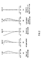
- FIGS. 2A to 2E are views showing various aberrations at a wide
position of the zoom lens according to Embodiment 1 of the present invention.
- FIGS. 3A to 3E are views showing various aberrations at a normal
position of the zoom lens according to Embodiment 1 of the present invention.
- FIGS. 4A to 4E are views showing various aberrations at a tele position
of the zoom lens according to Embodiment 1 of the present invention.
- FIG. 5 is a view showing a configuration of a zoom lens according to
Embodiment 2 of the present invention.
- FIGS. 6A to 6E are views showing various aberrations at a wide
position of the zoom lens according to Embodiment 2 of the present invention.
- FIGS. 7A to 7E are views showing various aberrations at a normal
position of the zoom lens according to Embodiment 2 of the present invention.
- FIGS. 8A to 8E are views showing various aberrations at a tele position
of the zoom lens according to Embodiment 2 of the present invention.
- FIG. 9 is a view showing a configuration of a zoom lens according to
Embodiment 3 of the present invention.
- FIGS. 10A to 10E are views showing various aberrations at a wide
position of the zoom lens according to Embodiment 3 of the present invention.
- FIGS. 11A to 11E are views showing various aberrations at a normal
position of the zoom lens according to Embodiment 3 of the present invention.
- FIGS. 12A to 12E are views showing various aberrations at a tele
position of the zoom lens according to Embodiment 3 of the present invention.
- FIG. 13 is a view showing a configuration of a zoom lens according to
Embodiment 4 of the present invention.
- FIGS. 14A to 14E are views showing various aberrations at a wide
position of the zoom lens according to Embodiment 4 of the present invention.
- FIGS. 15A to 15E are views showing various aberrations at a normal
position of the zoom lens according to Embodiment 4 of the present invention.
- FIGS. 16A to 16E are views showing various aberrations at a tele
position of the zoom lens according to Embodiment 4 of the present invention.
- FIG. 17 is a view showing a configuration of a video camera according to
Embodiment 5 of the present invention.
-
DESCRIPTION OF THE INVENTION
-
Hereinafter, the present invention will be described by way of
illustrative embodiments with reference to the drawings.
[Embodiment 1]
-
FIG. 1 is a view showing the arrangement of a zoom lens according to
Embodiment 1 of the present invention.
-
As shown in FIG. 1, the zoom lens has a structure in which a first lens
group 11, a second lens group 12, a third lens group 13, a fourth lens group 14,
and a glass plate 15 are arranged from an object side (left side in FIG. 1) to an
image plane 16 side (right side in FIG. 1) in this order. Here, the glass
plate 15 is equivalent optically to a crystal filter, a face plate of an imaging
device, etc.
-
The first lens group 11 has positive refracting power, and is fixed with
respect to the image plane 16 even when varying power and focusing. The
second lens group 12 has negative refracting power and varies power by moving
along an optical axis. The third lens group 13 has positive refracting power,
and is fixed with respect to the image plane 16 when varying power and
focusing. The fourth lens group 14 has positive refracting power, and moves
along the optical axis so that the image plane 16 varied by the movement of the
second lens group 12 and the movement of the object to be imaged is kept at a
predetermined position from a reference plane, thereby moving an image and
adjusting the focus thereof at the same time in accordance with variable power.
-
The first lens group 11 is composed of a negative lens 1a, a positive lens
1b, and a positive meniscus lens 1c arranged from the object side in this order,
in which the positive meniscus lens 1c has a convex surface on the object side.
The second lens group 12 is composed of a negative lens 2a, and a cemented
lens of a double-concave lens 2b and a positive lens 2c, which are arranged from
the object side in this order, in which at least one of the surfaces of the foregoing
lenses is aspherical. The third lens group 13 is composed of a positive lens 3a
and a negative plastic lens 3b arranged from the object side in this order, in
which at least one of the surfaces of these lenses is aspherical. The fourth lens
group 14 is a cemented lens composed of a negative plastic lens 4a and a
positive plastic lens 4b that are arranged from the object side in this order, in
which at least one of the surfaces of these lenses is aspherical.
-
In the zoom lens according to the present embodiment, the following
expression (71) is satisfied:
5 < |(fp1+fp2+fp3)/fw| < 12
where fp1 represents a focal length of the negative plastic lens 3b of the third
lens group 13, fp2 represents a focal length of the negative plastic lens 4a of the
fourth lens group 14, fp3 represents a focal length of the positive plastic lens 4b
of the fourth lens group 14, and fw represents a combined focal length of the
entire system at a wide position.
-
With such a configuration that satisfies the expression (71), changes in
refractive indices of the plastic lens materials caused by temperature changes
can be canceled, whereby a deviation of the image plane position can be
decreased. Generally, as properties of a plastic material, a refractive index
thereof decreases as the temperature rises and increases as the temperature
falls, and the plastic material swells as the temperature rises and shrinks as
the temperature falls. In other words, if |(fp1+fp2+fp3)/fw| is not more than
the lower limit of the expression (71), a negative-lens tendency increases in the
combined focal length of the focal length fp1 of the negative plastic lens 3b of
the third lens group 13, and the focal length fp2 of the negative plastic lens 4a
and the focal length fp3 of the positive plastic lens 4b of the fourth lens group
14, and with a temperature rise, the image plane position is deviated farthest
on the object side at the wide position. On the contrary, with a temperature
fall, the image plane position is deviated significantly toward the image plane
side at the wide position. This causes a phenomenon in which the fourth lens
group 14 moving along the optical axis within a certain moving range so as to
keep the image plane at a predetermined position from a reference surface is
incapable of doing so as long as it moves within the foregoing moving range,
thereby resulting in defocusing. On the other hand, if |(fp1+fp2+fp3)/fw| is
not less than the upper limit of the expression (71), a positive-lens tendency
increases in the combined focus length of the focus length fp1 of the negative
plastic lens 3b of the third lens group 13 and the focus length fp2 of the
negative plastic lens 4a and the focus length fp3 of the positive plastic lens 4b of
the fourth lens group 14, and with a temperature rise, the image plane position
is deviated farthest on the image plane side at the normal position. Therefore,
this also results in defocusing.
-
Furthermore, in the zoom lens of the present embodiment, the following
expression (72) is satisfied.
7 < |(fp1+fp2+fp3)/fw| < 10.5
-
With such a configuration of the zoom lens that satisfies the expression
(72) above, changes in refractive indices of the plastic lens materials caused by
temperature changes are canceled, resulting in substantially no deviation of the
image plane position occurring.
-
Furthermore, in the zoom lens according to the present embodiment,
the following expressions (73) to (76) desirably are satisfied:
9 < f1/fw < 11
1 < |f2/fw| < 2
4.5 < f3/fw < 6
4.5 < f4/fw < 6.5
where f1 represents a combined focal length of the first lens group 11, f2
represents a combined focal length of the second lens group 12, f3 represents a
combined focal length of the third lens group 13, and f4 represents a combined
focal length of the fourth lens group 14.
-
In the case where the expressions (73) to (76) are satisfied, the zoom
lens is configured to be compact, with aberration performances excellently
adjusted.
-
If f1/fw is not more than the lower limit of the expression (73), the first
lens group 11 has an excessive refracting power, which makes it difficult to
correct a spherical aberration at the side of the long focal length and an off-axis
coma-aberration. Besides, if f1/fw is not less than the upper limit of the
expression (73), the length of the entire lens increases, which makes it difficult
to make the zoom lens compact.
-
If |f2/fw| is not more than the lower limit of the expression (74), a
Petzval sum of the entire system increases, so that a field curvature cannot be
corrected. If |f2/fw| is not less than the upper limit of the expression (74), the
Petzval sum decreases, but the length of the entire system increases, which
makes it difficult to make the zoom lens compact.
-
If f3/fw is not more than the lower limit of the expression (75), the
refracting power of the third lens group 13 increases, which makes it impossible
to secure a back-focus that allows a crystal filter or the like to be inserted
therein, and makes it difficult to correct the spherical aberration.
Furthermore, if f3/fw is not less than the upper limit of the expression (75), a
Petzval sum increases, thereby making it difficult to correct a field curvature.
-
If f4/fw is not more than the lower limit of the expression (76), the size
of the entire lens system increases, which makes it difficult to make the zoom
lens compact. Furthermore, if f4/fw is not less than the upper limit of the
expression (76), it is difficult to correct off-axis aberrations both in near
photographing and in long-distance photographing at the same time.
-
Furthermore, in the zoom lens according to the present embodiment,
the following expression (77) desirably is satisfied:
d12×fw < 1.2
where d12 represents a distance between the positive lens 3a and the negative
plastic lens 3b of the third lens group 13.
-
In the case where the expression (77) is satisfied, a chromatic
aberration can be corrected excellently in a zooming range from the wide
position to the tele position. If d12×fw is not less than the upper limit of the
expression (77), the chromatic aberration varies more significantly from the
wide position to the tele position, thereby significantly deteriorating the
performance.
-
In the zoom lens according to the present embodiment, the following
expression (78) desirably is satisfied:
(sag(r1)+sag(r2)+d8)/d8 < 4.5
where
sag (r1) represents a sag amount between the center of an incident
surface of the double-concave lens 2b of the second lens group 12 and a position
where the incident surface of the double-concave lens 2b is brought into contact
with an outgoing surface of the negative lens 2a disposed on the object side in
the second lens group 12,
sag (r2) represents a sag amount between the center and an outer-most
peripheral portion of the outgoing surface of the double-concave lens 2b, and
d8 denotes a thickness of the double-concave lens 2b.
-
With satisfaction of the expression (78), the double-concave lens 2b can
be formed readily, whereby the yield thereof can be improved. If
(sag(r1)+sag(r2)+d8)/d8 is not less than the upper limit of the expression (78),
the ratio of a thickness of the central portion of the lens to an edge thickness of
the peripheral portion of the lens increases, making it difficult to mold a lens.
As a result, the yield is lowered and a low cost of lenses cannot be realized.
-
Furthermore, desirably the zoom lens according to the present
embodiment is configured so that a lens surface closest to the image plane of
the first lens group 11 has a radius of curvature equal to a radius of curvature
of a lens surface closest to the object of the second lens group 12. This
prevents the distance between the surface closest to the image plane of the first
lens group 11 and the surface closest to the object of the second lens group 12
from decreasing with increasing proximity to a lens periphery. This facilitates
the production of a lens barrel.
-
Furthermore, in the zoom lens according to the present embodiment,
the following expression (79) desirably is satisfied:
0.6 < BF/fw < 1.1
where BF represents an air distance between an image-plane-side surface of
the lens closest to the image plane and the image plane.
-
By satisfying the foregoing expression (79), it is possible to ensure a
back-focus necessary for allowing an infrared cut-off filter or a low-pass filter
such as a crystal filter to be inserted. Besides, the back-focus is prevented
from increasing unnecessarily, which makes it possible to provide a compact
zoom lens. If BF/fw is not more than the lower limit of the expression (79), a
distance sufficient for allowing an infrared cut-off filter or a low-pass filter such
as a crystal filter to be inserted cannot be ensured. On the other hand, if
BF/fw is not less than the upper limit of the expression (79), the back-focus
excessively increases, thereby making it impossible to provide a compact zoom
lens.
(Example 1)
-
The following Table 1 shows a specific example of the zoom lens
according to the present embodiment.
| Group | Surface | rd | th | nd | ν | |
| 1 | 1 | 37.31 | 0.80 | 1.80518 | 25.4 |
| 2 | 20.08 | 5.05 | 1.58913 | 61.2 |
| 3 | -277.05 | 0.15 |
| 4 | 18.82 | 2.75 | 1.60311 | 60.7 |
| 5 | 51.75 | variable |
| 2 | 6 | 51.75 | 0.60 | 1.80500 | 39.6 |
| 7 | 4.37 | 2.71 |
| 8* | -8.59 | 0.80 | 1.60602 | 57.8 |
| 9 | 5.51 | 2.20 | 1.80518 | 25.5 |
| 10 | 71.99 | variable |
| 3 | 11* | 8.42 | 3.70 | 1.60602 | 57.8 |
| 12* | -10.17 | 0.20 |
| 13 | -15.57 | 0.60 | 1.58387 | 30.1 |
| 14 | 15.57 | variable |
| 4 | 15* | 9.60 | 0.60 | 1.58387 | 30.1 |
| 16 | 4.64 | 2.70 | 1.49178 | 57.2 |
| 17* | -18.52 | variable |
| 5 | 18 | ∞ | 2.80 | 1.51633 | 64.1 |
| 19 | ∞ | - |
-
In Table 1, rd represents a radius of curvature (mm) of a lens, th
represents a thickness (mm) of a lens or an air distance (mm) between lenses,
nd represents a refractive index of each lens with respect to a d-line, and ν
represents an abbe number of each lens with respect to the d-line. The shape
of an aspherical surface (in Table 1, such a surface is denoted with a mark *
attached beside its reference number) is defined by the following equation (80).
Z = cy 2 1 + 1 - (1 + k) c 2 y 2 + Dy 4 + Ey 6+ Fy 8+ Gy 10
where y represents a height from the optical axis, Z represents a distance
between a point on the aspherical surface at the height y from the optical axis
and a tangent plane of the apex on the aspherical surface, c represents a
curvature at the apex on the aspherical surface, k represents a conical constant,
and D, E, F, and G represent aspherical coefficients.
-
The following Table 2 shows aspherical coefficients of the zoom lens in
the present example.
| Surface | k | D | E | F | G |
| 8 | -11.79950 | -2.20951×10⁻³ | 1.33194×10⁻⁴ | -1.25908×10⁻⁵ | 5.36379×10⁻⁷ |
| 11 | 0.66449 | -3.12933×10⁻⁴ | -2.19407×10⁻⁶ | 2.99348×10⁻⁷ | -5.45227×10⁻⁹ |
| 12 | 0.68418 | 4.94313×10⁻⁴ | 2.82004×10⁻⁶ | 4.37043×10⁻⁷ | -8.94886×10⁻⁹ |
| 15 | -0.87201 | 4.78208×10⁻⁵ | -8.02361×10⁻⁶ | 2.23438×10⁻⁶ | -1.34988×10⁻⁷ |
| 17 | -66.19940 | -1.16522×10⁻³ | 6.85576×10⁻⁵ | -9.23566×10⁻⁷ | -1.35439×10⁻⁷ |
-
The following Table 3 shows an air distance (mm) that is varied by
zooming in the case where an object is positioned at infinity.
| | Wide position | Normal position | Tele position |
| Focal length | 3.010 | 27.036 | 69.075 |
| F No. | 1.688 | 2.551 | 3.378 |
| Angle of view (2ω) | 65.136 | 7.614 | 2.954 |
| th5 | 0.700 | 16.949 | 20.341 |
| th10 | 21.740 | 5.491 | 2.099 |
| th12 | 8.120 | 2.490 | 8.120 |
| th17 | 2.000 | 7.630 | 2.000 |
-
The normal position in Table 3 is where the third lens group 13 is
placed most closely to the fourth lens group 14 In Table 3, Focal length (mm),
F No., and ω (°) represent a focal length, an F number, and an incident angle of
view at a wide position, a normal position, and a tele position of the zoom lens
of the present example.
-
FIGS. 2A to 2E, 3A to 3E, and 4A to 4E show performances regarding
various aberrations at the wide position, the normal position, and the tele
position of the zoom lens shown in the present example, respectively. FIGS.
2A, 3A and 4A show a spherical aberration (mm); FIGS. 2B, 3B and 4B show
astigmatism (mm); FIGS. 2C, 3C and 4C show a distortion aberration (%); FIGS.
2D, 3D and 4D show a longitudinal chromatic aberration (mm); and FIGS. 2E,
3E and 4E show a chromatic aberration of magnification (mm). In FIGS. 2B,
3B and 4B showing astigmatism, a solid line represents a sagittal field
curvature, and a broken line represents a meridional field curvature. In FIGS.
2D, 3D and 4D showing the longitudinal chromatic aberration and FIGS. 2E,
3E and 4E showing the chromatic aberration of magnification, a solid line
represents the values with respect to the d-line, a short broken line represents
the values with respect to an F-line, and a long broken line represents the
values with respect to a C-line. As is apparent from the drawings regarding
these aberrations, the zoom lens of the present example has an excellent
aberration performance.
-
The amount of movement of the image plane position according to a
change in a refractive index of a plastic lens material caused by a temperature
change is 0.9 µm/C° when the object is positioned at infinity and the zooming
position is at the wide position.
[Embodiment 2]
-
FIG. 5 is a view showing the arrangement of a zoom lens according to
Embodiment 2 of the present invention.
-
As shown in FIG. 5, the zoom lens has a structure in which a first lens
group 21, a second lens group 22, a third lens group 23, a fourth lens group 24,
and a glass plate 25 are arranged from an object side (left side in FIG. 5) to an
image plane 26 side (right side in FIG. 5) in this order. Here, the glass
plate 25 is equivalent optically to a crystal filter, a face plate of an imaging
device, etc.
-
The first lens group 21 has positive refracting power, and is fixed with
respect to the image plane 26 even when varying power and focusing. The
second lens group 22 has negative refracting power and varies power by moving
along an optical axis. The third lens group 23 has positive refracting power,
and is fixed with respect to the image plane 26 even when varying power and
focusing. The fourth lens group 24 has positive refracting power, and moves
along the optical axis so that the image plane 26 varied by the movement of the
second lens group 22 and the movement of the object to be imaged is kept at a
predetermined position from a reference plane, thereby moving an image and
adjusting the focus thereof at the same time in accordance with variable power.
-
The first lens group 21 is composed of a negative lens 5a, a positive lens
5b, and a positive meniscus lens 5c arranged from the object side in this order,
in which the positive meniscus lens 5c has a convex surface on the object side.
The second lens group 22 is composed of a negative lens 6a, and a cemented
lens of a double-concave lens 6b and a positive lens 6c, which are arranged from
the object side in this order, in which at least one of the surfaces of the foregoing
lenses is aspherical. The third lens group 23 is composed of a positive lens 7a
and a negative plastic lens 7b arranged from the object side in this order, in
which at least one of the surfaces of these lenses is aspherical. The fourth lens
group 24 is a cemented lens composed of a positive plastic lens 8a and a
negative plastic lens 8b that are arranged from the object side in this order, in
which at least one of the surfaces of these lenses is aspherical.
-
In the zoom lens according to the present embodiment, the following
expression (81) is satisfied:
5 < |(fp1+fp2+fp3)/fw| < 12
where fp1 represents a focal length of the negative plastic lens 7b of the third
lens group 23, fp2 represents a focal length of the positive plastic lens 8a of the
fourth lens group 24, fp3 represents a focal length of the negative plastic lens
8b of the fourth lens group 24, and fw represents a combined focal length of the
entire system at a wide position.
-
With such a configuration that satisfies the expression (81), changes in
refractive indices of the plastic lens materials caused by temperature changes
can be canceled, whereby a deviation of the image plane position can be
decreased. Generally, as properties of a plastic material, a refractive index
thereof decreases as the temperature rises and increases as the temperature
falls, and the plastic material swells as the temperature rises and shrinks as
the temperature falls. In other words, if |(fp1+fp2+fp3)/fw| is not more than
the lower limit of the expression (81), a negative-lens tendency increases in the
combined focal length of the focal length fp1 of the negative plastic lens 7b of
the third lens group 23, and the focal length fp2 of the positive plastic lens 8a
and the focal length fp3 of the negative plastic lens 8b of the fourth lens group
24, and with a temperature rise, the image plane position is deviated farthest
on the object side at the wide position. On the contrary, with a temperature
fall, the image plane position is deviated significantly toward the image plane
side at the wide position. This causes a phenomenon in which the fourth lens
group 24 moving along the optical axis within a certain moving range so as to
keep the image plane at a predetermined position from a reference surface is
incapable of doing so as long as it moves within the foregoing moving range,
thereby resulting in defocusing. On the other hand, if |(fp1+fp2+fp3)/fw| is
not less than the upper limit of the expression (81), a positive-lens tendency
increases in the combined focus length of the focus length fp1 of the negative
plastic lens 7b of the third lens group 23 and the focus length fp2 of the positive
plastic lens 8a and the focus length fp3 of the negative plastic lens 8b of the
fourth lens group 24, and with a temperature rise, the image plane position is
deviated farthest on the image plane side at the normal position. Therefore,
this also results in defocusing.
-
Furthermore, in the zoom lens of the present embodiment, the following
expression (82) is satisfied.
7 < |(fp1+fp2+fp3)/fw| < 10.5
-
With such a configuration of the zoom lens that satisfies the expression
(82) above, changes in refractive indices of the plastic lens materials caused by
temperature changes are canceled, resulting in substantially no deviation of the
image plane position occurring.
-
Furthermore, in the zoom lens according to the present embodiment,
the following expressions (83) to (86) desirably are satisfied:
9 < f1/fw < 11
1 < |f2/fw| < 2
4.5 < f3/fw < 6
4.5 < f4/fw < 6.5
where f1 represents a combined focal length of the first lens group 21, f2
represents a combined focal length of the second lens group 22, f3 represents a
combined focal length of the third lens group 23, and f4 represents a combined
focal length of the fourth lens group 24.
-
In the case where the expressions (83) to (86) are satisfied, the zoom
lens is configured to be compact, with aberration performances excellently
adjusted.
-
If f1/fw is not more than the lower limit of the expression (83), the first
lens group 21 has an excessive refracting power, which makes it difficult to
correct a spherical aberration at the side of the long focal length and an off-axis
coma-aberration. Besides, if f1/fw is not less than the upper limit of the
expression (83), the full length of the lens increases, which makes it difficult to
make the zoom lens compact.
-
If |f2/fw| is not more than the lower limit of the expression (84), a
Petzval sum of the entire system increases, so that a field curvature cannot be
corrected. If |f2/fw| is not less than the upper limit of the expression (84), the
Petzval sum decreases, but the length of the entire system increases, which
makes it difficult to make the zoom lens compact.
-
If f3/fw is not more than the lower limit of the expression (85), the
refracting power of the third lens group 23 increases, which makes it impossible
to secure a back-focus that allows a crystal filter or the like to be inserted
therein, and makes it difficult to correct the spherical aberration.
Furthermore, if f3/fw is not less than the upper limit of the expression (85), a
Petzval sum increases, thereby making it difficult to correct a field curvature.
-
If f4/fw is not more than the lower limit of the expression (86), the size
of the entire lens system increases, which makes it difficult to make the zoom
lens compact. Furthermore, if f4/fw is not less than the upper limit of the
expression (86), it is difficult to correct off-axis aberrations both in near
photographing and in long-distance photographing at the same time.
-
Furthermore, in the zoom lens according to the present embodiment,
the following expression (87) desirably is satisfied:
d12×fW < 1.2
where d12 represents a distance between the positive lens 7a and the negative
plastic lens 7b of the third lens group 23.
-
In the case where the expression (87) is satisfied, a chromatic
aberration can be corrected excellently in a zooming range from the wide
position to the tele position. If d12×fw is not less than the upper limit of the
expression (87), the chromatic aberration significantly varies from the wide
position to the tele position, thereby significantly deteriorating the
performance.
-
In the zoom lens according to the present embodiment, the following
expression (88) desirably is satisfied:
(sag(r1)+sag(r2)+d8)/d8 < 4.5
where
sag (r1) represents a sag amount between the center of an incident
surface of the double-concave lens 6b of the second lens group 22 and a position
where the incident surface of the double-concave lens 6b is brought into contact
with an outgoing surface of the negative lens 6a disposed on the object side in
the second lens group 22,
sag (r2) represents a sag amount between the center and an outer-most
peripheral portion of the outgoing surface of the double-concave lens 6b, and,
d8 denotes a thickness of the double-concave lens 6b.
-
With satisfaction of the expression (88), the double-concave lens 6b can
be formed readily, whereby the yield thereof can be improved. If
(sag(r1)+sag(r2)+d8)/d8 is not less than the upper limit of the expression (88),
the ratio of a thickness of the central portion of the lens to an edge thickness of
the peripheral portion of the lens increases, making it difficult to mold a lens.
As a result, the yield is lowered and a low cost of lenses cannot be realized.
-
Furthermore, desirably the zoom lens according to the present
embodiment is configured so that a lens surface closest to the image plane of
the first lens group 21 has a radius of curvature equal to a radius of curvature
of a lens surface closest to the object of the second lens group 22. This
prevents the distance between the surface closest to the image plane of the first
lens group 21 and the surface closest to the object of the second lens group 22
from decreasing with increasing proximity to a lens periphery. This facilitates
the production of a lens barrel.
-
Furthermore, in the zoom lens according to the present embodiment,
the following expression (89) desirably is satisfied:
0.6 < BF/fw < 1.1
where BF represents an air distance between the image-plane-side surface of
the lens closest to the image plane and the image plane.
-
By satisfying the foregoing expression (89), it is possible to ensure a
back-focus necessary for allowing an infrared cut-off filter or a low-pass filter
such as a crystal filter to be inserted. Besides, the back-focus is prevented
from increasing unnecessarily, which makes it possible to provide a compact
zoom lens. If BF/fw is not more than the lower limit of the expression (89), a
distance sufficient for allowing an infrared cut-off filter or a low-pass filter such
as a crystal filter to be inserted cannot be ensured. On the other hand, if
BF/fw is not less than the upper limit of the expression (89), the back-focus
excessively increases, thereby making it impossible to provide a compact zoom
lens.
(Example 2)
-
The following Table 4 shows a specific example of the zoom lens
according to the present embodiment.
| Group | Surface | rd | th | nd | ν | |
| 1 | 1 | 38.45 | 0.90 | 1.80518 | 25.4 |
| 2 | 20.52 | 5.10 | 1.58913 | 61.2 |
| 3 | -183.44 | 0.15 |
| 4 | 18.54 | 2.70 | 1.60311 | 60.7 |
| 5 | 46.73 | variable |
| 2 | 6 | 46.73 | 0.60 | 1.80500 | 39.6 |
| 7 | 4.34 | 2.75 |
| 8* | -8.67 | 1.00 | 1.60602 | 57.8 |
| 9 | 5.50 | 2.30 | 1.80518 | 25.5 |
| 10 | 65.80 | variable |
| 3 | 11* | 7.74 | 4.00 | 1.51450 | 63.5 |
| 12* | -8.86 | 0.30 |
| 13 | -16.83 | 0.60 | 1.58387 | 30.1 |
| 14 | 19.85 | variable |
| 4 | 15* | 16.72 | 2.80 | 1.54324 | 53.1 |
| 16 | -4.90 | 0.70 | 1.58387 | 30.1 |
| 17* | -13.59 | variable |
| 5 | 18 | ∞ | 2.80 | 1.51633 | 64.1 |
| 19 | ∞ | - |
-
In Table 4, rd represents a radius of curvature (mm) of a lens, th
represents a thickness (mm) of a lens or an air distance (mm) between lenses,
nd represents a refractive index of each lens with respect to a d-line, and ν
represents an abbe number of each lens with respect to the d-line. The shape
of an aspherical surface (in Table 4, such a surface is denoted with a mark *
attached beside its reference number) is defined by the aforementioned
equation (80).
-
The following Table 5 shows aspherical coefficients of the zoom lens in
the present example.
| Surface | k | D | E | F | G |
| 8 | -11.79950 | -2.20951×10⁻³ | 1.33194×10⁻⁴ | -1.25908×10⁻⁵ | 5.36379×10⁻⁷ |
| 11 | 0.17661 | -2.65165×10⁻⁴ | 6.26544×10⁻⁷ | 1.06422×10⁻⁷ | 1.35942×10⁻¹⁰ |
| 12 | 0.10560 | 6.23500×10⁻⁴ | 4.29405×10⁻⁶ | 6.88052×10⁻⁸ | 2.80861×10⁻¹⁰ |
| 15 | -30.31690 | 5.21270×10⁻⁴ | -9.10874×10⁻⁶ | -8.92635×10⁻⁷ | 3.69895×10⁻⁸ |
| 17 | 0.12809 | -1.23533×10⁻⁴ | 2.35203×10⁻⁵ | -2.46202×10⁻⁶ | 9.65532×10⁻⁸ |
-
The following Table 6 shows an air distance (mm) that is varied by
zooming in the case where an object is positioned at infinity.
| | Wide position | Normal position | Tele position |
| Focal length | 3.010 | 25.627 | 68.915 |
| F No. | 1.688 | 2.490 | 3.355 |
| Angle of view (2ω) | 65.136 | 8.060 | 2.960 |
| th5 | 0.700 | 16.925 | 20.316 |
| th10 | 20.740 | 4.515 | 1.124 |
| th12 | 8.120 | 2.629 | 8.120 |
| th17 | 2.000 | 7.491 | 2.000 |
-
The normal position in Table 6 is where the third lens group 23 is
placed most closely to the fourth lens group 24 In Table 6, Focal length (mm),
F No., and ω (°) represent a focal length, an F number, and an incident angle of
view at a wide position, a normal position, and a tele position of the zoom lens
of the present example.
-
FIGS. 6A to 6E, 7A to 7E, and 8A to 8E show performances regarding
various aberrations at the wide position, the normal position, and the tele
position of the zoom lens shown in the present example, respectively. FIGS.
6A, 7A and 8A show a spherical aberration (mm); FIGS. 6B, 7B and 8B show
astigmatism (mm); FIGS. 6C, 7C and 8C show a distortion aberration (%); FIGS.
6D, 7D and 8D show a longitudinal chromatic aberration (mm); and FIGS. 6E,
7E and 8E show a chromatic aberration of magnification (mm). In FIGS. 6B,
7B and 8B showing astigmatism, a solid line represents a sagittal field
curvature, and a broken line represents a meridional field curvature. In FIGS.
6D, 7D and 8D showing the longitudinal chromatic aberration and FIGS. 6E,
7E and 8E showing the chromatic aberration of magnification, a solid line
represents values with respect to the d-line, a short broken line represents
values with respect to an F-line, and a long broken line represents values with
respect to a C-line. As is apparent from the drawings regarding these
aberrations, the zoom lens of the present example has an excellent aberration
performance.
-
A movement amount of the image plane position according to a change
in a refractive index of a plastic lens material caused by a temperature change
is 1.0 µm/C° when the object is positioned at infinity and the zooming position is
at the wide position.
[Embodiment 3]
-
FIG. 9 is a view showing the arrangement of a zoom lens according to
Embodiment 3 of the present invention.
-
As shown in FIG. 9, the zoom lens has a structure in which a first lens
group 31, a second lens group 32, a third lens group 33, a fourth lens group 34,
and a glass plate 35 are arranged from an object side (left side in FIG. 9) to an
image plane 36 side (right side in FIG. 9) in this order. Here, the glass
plate 35 is equivalent optically to a crystal filter or a face plate of an imaging
device, etc.
-
The first lens group 31 has positive refracting power, and is fixed with
respect to the image plane 36 even when varying power and focusing. The
second lens group 32 has negative refracting power and varies power by moving
along an optical axis. The third lens group 33 has positive refracting power,
and is fixed with respect to the image plane 36 even when varying power and
focusing. The fourth lens group 34 has positive refracting power, and moves
along the optical axis so that the image plane 36 varied by the movement of the
second lens group 32 and the movement of the object to be imaged is kept at a
predetermined position from a reference plane, thereby moving an image and
adjusting the focus thereof at the same time in accordance with variable power.
-
The first lens group 31 is composed of a negative lens 9a, a positive lens
9b, and a positive meniscus lens 9c arranged from the object side in this order,
in which the positive meniscus lens 9c has a convex surface on the object side.
The second lens group 32 is composed of a negative lens 10a, and a cemented
lens of a double-concave lens 10b and a positive lens 10c, which are arranged
from the object side in this order, in which at least one of the surfaces of the
foregoing lenses is aspherical. The third lens group 33 is composed of a
positive lens 11a and a negative plastic lens 11b arranged from the object side
in this order, in which at least one of the surfaces of these lenses is aspherical.
The fourth lens group 34 is composed of a negative plastic lens 12a and a
positive plastic lens 12b that are arranged from the object side in this order, in
which at least one of the surfaces of these lenses is aspherical.
-
In the zoom lens according to the present embodiment, the following
expression (90) desirably is satisfied:
5 < |(fp1+fp2+fp3)/fw| < 12
where fp1 represents a focal length of the negative plastic lens 11b of the third
lens group 33, fp2 represents a focal length of the negative plastic lens 12a of
the fourth lens group 34, fp3 represents a focal length of the positive plastic
lens 12b of the fourth lens group 34, and fw represents a combined focal length
of the entire system at a wide position.
-
With a configuration that satisfies the expression (90), changes in
refractive indices of the plastic lens materials caused by temperature changes
can be canceled, whereby a deviation of the image plane position can be
decreased. Generally, as properties of a plastic material, a refractive index
thereof decreases as the temperature rises and increases as the temperature
falls, and the plastic material swells as the temperature rises and shrinks as
the temperature falls. In other words, if |(fp1+fp2+fp3)/fw| is not more than
the lower limit of the expression (90), a negative-lens tendency increases in the
combined focal length of the focal length fp1 of the negative plastic lens11b of
the third lens group 33, and the focal length fp2 of the negative plastic lens 12a
and the focal length fp3 of the positive plastic lens 12b of the fourth lens group
34, and with a temperature rise, the image plane position is deviated farthest
on the object side at the wide position. On the contrary, with a temperature
fall, the image plane position is deviated significantly toward the image plane
side at the wide position. This causes a phenomenon in which the fourth lens
group 34 moving along the optical axis within a certain moving range so as to
keep the image plane at a predetermined position from a reference surface is
incapable of doing so as long as it moves within the foregoing moving range,
thereby resulting in defocusing. On the other hand, if |(fp1+fp2+fp3)/fw| is
not less than the upper limit of the expression (90), a positive-lens tendency
increases in the combined focus length of the focus length fp1 of the negative
plastic lens 11b of the third lens group 33 and the focus length fp2 of the
negative plastic lens 12a and the focus length fp3 of the positive plastic lens 12b
of the fourth lens group 34, and with a temperature rise, the image plane
position is deviated farthest on the image plane side at the normal position.
Therefore, this also results in defocusing.
-
Furthermore, in the zoom lens of the present embodiment, the following
expression (91) desirably is satisfied.
7 < |(fp1+fp2+fp3)/fw| < 10.5
-
By configuring the zoom lens so that the expression (91) above is
satisfied, changes in refractive indices of the plastic lens materials caused by
temperature changes are canceled, resulting in substantially no deviation of the
image plane position occurring.
-
Furthermore, in the zoom lens according to the present embodiment,
the following expressions (92) to (95) desirably are satisfied:
9 < f1/fw < 11
1 < lf2/fw| < 2
4.5 < f3/fw < 6
4.5 < f4/fw < 6.5
where f1 represents a combined focal length of the first lens group 31, f2
represents a combined focal length of the second lens group 32, f3 represents a
combined focal length of the third lens group 33, and f4 represents a combined
focal length of the fourth lens group 34.
-
In the case where the expressions (92) to (95) are satisfied, the zoom
lens is configured to be compact, with aberration performances excellently
adjusted.
-
If f1/fw is not more than the lower limit of the expression (92), the first
lens group 31 has an excessive refracting power, which makes it difficult to
correct a spherical aberration at the side of the long focal length and an off-axis
coma-aberration. Besides, if f1/fw is not less than the upper limit of the
expression (92), the full length of the lens increases, which makes it difficult to
make the zoom lens compact.
-
If |f2/fw| is not more than the lower limit of the expression (93), a
Petzval sum of the entire system increases, so that a field curvature cannot be
corrected. If |f2/fw| is not less than the upper limit of the expression (93), the
Petzval sum decreases, but the length of the entire system increases, which
makes it difficult to make the zoom lens compact.
-
If f3/fw is not more than the lower limit of the expression (94), the
refracting power of the third lens group 33 increases, which makes it impossible
to secure a back-focus that allows a crystal filter or the like to be inserted
therein, and makes it difficult to correct the spherical aberration.
Furthermore, if f3/fw is not less than the upper limit of the expression (94), a
Petzval sum increases, thereby making it difficult to correct a field curvature.
-
If f4/fw is not more than the lower limit of the expression (95), the size
of the entire lens system increases, which makes it difficult to make the zoom
lens compact. Furthermore, if f4/fw is not less than the upper limit of the
expression (95), it is difficult to correct off-axis aberrations both in near
photographing and in long-distance photographing at the same time.
-
Furthermore, in the zoom lens according to the present embodiment,
the following expression (96) desirably is satisfied:
d12×fw < 1.2
where d12 represents a distance between the positive lens 11a and the negative
plastic lens 11b of the third lens group 33.
-
In the case where the expression (96) is satisfied, a chromatic
aberration can be corrected excellently in a zooming range from the wide
position to the tele position. If d12×fw is not less than the upper limit of the
expression (96), the chromatic aberration significantly varies from the wide
position to the tele position, thereby significantly deteriorating the
performance.
-
In the zoom lens according to the present embodiment, the following
expression (97) desirably is satisfied:
(sag(r1)+sag(r2)+d8)/d8 < 4.5
where
sag (r1) represents a sag amount between the center of an incident
surface of the double-concave lens 10b of the second lens group 32 and a
position where the incident surface of the double-concave lens 10b is brought
into contact with an outgoing surface of the negative lens 10a disposed on the
object side in the second lens group 32,
sag (r2) represents a sag amount between the center and an outer-most
peripheral portion of the outgoing surface of the double-concave lens 10b, and,
d8 denotes a thickness of the double-concave lens 10b.
-
With satisfaction of the expression (97), the double-concave lens 10b can
be formed readily, whereby the yield thereof can be improved. If
(sag(r1)+sag(r2)+d8)/d8 is not less than the upper limit of the expression (97),
the ratio of a thickness of the central portion of the lens to an edge thickness of
the peripheral portion of the lens increases, making it difficult to mold a lens.
As a result, the yield is lowered and a low cost of lenses cannot be realized.
-
Furthermore, desirably the zoom lens according to the present
embodiment is configured so that a lens surface closest to the image plane of
the first lens group 31 has a radius of curvature equal to a radius of curvature
of a lens surface closest to the object of the second lens group 32. This
prevents the distance between the surface closest to the image plane of the first
lens group 31 and the surface closest to the object of the second lens group 32
from decreasing with increasing proximity to a lens periphery. This facilitates
the production of a lens barrel.
-
Furthermore, in the zoom lens according to the present embodiment,
the following expression (98) desirably is satisfied:
0.6 < BF/fw < 1.1
where BF represents an air distance between the image-plane-side surface of
the lens closest to the image plane and the image plane.
-
By satisfying the foregoing expression (98), it is possible to ensure a
back-focus necessary for allowing an infrared cut-off filter or a low-pass filter
such as a crystal filter to be inserted. Besides, the back-focus is prevented
from increasing unnecessarily, which makes it possible to provide a compact
zoom lens. If BF/fw is not more than the lower limit of the expression (98), a
distance sufficient for allowing an infrared cut-off filter or a low-pass filter such
as a crystal filter to be inserted cannot be ensured. On the other hand, if
BF/fw is not less than the upper limit of the expression (98), the back-focus
excessively increases, thereby making it impossible to provide a compact zoom
lens.
(Example 3)
-
The following Table 7 shows a specific example of the zoom lens
according to the present embodiment.
| Group | Surface | rd | th | nd | ν | |
| 1 | 1 | 39.25 | 0.80 | 1.80518 | 25.4 |
| 2 | 20.47 | 5.10 | 1.58913 | 61.2 |
| 3 | -171.50 | 0.20 |
| 4 | 18.24 | 2.75 | 1.60311 | 60.7 |
| 5 | 45.42 | variable |
| 2 | 6 | 45.42 | 0.60 | 1.80500 | 39.6 |
| 7 | 4.30 | 2.70 |
| 8* | -8.58 | 0.90 | 1.60602 | 57.8 |
| 9 | 5.51 | 2.30 | 1.80518 | 25.5 |
| 10 | 73.39 | variable |
| 3 | 11* | 8.63 | 3.80 | 1.60602 | 57.8 |
| 12* | -9.39 | 0.20 |
| 13 | -13.38 | 0.70 | 1.58387 | 30.1 |
| 14 | 16.47 | variable |
| 4 | 15* | 10.28 | 1.00 | 1.58387 | 30.1 |
| 16 | 6.00 | 0.30 |
| 17 | 5.70 | 2.80 | 1.49178 | 57.2 |
| 18* | -22.98 | variable |
| 5 | 19 | ∞ | 2.80 | 1.51633 | 64.1 |
| 20 | ∞ |
-
In Table 7, rd represents a radius of curvature (mm) of a lens, th
represents a thickness (mm) of a lens or an air distance (mm) between lenses,
nd represents a refractive index of each lens with respect to a d-line, and ν
represents an abbe number of each lens with respect to the d-line. The shape
of an aspherical surface (in Table 7, such a surface is denoted with a mark *
attached beside its reference number) is defined by the aforementioned
equation (80).
-
The following Table 8 shows aspherical coefficients of the zoom lens in
the present example.
| Surface | k | D | E | F | G |
| 8 | -11.79950 | -2.20951×10⁻³ | 1.33194×10⁻⁴ | -1.25908×10⁻⁵ | 5.36379×10⁻⁷ |
| 11 | 0.69201 | -2.54836×10⁻⁴ | -3.96421×10⁻⁶ | 3.21063×10⁻⁷ | -6.30435×10⁻⁹ |
| 12 | 0.49478 | 5.43522×10⁻⁴ | 3.05097×10⁻⁶ | 2.39230×10⁻⁷ | -4.48837×10⁻⁹ |
| 17 | -0.44842 | 9.83921×10⁻⁵ | 6.00419×10⁻⁶ | 1.99002×10⁻⁶ | -9.74119×10⁻⁸ |
| 18 | -108.49600 | -6.70268×10⁻⁴ | 8.89076×10⁻⁵ | -1.15393×10⁻⁶ | -4.33822×10⁻⁸ |
-
The following Table 9 shows an air distance (mm) that is varied by
zooming in the case where an object is positioned at infinity.
| | Wide position | Normal position | Tele position |
| Focal length | 3.010 | 26.710 | 69.512 |
| F No. | 1.688 | 2.485 | 3.385 |
| Angle of view (2ω) | 65.136 | 7.730 | 2.948 |
| th5 | 0.700 | 16.950 | 20.341 |
| th10 | 20.740 | 4.412 | 1.099 |
| th12 | 8.120 | 2.538 | 8.120 |
| th17 | 2.000 | 7.582 | 2.000 |
-
The normal position in Table 9 is where the third lens group 33 is
placed most closely to the fourth lens group 34 In Table 9, Focal length (mm),
F No., and ω (°) represent a focal length, an F number, and an incident angle of
view at a wide position, a normal position, and a tele position of the zoom lens
of the present example.
-
FIGS. 10A to 10E, 11A to 11E, and 12A to 12E show performances
regarding various aberrations at the wide position, the normal position, and the
tele position of the zoom lens shown in the present example, respectively.
FIGS. 10A, 11A and 12A show a spherical aberration (mm); FIGS. 10B, 11B and
12B show astigmatism (mm); FIGS. 10C, 11C and 12C show a distortion
aberration (%); FIGS. 10D, 11D and 12D show a longitudinal chromatic
aberration (mm); and FIGS. 10E, 11E and 12E show a chromatic aberration of
magnification (mm). In FIGS. 10B, 11B and 12B showing astigmatism, a solid
line represents a sagittal field curvature, and a broken line represents a
meridional field curvature. In FIGS. 10D, 11D and 12D showing the
longitudinal chromatic aberration and FIGS. 10E, 11E and 12E showing the
chromatic aberration of magnification, a solid line represents values with
respect to the d-line, a short broken line represents values with respect to an
F-line, and a long broken line represents values with respect to a C-line. As is
apparent from the drawings regarding these aberrations, the zoom lens of the
present example has an excellent aberration performance.
-
A movement amount of the image plane position according to a change
in a refractive index of a plastic lens material caused by a temperature change
is 1.2 µm/C° when the object is positioned at infinity and the zooming position is
at the wide position.
[Embodiment 4]
-
FIG. 13 is a view showing the arrangement of a zoom lens according to
Embodiment 4 of the present invention.
-
As shown in FIG. 13, the zoom lens has a structure in which a first lens
group 41, a second lens group 42, a third lens group 43, a fourth lens group 44,
and a glass plate 45 are arranged from an object side (left side in FIG. 13) to an
image plane 46 side (right side in FIG. 13) in this order. Here, the glass
plate 45 is equivalent optically to a crystal filter or a face plate of an imaging
device, etc.
-
The first lens group 41 has positive refracting power, and is fixed with
respect to the image plane 46 even when varying power and focusing. The
second lens group 42 has negative refracting power and varies power by moving
along an optical axis. The third lens group 43 has positive refracting power,
and is fixed with respect to the image plane 46 even when varying power and
focusing. The fourth lens group 44 has positive refracting power, and moves
along the optical axis so that the image plane 46 varied by the movement of the
second lens group 42 and the movement of the object to be imaged is kept at a
predetermined position from a reference plane, thereby moving an image and
adjusting the focus thereof at the same time in accordance with variable power.
-
The first lens group 41 is composed of a negative lens 13a, a positive
lens 13b, and a positive meniscus lens 13c arranged from the object side in this
order, in which the positive meniscus lens 13c has a convex surface on the object
side. The second lens group 42 is composed of a negative lens 14a, and a
cemented lens of a double-concave lens 14b and a positive lens 14c, which are
arranged from the object side in this order, in which at least one of the surfaces
of the foregoing lenses is aspherical. The third lens group 43 is a cemented
lens composed of a positive lens 15a and a negative plastic lens 15b arranged
from the object side in this order, in which at least one of the surfaces of these
lenses is aspherical. The fourth lens group 44 is a cemented lens composed of
a negative plastic lens 16a and a positive plastic lens 16b that are arranged
from the object side in this order, in which at least one of the surfaces of these
lenses is aspherical.
-
In the zoom lens according to the present embodiment, the following
expression (99) is satisfied:
5 < |(fp1+fp2+fp3)/fw| < 12
where fp1 represents a focal length of the negative plastic lens 15b of the third
lens group 43, fp2 represents a focal length of the negative plastic lens 16a of
the fourth lens group 44, fp3 represents a focal length of the positive plastic
lens 16b of the fourth lens group 44, and fw represents a combined focal length
of the entire system at a wide position.
-
With such a configuration that satisfies the expression (99), changes in
refractive indices of the plastic lens materials caused by temperature changes
can be canceled, whereby a deviation of the image plane position can be
decreased. Generally, as properties of a plastic material, a refractive index
thereof decreases as the temperature rises and increases as the temperature
falls, and the plastic material swells as the temperature rises and shrinks as
the temperature falls. In other words, if |(fp1+fp2+fp3)/fw| is not more than
the lower limit of the expression (99), a negative-lens tendency increases in the
combined focal length of the focal length fp1 of the negative plastic lens15b of
the third lens group 43, and the focal length fp2 of the negative plastic lens 16a
and the focal length fp3 of the positive plastic lens 16b of the fourth lens group
44, and with a temperature rise, the image plane position is deviated farthest
on the object side at the wide position. On the contrary, with a temperature
fall, the image plane position is deviated significantly toward the image plane
side at the wide position. This causes a phenomenon in which the fourth lens
group 44 moving along the optical axis within a certain moving range so as to
keep the image plane at a predetermined position from a reference surface is
incapable of doing so as long as it moves within the foregoing moving range,
thereby resulting in defocusing. On the other hand, if |(fp1+fp2+fp3)/fw| is
not less than the upper limit of the expression (99), a positive-lens tendency
increases in the combined focus length of the focus length fp1 of the negative
plastic lens 15b of the third lens group 43 and the focus length fp2 of the
negative plastic lens 16a and the focus length fp3 of the positive plastic lens 16b
of the fourth lens group 44, and with a temperature rise, the image plane
position is deviated farthest on the image plane side at the normal position.
Therefore, this also results in defocusing.
-
Furthermore, in the zoom lens of the present embodiment, the following
expression (100) desirably is satisfied.
7 < |(fp1+fp2+fp3)/fw| < 10.5
-
With such a configuration of the zoom lens that satisfies the expression
(100) above, changes in refractive indices of the plastic lens materials caused by
temperature changes are canceled, resulting in substantially no deviation of the
image plane position occurring.
-
Furthermore, in the zoom lens according to the present embodiment,
the following expressions (101) to (104) desirably are satisfied:
9 < f1/fw < 11
1 < |f2/fw| < 2
4.5 < f3/fw < 6
4.5 < f4/fw < 6.5
where f1 represents a combined focal length of the first lens group 41, f2
represents a combined focal length of the second lens group 42, f3 represents a
combined focal length of the third lens group 43, and f4 represents a combined
focal length of the fourth lens group 44.
-
In the case where the expressions (101) to (104) are satisfied, the zoom
lens is configured to be compact, with aberration performances excellently
adjusted.
-
If f1/fw is not more than the lower limit of the expression (101), the first
lens group 41 has an excessive refracting power, which makes it difficult to
correct a spherical aberration at the side of the long focal length and an off-axis
coma-aberration. Besides, if f1/fw is not less than the upper limit of the
expression (101), the full length of the lens increases, which makes it difficult to
make the zoom lens compact.
-
If |f2/fw| is not more than the lower limit of the expression (102), a
Petzval sum of the entire system increases, so that a field curvature cannot be
corrected. If |f2/fw| is not less than the upper limit of the expression (102),
the Petzval sum decreases, but the length of the entire system increases, which
makes it difficult to make the zoom lens compact.
-
If f3/fw is not more than the lower limit of the expression (103), the
refracting power of the third lens group 43 increases, which makes it impossible
to secure a back-focus that allows a crystal filter or the like to be inserted
therein, and makes it difficult to correct the spherical aberration.
Furthermore, if f3/fw is not less than the upper limit of the expression (103), a
Petzval sum increases, thereby making it difficult to correct a field curvature.
-
If f4/fw is not more than the lower limit of the expression (104), the size
of the entire lens system increases, which makes it difficult to make the zoom
lens compact. Furthermore, if f4/fw is not less than the upper limit of the
expression (104), it is difficult to correct off-axis aberrations both in near
photographing and in long-distance photographing at the same time.
-
In the zoom lens according to the present embodiment, the following
expression (105) desirably is satisfied:
(sag(r1)+sag(r2)+d8)/d8 < 4.5
where
sag (r1) represents a sag amount between the center of an incident
surface of the double-concave lens 14b of the second lens group 42 and a
position where the incident surface of the double-concave lens 14b is brought
into contact with an outgoing surface of the negative lens 14a disposed on the
object side in the second lens group 42,
sag (r2) represents a sag amount between the center and an outer-most
peripheral portion of the outgoing surface of the double-concave lens 14b, and
d8 denotes a thickness of the double-concave lens 14b.
-
With satisfaction of the expression (105), the double-concave lens 14b
can be formed readily, whereby the yield thereof can be improved. If
(sag(rl)+sag(r2)+d8)/d8 is not less than the upper limit of the expression (105),
the ratio of a thickness of the central portion of the lens to an edge thickness of
the peripheral portion of the lens increases, making it difficult to mold a lens.
As a result, the yield is lowered and a low cost of lenses cannot be realized.
-
Furthermore, desirably the zoom lens according to the present
embodiment is configured so that a lens surface closest to the image plane of
the first lens group 41 has a radius of curvature equal to a radius of curvature
of a lens surface closest to the object of the second lens group 42. This
prevents the distance between the surface closest to the image plane of the first
lens group 41 and the surface closest to the object of the second lens group 42
from decreasing with increasing proximity to a lens periphery. This facilitates
the production of a lens barrel.
-
Furthermore, in the zoom lens according to the present embodiment,
the following expression (106) desirably is satisfied:
0.6 < BF/fw < 1.1
where BF represents an air distance between the image-plane-side surface of
the lens closest to the image plane of lens and the image plane.
-
By satisfying the foregoing expression (106), it is possible to ensure a
back-focus necessary for allowing an infrared cut-off filter or a low-pass filter
such as a crystal filter to be inserted. Besides, the back-focus is prevented
from increasing unnecessarily, which makes it possible to provide a compact
zoom lens. If BF/fw is not more than the lower limit of the expression (106), a
distance sufficient for allowing an infrared cut-off filter or a low-pass filter such
as a crystal filter to be inserted cannot be ensured. On the other hand, if
BF/fw is not less than the upper limit of the expression (106), the back-focus
excessively increases, thereby making it impossible to provide a compact zoom
lens.
(Example 4)
-
The following Table 10 shows a specific example of the zoom lens
according to the present embodiment.
| Group | Surface | rd | th | nd | ν | |
| 1 | 1 | 37.65 | 0.80 | 1.80518 | 25.4 |
| 2 | 20.21 | 5.05 | 1.58913 | 61.2 |
| 3 | -234.89 | 0.15 |
| 4 | 18.83 | 2.75 | 1.60311 | 60.7 |
| 5 | 50.63 | variable |
| 2 | 6 | 50.63 | 0.60 | 1.80500 | 39.6 |
| 7 | 4.37 | 2.71 |
| 8* | -8.55 | 0.80 | 1.60602 | 57.8 |
| 9 | 5.48 | 2.20 | 1.80518 | 25.5 |
| 10 | 72.19 | variable |
| 3 | 11* | 8.11 | 3.70 | 1.60602 | 57.8 |
| 12 | -13.22 | 0.60 | 1.58387 | 30.1 |
| 13* | 42.40 | variable |
| 4 | 14* | 6.90 | 0.60 | 1.58387 | 30.1 |
| 15 | 3.89 | 2.70 | 1.49178 | 57.2 |
| 16* | 100.22 | variable |
| 17 | ∞ | 2.80 | 1.51633 | 64.1 |
| 5 | 18 | ∞ | - |
-
In Table 10, rd represents a radius of curvature (mm) of a lens, th
represents a thickness (mm) of a lens or an air distance (mm) between lenses,
nd represents a refractive index of each lens with respect to a d-line, and ν
represents an abbe number of each lens with respect to the d-line. The shape
of an aspherical surface (in Table 10, such a surface is denoted with a mark *
attached beside its reference number) is defined by the aforementioned
equation (80).
-
The following Table 11 shows aspherical coefficients of the zoom lens in
the present example.
| Surface | k | D | E | F | G |
| 8 | -11.84580 | -2.22011×10⁻³ | 1.32305×10⁻⁴ | -1.26272×10⁻⁵ | 5.38080×10⁻⁷ |
| 11 | 0.72114 | -1.21990×10⁻⁴ | 3.28842×10⁻⁷ | 3.36737×10⁻⁷ | -1.10588×10⁻⁸ |
| 12 | 30.05691 | 4.72068×10⁻⁴ | 1.40761×10⁻⁵ | 8.39921×10⁻⁷ | -7.60437×10⁻⁹ |
| 14 | -0.04235 | 8.01700×10⁻⁵ | 3.49848×10⁻⁵ | 4.26612×10⁻⁷ | -4.73729×10⁻⁸ |
| 16 | 263.25400 | 4.07337×10⁻⁴ | 8.48037×10⁻⁵ | -6.68023×10⁻⁷ | -1.49323×10⁻⁷ |
-
The following Table 12 shows an air distance (mm) that is varied by
zooming in the case where an object is positioned at infinity.
| | Wide position | Normal position | Tele position |
| Focal length | 3.010 | 28.046 | 69.068 |
| F No. | 1.688 | 2.450 | 3.373 |
| Angle of view (2ω) | 65.136 | 7.300 | 2.960 |
| th5 | 0.700 | 16.949 | 20.341 |
| th10 | 20.740 | 4.491 | 1.099 |
| th12 | 8.120 | 2.055 | 8.120 |
| th17 | 2.000 | 8.065 | 2.000 |
-
The normal position in Table 12 is where the third lens group 43 is
placed most closely to the fourth lens group 44 In Table 12, Focal length
(mm), F No., and ω (°) represent a focal length, an F number, and an incident
angle of view at a wide position, a normal position, and a tele position of the
zoom lens of the present example.
-
FIGS. 14A to 14E, 15A to 15E, and 16A to 16E show performances
regarding various aberrations at the wide position, the normal position, and the
tele position of the zoom lens shown in the present example, respectively.
FIGS. 14A, 15A and 16A show a spherical aberration (mm); FIGS. 14B, 15B and
16B show astigmatism (mm); FIGS. 14C, 15C and 16C show a distortion
aberration (%); FIGS. 14D, 15D and 16D show a longitudinal chromatic
aberration (mm); and FIGS. 14E, 15E and 16E show a chromatic aberration of
magnification (mm). In FIGS. 14B, 15B and 16B showing astigmatism, a solid
line represents a sagittal field curvature, and a broken line represents a
meridional field curvature. In FIGS. 14D, 15D and 16D showing the
longitudinal chromatic aberration and FIGS. 14E, 15E and 16E showing the
chromatic aberration of magnification, a solid line represents values with
respect to the d-line, a short broken line represents values with respect to an
F-line, and a long broken line represents values with respect to a C-line. As is
apparent from the drawings regarding these aberrations, the zoom lens of the
present example has an excellent aberration performance.
-
A movement amount of the image plane position according to a change
in a refractive index of a plastic lens material caused by a temperature change
is 0.9 µm/C° when the object is positioned at infinity and the zooming position is
at the wide position.
[Embodiment 5]
-
FIG. 17 is a view showing an arrangement of the configuration of a
video camera according to the fifth embodiment of the present invention.
-
As shown in FIG. 17, the video camera according to this embodiment
includes a zoom lens 100, a low-pass filter 101, an imaging device 102, a signal
processing circuit 103, a viewer finder 104 and a recording system 105. Herein,
as the zoom lens 100, the zoom lens according to Embodiment 1 is used.
-
In the case where a video camera is configured using a zoom lens of the
present invention, it is possible to provide a video camera that achieves high
performance and low cost, as well as a high magnification at a zoom ratio of 23
times. It should be noted that even in the case where any one of the zoom
lenses of Embodiments 2 to 4 are used, it is possible to provide a video camera
that achieves high performance and low cost, as well as a high magnification at
a zoom ratio of 23 times.
Industrial Applicability
-
As mentioned above, according to the present invention, it is possible to
provide a zoom lens that achieves high brightness at an F number of 1.6, a high
magnification at a zoom ratio of 23 times, as well as high performance and low
cost. Therefore, the zoom lens is applicable in a video camera that is requested
to achieve a high zoom ratio, high functionality, and low cost.