EP1870760A1 - Zoom de type rétrofocus à quatre groupes de lentilles - Google Patents
Zoom de type rétrofocus à quatre groupes de lentilles Download PDFInfo
- Publication number
- EP1870760A1 EP1870760A1 EP07252497A EP07252497A EP1870760A1 EP 1870760 A1 EP1870760 A1 EP 1870760A1 EP 07252497 A EP07252497 A EP 07252497A EP 07252497 A EP07252497 A EP 07252497A EP 1870760 A1 EP1870760 A1 EP 1870760A1
- Authority
- EP
- European Patent Office
- Prior art keywords
- lens
- lens group
- negative
- denotes
- positive
- Prior art date
- Legal status (The legal status is an assumption and is not a legal conclusion. Google has not performed a legal analysis and makes no representation as to the accuracy of the status listed.)
- Withdrawn
Links
Images

Classifications
-
- G—PHYSICS
- G02—OPTICS
- G02B—OPTICAL ELEMENTS, SYSTEMS OR APPARATUS
- G02B15/00—Optical objectives with means for varying the magnification
- G02B15/14—Optical objectives with means for varying the magnification by axial movement of one or more lenses or groups of lenses relative to the image plane for continuously varying the equivalent focal length of the objective
- G02B15/144—Optical objectives with means for varying the magnification by axial movement of one or more lenses or groups of lenses relative to the image plane for continuously varying the equivalent focal length of the objective having four groups only
- G02B15/1445—Optical objectives with means for varying the magnification by axial movement of one or more lenses or groups of lenses relative to the image plane for continuously varying the equivalent focal length of the objective having four groups only the first group being negative
- G02B15/144511—Optical objectives with means for varying the magnification by axial movement of one or more lenses or groups of lenses relative to the image plane for continuously varying the equivalent focal length of the objective having four groups only the first group being negative arranged -+-+
Definitions
- the present invention relates to a zoom lens system suitable for a single-lens reflex camera and a digital camera, an imaging apparatus, and a method for varying a focal length of the zoom lens system.
- the conventional zoom lens system has a wide angle of view and a given zoom ratio as a standard zoom lens system and is compact and lightweight with a reasonable price, it has been difficult to obtain preferable optical performance over entire zoom range. Accordingly, higher optical performance has been expected in such a zoom lens system.
- the present invention is made in view of the aforementioned problems and has an object to provide a zoom lens system that is inexpensive, compact and lightweight with high optical performance, and to provide an imaging apparatus and a method for varying a focal length of the zoom lens system.
- a zoom lens system including, in order from an object, a first lens group having negative refractive power, a second lens group having positive refractive power, a third lens group having negative refractive power, and a fourth lens group having positive refractive power.
- a distance between the first lens group and the second lens group decreases, a distance between the second lens group and the third lens group increases, and a distance between the third lens group and the fourth lens group decreases.
- the second lens group consists of two positive lenses or less and one negative lens.
- the fourth lens group consists of two positive lenses or less and one negative lens.
- the first lens group includes a positive lens, and the following conditional expressions (5) and (6) are preferably satisfied: 25 ⁇ v ⁇ d ⁇ 1 ⁇ p ⁇ 40 when 25 ⁇ ⁇ d1p ⁇ 30 - 0.035 ⁇ ⁇ ⁇ d ⁇ 1 ⁇ p + 2.63 ⁇ nd ⁇ 1 ⁇ p ⁇ 1.79 when 30 ⁇ ⁇ d1p ⁇ 35 1.58 ⁇ nd ⁇ 1 ⁇ p ⁇ 1.79 when 35 ⁇ ⁇ d1p ⁇ 40 1.58 ⁇ nd ⁇ 1 ⁇ p ⁇ - 0.034 ⁇ ⁇ ⁇ d ⁇ 1 ⁇ p + 2.98
- nd1p denotes a refractive index of the positive
- the first lens group includes a negative lens and the following conditional expressions (7) and (8) are preferably satisfied: 30 ⁇ ⁇ d ⁇ 1 ⁇ n ⁇ 71 when 30 ⁇ d1n ⁇ 36 - 0.013 ⁇ ⁇ ⁇ d ⁇ 1 ⁇ n + 2.083 ⁇ nd ⁇ 1 ⁇ n ⁇ 1.7 when 36 ⁇ d1n ⁇ 41 - 0.013 ⁇ ⁇ ⁇ d ⁇ 1 ⁇ n + 2.083 ⁇ nd ⁇ 1 ⁇ n ⁇ - 0.004 ⁇ ⁇ ⁇ d ⁇ 1 ⁇ n + 1.844 when 41 ⁇ d1n ⁇ 51 - 0.004 ⁇ ⁇ ⁇ d ⁇ 1 ⁇ n + 1.714 ⁇ nd ⁇ 1 ⁇ n ⁇ - 0.004 ⁇ ⁇ ⁇ d ⁇ 1 ⁇ n + 1.844 when 51 ⁇ d1n ⁇ 61
- conditional expression (9) is preferably satisfied: 1.2 ⁇ f ⁇ 2 / fw ⁇ 2.0 where f2 denotes a focal length of the second lens group, and fw denotes a focal length of the zoom lens system in the wide-angle end state.
- the first lens group has at least one aspherical lens.
- the first lens group consists of two negative lenses and one positive lens.
- the second lens group and the fourth lens group are moved in a body upon varying a focal length from the wide-angle end state to the telephoto end state.
- the third lens group consists of a cemented negative lens constructed by a positive lens cemented with a negative lens, and the following conditional expression (10) is preferably satisfied: - 0.1 ⁇ nd ⁇ 3 ⁇ p - nd ⁇ 3 ⁇ n ⁇ 0.1
- nd3n denotes the refractive index of the negative lens in the third lens group at d-line.
- an aperture is disposed to the image side of the third lens group adjacent thereto.
- an imaging apparatus equipped with the zoom lens system according to the first aspect of the present invention.
- a method for varying a focal length of a zoom lens system that includes a first lens group, a second lens group, a third lens group, and a fourth lens group, the method comprising steps of: providing the first lens group having negative refractive power, the second lens group having positive refractive power and consisting of two positive lenses or less and one negative lens, the third lens group having negative refractive power, and a fourth lens group having positive refractive power and consisting of two positive lenses or less and one negative lens; varying a focal length from a wide-angle end state to a telephoto end state by decreasing a distance between the first lens group and the second lens group, increasing a distance between the second lens group and the third lens group, and decreasing a distance between the third lens group and the fourth lens group; satisfying the following conditional expressions (1), (2), (3) and (4): 25 ⁇ v ⁇ d ⁇ 2 ⁇ n ⁇ 40 when 25 ⁇ ⁇ d2n ⁇ 30 -
- nd1p denotes a refractive index of the positive lens in the first lens group at d-line.
- a zoom lens system, an imaging apparatus, and a method for varying a focal length of the zoom lens system according to the present application are explained below.
- the zoom lens system includes, in order from an object, a first lens group having negative refractive power, a second lens group having positive refractive power, a third lens group having negative refractive power, and a fourth lens group having positive refractive power.
- the second lens group consists of two positive lenses or less and one negative lens
- the fourth lens group consists of two positive lenses or less and one negative lens
- the following conditional expressions (1), (2), (3), and (4) are satisfied: 25 ⁇ v ⁇ d ⁇ 2 ⁇ n ⁇ 40 when 25 ⁇ ⁇ d2n ⁇ 30 - 0.035 ⁇ ⁇ ⁇ d ⁇ 2 ⁇ n + 2.63 ⁇ nd ⁇ 2 ⁇ n ⁇ 1.79 when 30 ⁇ ⁇ d2n ⁇ 35 1.58 ⁇ nd ⁇ 2 ⁇ n ⁇ 1.79 when 35 ⁇ ⁇ d2n ⁇ 40 1.58 ⁇ nd ⁇ 2 ⁇ n ⁇ - 0.034 ⁇ ⁇ ⁇ d ⁇ 2 ⁇ n + 2.98 25 ⁇ v ⁇ d ⁇ 4 ⁇ n ⁇ 40 when 25 ⁇ ⁇ d4n ⁇ 30 - 0.035 ⁇ ⁇ ⁇ ⁇ ⁇ 40
- each of the second lens group and the fourth lens group consists of two positive lenses or less and one negative lens.
- the zoom lens system With locating a negative lens in each of the second lens group and the fourth lens group, it becomes possible to correct chromatic aberration over entire zoom range.
- this is against the purpose of the present invention to be inexpensive, compact and lightweight, so that it is undesirable.
- Conditional expression (1) defines an appropriate range of Abbe number of the negative lens in the second lens group having positive refractive power.
- Conditional expression (2) defines an appropriate range of the refractive index of the negative lens in the second lens group.
- Conditional expression (3) defines an appropriate range of Abbe number of the negative lens in the fourth lens group having positive refractive power.
- Conditional expression (4) defines an appropriate range of the refractive index of the negative lens in the fourth lens group.
- the first lens group has a positive lens
- the following conditional expressions (5) and (6) are preferably satisfied: 25 ⁇ v ⁇ d ⁇ 1 ⁇ p ⁇ 40 when 25 ⁇ ⁇ d1p ⁇ 30 - 0.035 ⁇ ⁇ ⁇ d ⁇ 1 ⁇ p + 2.63 ⁇ nd ⁇ 1 ⁇ p ⁇ 1.79 when 30 ⁇ ⁇ d1p ⁇ 35 1.58 ⁇ nd ⁇ 1 ⁇ p ⁇ 1.79 when 35 ⁇ ⁇ d1p ⁇ 40 1.58 ⁇ nd ⁇ 1 ⁇ p ⁇ - 0.034 ⁇ ⁇ ⁇ d ⁇ 1 ⁇ p + 2.98
- nd1p denotes a refractive index of the positive lens in the first lens group at d-
- Conditional expression (5) defines an appropriate range of Abbe number of the positive lens in the first lens group having negative refractive power.
- Conditional expression (6) defines an appropriate range of the refractive index of the positive lens in the first lens group.
- the first lens group has a negative lens
- the following conditional expressions (7) and (8) are preferably satisfied: 30 ⁇ ⁇ d ⁇ 1 ⁇ n ⁇ 71 when 30 ⁇ d1n ⁇ 36 - 0.013 ⁇ ⁇ ⁇ d ⁇ 1 ⁇ n + 2.083 ⁇ nd ⁇ 1 ⁇ n ⁇ 1.7 when 36 ⁇ d1n ⁇ 41 - 0.013 ⁇ ⁇ ⁇ d ⁇ 1 ⁇ n + 2.083 ⁇ nd ⁇ 1 ⁇ n ⁇ - 0.004 ⁇ ⁇ ⁇ d ⁇ 1 ⁇ n + 1.844 when 41 ⁇ d1n ⁇ 51 - 0.004 ⁇ ⁇ ⁇ d ⁇ 1 ⁇ n + 1.714 ⁇ nd ⁇ 1 ⁇ n ⁇ - 0.004 ⁇ ⁇ ⁇ d ⁇ 1 ⁇ n + 1.844 when 51 ⁇ d1n ⁇ 61 - 0.0015 ⁇ ⁇ ⁇
- Conditional expression (7) defines an appropriate range of Abbe number of the negative lens in the first lens group.
- Conditional expression (8) defines an appropriate range of the refractive index of the negative lens in the first lens group.
- conditional expression (9) is preferably satisfied: 1.2 ⁇ f ⁇ 2 / fw ⁇ 2.0 where f2 denotes the focal length of the second lens group, and fw denotes a focal length of the zoom lens system in the wide-angle end state.
- Conditional expression (9) defines an appropriate range of the focal length of the second lens group.
- the first lens group preferably includes at least one aspherical lens.
- the first lens group preferably consists of two negative lenses and one positive lens.
- the second lens group and the fourth lens group are moved in a body upon zooming from the wide-angle end state to the telephoto end state.
- the zoom lens system upon zooming from the wide-angle end state to the telephoto end state, by moving all of four lens groups with different moving speed with each other, variation in aberration upon zooming can be corrected preferably.
- the zoom lens system according to the present application by moving the second lens group and the fourth lens group in a body, the lens barrel structure can be simplified with respect to the case that all of four lens groups move with different speed with each other. Accordingly, variation in spherical aberration or curvature of field caused by mechanical error such as decentering can be reduced, so that it is desirable.
- the third lens group preferably consists of a cemented negative lens constructed by a positive lens cemented with a negative lens, and the following conditional expression (10) is preferably satisfied: - 0.1 ⁇ nd ⁇ 3 ⁇ p - nd ⁇ 3 ⁇ n ⁇ 0.1
- nd3n denotes the refractive index of the negative lens in the third lens group at d-line.
- Conditional expression (10) defines an appropriate range of difference in the refractive index between the positive lens and the negative lens in the third lens group.
- an aperture stop is disposed to the object side of the third lens group adjacent thereto.
- the rand ray is a ray that is separated furthest away from the optical axis among rays focusing on an on-axis image.
- An imaging apparatus is equipped with the above-described zoom lens system.
- a method for varying a focal length of a zoom lens system that includes a first lens group, a second lens group, a third lens group, and a fourth lens group, the method comprising steps of: providing the first lens group having negative refractive power, the second lens group having positive refractive power and consisting of two positive lenses or less and one negative lens, the third lens group having negative refractive power, and a fourth lens group having positive refractive power and consisting of two positive lenses or less and one negative lens; varying a focal length from a wide-angle end state to a telephoto end state by decreasing a distance between the first lens group and the second lens group, increasing a distance between the second lens group and the third lens group, and decreasing a distance between the third lens group and the fourth lens group; satisfying the following conditional expressions (1), (2), (3) and (4) : 25 ⁇ v ⁇ d ⁇ 2 ⁇ n ⁇ 40 when 25 ⁇ ⁇ d2n ⁇ 30 - 0.035 ⁇ ⁇ ⁇ ⁇ ⁇
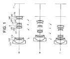
- Fig. 1 is a diagram showing a lens configuration of a zoom lens system according to Example 1.
- the zoom lens system according to Example 1 is composed of, in order from an object, a first lens group G1 having negative refractive power, a second lens group G2 having positive refractive power, a third lens group G3 having negative refractive power, and a fourth lens group G4 having positive refractive power.
- the first lens group G1 is composed of, in order from the object, a negative meniscus lens L11 having a convex surface facing the object, a double concave negative lens L12, and a positive meniscus lens L13 having a convex surface facing the object.
- the second lens group G2 is composed of, in order from the object, a cemented positive lens constructed by a negative meniscus lens L21 having a convex surface facing the object cemented with a double convex positive lens L22, and a positive meniscus lens L23 having a convex surface facing the object.
- the third lens group G3 is composed of a cemented negative lens constructed by, in order from the object, a positive meniscus lens L31 having a convex surface facing the image cemented with a double concave negative lens L32.
- the fourth lens group G4 is composed of, in order from the object, a positive meniscus lens L41 having a convex surface facing the image, and a cemented positive lens constructed by a double convex positive lens L42 cemented with a negative meniscus lens L43 having a convex surface facing the image.
- an aperture stop S is disposed to the object side of the third lens group G3 adjacent thereto, and moved with the third lens group G3 in a body upon zooming from the wide-angle end state to the telephoto end state.
- a flare stopper FS is disposed to the image side of the fourth lens group G4 adjacent thereto.
- f denotes a focal length
- FNO denotes an f-number
- 2 ⁇ denotes an angle of view
- the left most column shows the lens surface number counted in order from the object side
- the second column shows a radius of curvature "r”
- the third column shows a distance "d" along the optical axis between the lens surfaces
- the position of an aspherical surface is expressed by attaching "*" to the right side of the surface number in [Lens Data] and paraxial radius of curvature is shown in the second column.
- Bf denotes a back focal length.
- W, M, and T denote a wide-angle end state, an intermediate focal length state, and a telephoto end state, respectively.
- mm is generally used for the unit of length such as the focal length, the radius of curvature, and the distance to the next lens surface.
- the unit is not necessary to be limited to "mm", and any other suitable unit can be used.
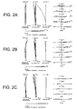
- Figs. 2A, 2B, and 2C are graphs showing various aberrations of the zoom lens system according to Example 1 in which Fig. 2A shows various aberrations in a wide-angle end state, Fig. 2B shows various aberrations in an intermediate focal length state, and Fig. 2C shows various aberrations in a telephoto end state.
- FNO denotes an f-number
- A denotes an incident angle of the principal ray, in other words a half angle of view (unit: degree).
- FNO denotes the f-number with respect to the maximum aperture.
- a solid line indicates a sagittal image plane
- a broken line indicates a meridional image plane
- the zoom lens system according to Example 1 shows superb optical performance as a result of good corrections to various aberrations in the wide-angle end state, in the intermediate focal length state, and in the telephoto end state.
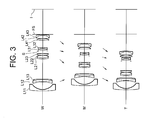
- Fig. 3 is a diagram showing a lens configuration of a zoom lens system according to Example 2.
- the zoom lens system according to Example 2 is composed of, in order from an object, a first lens group G1 having negative refractive power, a second lens group G2 having positive refractive power, a third lens group G3 having negative refractive power, and a fourth lens group G4 having positive refractive power.
- the first lens group G1 is composed of, in order from the object, a negative meniscus lens L11 having a convex surface facing the object, and a cemented negative lens constructed by a double concave negative lens L12 cemented with a double convex positive lens L13.
- the second lens group G2 is composed of, in order from the object, a cemented positive lens constructed by a negative meniscus lens L21 having a convex surface facing the object cemented with a double convex positive lens L22, and a positive meniscus lens having a convex surface facing the object.
- the third lens group G3 is composed of a cemented negative lens constructed by, in order from the object, a positive meniscus lens L31 having a convex surface facing the image cemented with a double concave negative lens L32.
- the fourth lens group G4 is composed of, in order from the object, a positive meniscus lens L41 having a convex surface facing the image, and a cemented positive lens constructed by a double convex positive lens L42 cemented with a negative meniscus lens L43 having a convex surface facing the image.
- an aperture stop S is disposed to the object side of the third lens group G3 adjacent thereto, and moved with the third lens group G3 in a body upon zooming from the wide-angle end state to the telephoto end state.
- a flare stopper FS is disposed to the image side of the fourth lens group G4 adjacent thereto.
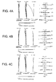
- Figs. 4A, 4B, and 4C are graphs showing various aberrations of the zoom lens system according to Example 2 in which Fig. 4A shows various aberrations in a wide-angle end state, Fig. 4B shows various aberrations in an intermediate focal length state, and Fig. 4C shows various aberrations in a telephoto end state.
- the zoom lens system according to Example 2 shows superb optical performance as a result of good corrections to various aberrations in the wide-angle end state, in the intermediate focal length state, and in the telephoto end state.
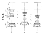
- Fig. 5 is a diagram showing a lens configuration of a zoom lens system according to Example 3.
- the zoom lens system according to Example 3 is composed of, in order from an object, a first lens group G1 having negative refractive power, a second lens group G2 having positive refractive power, a third lens group G3 having negative refractive power, and a fourth lens group G4 having positive refractive power.
- the first lens group G1 is composed of, in order from the object, a negative meniscus lens L11 having a convex surface facing the object, and a cemented negative lens constructed by a double concave negative lens L12 cemented with a positive meniscus lens L13 having a convex surface facing the object.
- the second lens group G2 is composed of, in order from the object, a double convex positive lens L21, and a cemented positive lens constructed by a double convex positive lens L22 cemented with a double concave negative lens L23.
- the third lens group G3 is composed of a cemented negative lens constructed by, in order from the object, a positive meniscus lens L31 having a convex surface facing the image cemented with a double concave negative lens L32.
- the fourth lens group G4 is composed of, in order from the object, a positive meniscus lens L41 having a convex surface facing the image, and a cemented positive lens constructed by a double convex positive lens L42 cemented with a negative meniscus lens L43 having a convex surface facing the image.
- an aperture stop S is disposed to the object side of the third lens group G3 adjacent thereto, and moved with the third lens group G3 in a body upon zooming from the wide-angle end state to the telephoto end state.
- a flare stopper FS is disposed to the image side of the fourth lens group G4 adjacent thereto.
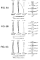
- Figs. 6A, 6B, and 6C are graphs showing various aberrations of the zoom lens system according to Example 3 in which Fig. 6A shows various aberrations in a wide-angle end state, Fig. 6B shows various aberrations in an intermediate focal length state, and Fig. 6C shows various aberrations in a telephoto end state.
- the zoom lens system according to Example 3 shows superb optical performance as a result of good corrections to various aberrations in the wide-angle end state, in the intermediate focal length state, and in the telephoto end state.
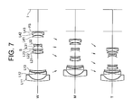
- Fiq. 7 is a diagram showing a lens configuration of a zoom lens system according to Example 4.
- the zoom lens system according to Example 4 is composed of, in order from an object, a first lens group G1 having negative refractive power, a second lens group G2 having positive refractive power, a third lens group G3 having negative refractive power, and a fourth lens group G4 having positive refractive power.
- the first lens group G1 is composed of, in order from the object, a negative meniscus lens L11 having a convex surface facing the object, a double concave negative lens L12, and a positive meniscus lens L13 having a convex surface facing the object.
- the second lens group G2 is composed of, in order from the object, a cemented positive lens constructed by a negative meniscus lens L21 having a convex surface facing the object cemented with a double convex positive lens L22, and a positive meniscus lens L23 having a convex surface facing the object.
- the third lens group G3 is composed of a cemented negative lens constructed by, in order from the object, a positive meniscus lens L31 having a convex surface facing the image cemented with a double concave negative lens L32.
- the fourth lens group G4 is composed of, in order from the object, a positive meniscus lens L41 having a convex surface facing the image, and a cemented positive lens constructed by a double convex positive lens L42 cemented with a negative meniscus lens L43 having a convex surface facing the image.
- an aperture stop S is disposed to the object side of the third lens group G3 adjacent thereto, and moved with the third lens group G3 in a body upon zooming from the wide-angle end state to the telephoto end state.
- a flare stopper FS is disposed to the image side of the fourth lens group G4 adjacent thereto.
- Figs. 8A, 8B, and 8C are graphs showing various aberrations of the zoom lens system according to Example 4 in which Fig. 8A shows various aberrations in a wide-angle end state, Fig. 8B shows various aberrations in an intermediate focal length state, and Fig. 8C shows various aberrations in a telephoto end state.
- the zoom lens system according to Example 4 shows superb optical performance as a result of good corrections to various aberrations in the wide-angle end state, in the intermediate focal length state, and in the telephoto end state.
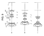
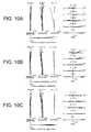
- Fig. 9 is a diagram showing a lens configuration of a zoom lens system according to Example 5.
- the zoom lens system according to Example 5 is composed of, in order from an object, a first lens group G1 having negative refractive power, a second lens group G2 having positive refractive power, a third lens group G3 having negative refractive power, and a fourth lens group G4 having positive refractive power.
- the first lens group G1 is composed of, in order from the object, a negative meniscus lens L11 having a convex surface facing the object, a double concave negative lens L12, and a positive meniscus lens L13 having a convex surface facing the object.
- the second lens group G2 is composed of, in order from the object, a double convex positive lens L21, and a cemented positive lens constructed by a double convex positive lens L22 cemented with a negative meniscus lens L23 having a convex surface facing the image.
- the third lens group G3 is composed of a cemented negative lens constructed by, in order from the object, a positive meniscus lens L31 having a convex surface facing the image cemented with a double concave negative lens L32.
- the fourth lens group G4 is composed of a cemented positive lens constructed by, in order from the object, a double convex positive lens L41 cemented with a negative meniscus lens L42 having a convex surface facing the image.
- an aperture stop S is disposed to the object side of the third lens group G3 adjacent thereto, and moved with the third lens group G3 in a body upon zooming from the wide-angle end state to the telephoto end state.
- a flare stopper FS is disposed to the image side of the fourth lens group G4 adjacent thereto.
- Figs. 10A, 10B, and 10C are graphs showing various aberrations of the zoom lens system according to Example 5 in which Fig. 10A shows various aberrations in a wide-angle end state, Fig. 10B shows various aberrations in an intermediate focal length state, and Fig. 10C shows various aberrations in a telephoto end state.
- the zoom lens system according to Example 5 shows superb optical performance as a result of good corrections to various aberrations in the wide-angle end state, in the intermediate focal length state, and in the telephoto end state.
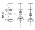
- Fig. 11 is a diagram showing a lens configuration of a zoom lens system according to Example 6.
- the zoom lens system according to Example 6 is composed of, in order from an object, a first lens group G1 having negative refractive power, a second lens group G2 having positive refractive power, a third lens group G3 having negative refractive power, and a fourth lens group G4 having positive refractive power.
- the first lens group G1 is composed of, in order from the object, a negative meniscus lens L11 having a convex surface facing the object, a negative meniscus lens L12 having a convex surface facing the object, and a positive meniscus lens L13 having a convex surface facing the object.
- the second lens group G2 is composed of a cemented positive lens constructed by, in order from the object, a double convex positive lens L21 cemented with a negative meniscus lens L22 having a convex surface facing the image.
- the third lens group G3 is composed of a cemented negative lens constructed by, in order from the object, a positive meniscus lens L31 having a convex surface facing the image cemented with a double concave negative lens L32.
- the fourth lens group G4 is composed of, in order from the object, a positive meniscus lens L41 having a convex surface facing the image, and a cemented positive lens constructed by a double convex positive lens L42 cemented with a negative meniscus lens L43 having a convex surface facing the image.
- an aperture stop S is disposed to the object side of the third lens group G3 adjacent thereto, and moved with the third lens group G3 in a body upon zooming from the wide-angle end state to the telephoto end state.
- a flare stopper FS is disposed to the image side of the fourth lens group G4 adjacent thereto.
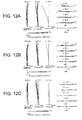
- Figs. 12A, 12B, and 12C are graphs showing various aberrations of the zoom lens system according to Example 6 in which Fig. 12A shows various aberrations in a wide-angle end state, Fig. 12B shows various aberrations in an intermediate focal length state, and Fig. 12C shows various aberrations in a telephoto end state.
- the zoom lens system according to Example 6 shows superb optical performance as a result of good corrections to various aberrations in the wide-angle end state, in the intermediate focal length state, and in the telephoto end state.
- each example makes it possible to provide a zoom lens system that is inexpensive, compact and lightweight with high optical performance.
- the lens-group configuration according to the present application is not limited to this, and is applicable to other lens-group configurations such as a five-lens-group configuration.
- a portion of a lens group, a single lens group, or a plurality of lens groups may be moved along the optical axis.
- the focusing lens group(s) may be used for auto focus, and suitable for being driven by a motor such as an ultrasonic motor.
- a portion of a lens group, or a single lens group may be moved as a vibration reduction lens group in a direction perpendicular to the optical axis.
- Any lens surface composing the zoom lens system according to the present application may be an aspherical surface.
- the aspherical surface may be fabricated by a fine grinding process, a glass molding process that a glass material is formed into an aspherical shape by a mold, or a compound type process that a resin material is formed into an aspherical shape on a glass surface.
- an antireflection coating having high transmittance over a broad wavelength range may be applied to each lens surface to reduce flare or ghost images, so that high optical performance with high contrast can be attained.
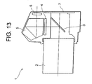
- Fig. 13 is a schematic diagram showing a configuration of a camera using the zoom lens system according to Examples 1.
- the camera 1 is a single-lens reflex digital camera equipped with the zoom lens system according to Example 1 as an image-taking lens 2.
- the camera 1 In the camera 1, light emitted from a subject (not shown) is converged by an image-taking lens 2, and focused on a focusing screen 4 through a quick return mirror 3. The subject image focused on the focusing screen 4 is reflected a plurality of times by a pentagonal roof prism 5, and led to an eyepiece 6. Therefore, a photographer can observe the subject image as an erected image through the eyepiece 6.
- the quick return mirror 3 is removed from an optical path, and the light from the subject (not shown) reaches an imaging device 7.
- the light from the subject is captured by the imaging device 7 and stored in a memory (not shown) as a subject image. In this manner, the photographer can take a picture of the subject by the camera 1.
- the zoom lens system according to Example 1 of the first embodiment attached to the camera 1 as an image-taking lens 2 makes it possible to realize to be inexpensive, compact and lightweight with high optical performance. Accordingly, the camera 1 makes it possible to realize to be inexpensive, compact and lightweight with high optical performance.
- the present application is not limited to this, and it is needless to say that the similar effect can be obtained by a camera equipped with the zoom lens system according to any one of Examples 2 through 6 of the present application.
- the present application makes it possible to realize a zoom lens system being inexpensive, compact and lightweight with high optical performance, an imaging apparatus, and a method for varying a focal length the zoom lens system.
Applications Claiming Priority (2)
| Application Number | Priority Date | Filing Date | Title |
|---|---|---|---|
| JP2006173010 | 2006-06-22 | ||
| JP2007154234A JP5056184B2 (ja) | 2006-06-22 | 2007-06-11 | ズームレンズ、撮像装置、ズームレンズの変倍方法 |
Publications (1)
| Publication Number | Publication Date |
|---|---|
| EP1870760A1 true EP1870760A1 (fr) | 2007-12-26 |
Family
ID=38457692
Family Applications (1)
| Application Number | Title | Priority Date | Filing Date |
|---|---|---|---|
| EP07252497A Withdrawn EP1870760A1 (fr) | 2006-06-22 | 2007-06-20 | Zoom de type rétrofocus à quatre groupes de lentilles |
Country Status (4)
| Country | Link |
|---|---|
| US (1) | US7599123B2 (fr) |
| EP (1) | EP1870760A1 (fr) |
| JP (1) | JP5056184B2 (fr) |
| CN (1) | CN101093278B (fr) |
Families Citing this family (17)
| Publication number | Priority date | Publication date | Assignee | Title |
|---|---|---|---|---|
| JP2008191385A (ja) * | 2007-02-05 | 2008-08-21 | Sony Corp | ズームレンズ及び撮像装置 |
| JP5078498B2 (ja) * | 2007-08-09 | 2012-11-21 | キヤノン株式会社 | ズームレンズ及びそれを有する撮像装置 |
| JP5197242B2 (ja) * | 2008-09-01 | 2013-05-15 | キヤノン株式会社 | ズームレンズ及びそれを有する撮像装置 |
| US8503102B2 (en) | 2011-04-19 | 2013-08-06 | Panavision International, L.P. | Wide angle zoom lens |
| JP2014048376A (ja) * | 2012-08-30 | 2014-03-17 | Nikon Corp | 変倍光学系、この変倍光学系を有する光学装置、及び、変倍光学系の製造方法 |
| JP6260075B2 (ja) * | 2012-08-30 | 2018-01-17 | 株式会社ニコン | 変倍光学系、及び、この変倍光学系を有する光学装置 |
| JP6256732B2 (ja) * | 2012-08-30 | 2018-01-10 | 株式会社ニコン | 変倍光学系、及び、この変倍光学系を有する光学装置 |
| JP6098863B2 (ja) * | 2012-08-30 | 2017-03-22 | 株式会社ニコン | 変倍光学系、この変倍光学系を有する光学装置、及び、変倍光学系の製造方法 |
| CN103176263B (zh) * | 2013-02-20 | 2015-10-28 | 福建福光股份有限公司 | 三百万像素日夜两用P-iris镜头 |
| CN103389563B (zh) * | 2013-08-15 | 2015-06-17 | 福建福光数码科技有限公司 | Cs接口塑料结构超清摄像镜头 |
| JP6197489B2 (ja) * | 2013-08-29 | 2017-09-20 | 株式会社ニコン | 変倍光学系、光学装置、変倍光学系の製造方法 |
| JP2015121768A (ja) | 2013-11-21 | 2015-07-02 | 株式会社ニコン | ズームレンズ、光学機器及びズームレンズの製造方法 |
| JP6602027B2 (ja) | 2015-03-13 | 2019-11-06 | キヤノン株式会社 | ズームレンズ及びそれを有する撮像装置 |
| CN105301770B (zh) * | 2015-12-01 | 2018-02-06 | 中国航空工业集团公司洛阳电光设备研究所 | 一种可见光三视场光学成像系统 |
| KR102600453B1 (ko) * | 2016-02-19 | 2023-11-10 | 삼성전자주식회사 | 옵티칼 렌즈 어셈블리 및 이를 포함한 전자 장치 |
| CN109804292B (zh) * | 2016-10-07 | 2021-05-25 | 株式会社尼康 | 变倍光学系统以及光学设备 |
| JP7183032B2 (ja) * | 2018-12-25 | 2022-12-05 | 株式会社タムロン | ズームレンズ及び撮像装置 |
Citations (2)
| Publication number | Priority date | Publication date | Assignee | Title |
|---|---|---|---|---|
| JPH0519170A (ja) * | 1991-02-15 | 1993-01-29 | Asahi Optical Co Ltd | ズームレンズ |
| JPH11174328A (ja) * | 1997-12-15 | 1999-07-02 | Canon Inc | ズームレンズ |
Family Cites Families (17)
| Publication number | Priority date | Publication date | Assignee | Title |
|---|---|---|---|---|
| JPH0451006A (ja) | 1990-06-18 | 1992-02-19 | Olympus Optical Co Ltd | ズームレンズ |
| JPH04163415A (ja) * | 1990-10-26 | 1992-06-09 | Canon Inc | 広角ズームレンズ |
| GB2253281B (en) * | 1991-02-15 | 1994-05-25 | Asahi Optical Co Ltd | Zoom lens |
| US5576890A (en) | 1992-02-28 | 1996-11-19 | Canon Kabushiki Kaisha | Zoom lens |
| US5585970A (en) | 1994-04-19 | 1996-12-17 | Nikon Corporation | Zoom lens with high zoom ratio |
| JPH1020194A (ja) * | 1996-07-08 | 1998-01-23 | Konica Corp | ズームレンズ |
| JP4392901B2 (ja) * | 1999-05-26 | 2010-01-06 | キヤノン株式会社 | ズームレンズ |
| JP2001042217A (ja) * | 1999-07-30 | 2001-02-16 | Canon Inc | ズームレンズ |
| JP2001116992A (ja) | 1999-10-18 | 2001-04-27 | Canon Inc | ズームレンズ |
| JP3752174B2 (ja) * | 2001-10-29 | 2006-03-08 | ペンタックス株式会社 | ズームレンズ系 |
| JP4366091B2 (ja) * | 2003-02-04 | 2009-11-18 | キヤノン株式会社 | ズームレンズ |
| US7106520B2 (en) | 2003-05-06 | 2006-09-12 | Pentax Corporation | Wide-angle zoom lens system |
| JP4324508B2 (ja) * | 2003-05-06 | 2009-09-02 | Hoya株式会社 | 広角ズームレンズ系 |
| JP4289958B2 (ja) | 2003-09-19 | 2009-07-01 | キヤノン株式会社 | ズームレンズ及びそれを有する撮像装置 |
| JP4642386B2 (ja) * | 2004-06-09 | 2011-03-02 | キヤノン株式会社 | ズームレンズ及びそれを有する撮像装置 |
| JP4834360B2 (ja) * | 2005-09-12 | 2011-12-14 | キヤノン株式会社 | ズームレンズ及びそれを有する撮像装置 |
| US7333273B2 (en) * | 2006-03-24 | 2008-02-19 | Nikon Corporation | Zoom lens system, imaging apparatus and method for varying focal length |
-
2007
- 2007-06-11 JP JP2007154234A patent/JP5056184B2/ja not_active Expired - Fee Related
- 2007-06-20 US US11/765,816 patent/US7599123B2/en not_active Expired - Fee Related
- 2007-06-20 EP EP07252497A patent/EP1870760A1/fr not_active Withdrawn
- 2007-06-22 CN CN2007101100971A patent/CN101093278B/zh not_active Expired - Fee Related
Patent Citations (2)
| Publication number | Priority date | Publication date | Assignee | Title |
|---|---|---|---|---|
| JPH0519170A (ja) * | 1991-02-15 | 1993-01-29 | Asahi Optical Co Ltd | ズームレンズ |
| JPH11174328A (ja) * | 1997-12-15 | 1999-07-02 | Canon Inc | ズームレンズ |
Non-Patent Citations (1)
| Title |
|---|
| SCHOTT AG: "Übersichtsplan für die optischen Glasarten", 1996, SCHOTT AG, GERMANY, XP002450003 * |
Also Published As
| Publication number | Publication date |
|---|---|
| JP2008026880A (ja) | 2008-02-07 |
| US7599123B2 (en) | 2009-10-06 |
| US20080002263A1 (en) | 2008-01-03 |
| CN101093278A (zh) | 2007-12-26 |
| CN101093278B (zh) | 2012-07-04 |
| JP5056184B2 (ja) | 2012-10-24 |
Similar Documents
| Publication | Publication Date | Title |
|---|---|---|
| EP2620796B1 (fr) | Système optique et appareil d'imagerie | |
| US7599123B2 (en) | Zoom lens system, imaging apparatus and method for varying focal length | |
| US7961409B2 (en) | Zoom lens system, optical apparatus, and method for zooming | |
| US10437026B2 (en) | Zoom lens system, imaging apparatus, and method for zooming the zoom lens system | |
| US7551367B2 (en) | Wide-angle lens, optical apparatus and method for focusing | |
| EP2360504B1 (fr) | Système de lentilles de zoom, appareil optique et procédé de fabrication de lentilles de zoom | |
| EP2071379B1 (fr) | Objectif macro du type téléobjectif ayant trois groupes de lentilles et focalisation avant, et son procédé de fabrication | |
| US8144403B2 (en) | Zoom lens system, optical apparatus, and method for zooming | |
| US7924511B2 (en) | Optical system, method for focusing, and imaging apparatus equipped therewith | |
| US7492524B2 (en) | Zoom lens system, imaging apparatus, method for vibration reduction, and method for varying focal length | |
| US7333273B2 (en) | Zoom lens system, imaging apparatus and method for varying focal length | |
| EP1998204B1 (fr) | Zoom téléphoto anti-vibrations avec quatre groupes de lentilles et à focalisation avec le groupe de lentilles arrière | |
| US7492526B2 (en) | High zoom ratio zoom lens, optical apparatus using the same, and method for varying focal length | |
| US11668899B2 (en) | Zoom lens, optical apparatus, and method for manufacturing zoom lens | |
| US7920341B2 (en) | Optical system, imaging apparatus, and method for forming image by the optical system |
Legal Events
| Date | Code | Title | Description |
|---|---|---|---|
| PUAI | Public reference made under article 153(3) epc to a published international application that has entered the european phase |
Free format text: ORIGINAL CODE: 0009012 |
|
| AK | Designated contracting states |
Kind code of ref document: A1 Designated state(s): AT BE BG CH CY CZ DE DK EE ES FI FR GB GR HU IE IS IT LI LT LU LV MC MT NL PL PT RO SE SI SK TR |
|
| AX | Request for extension of the european patent |
Extension state: AL BA HR MK YU |
|
| AKX | Designation fees paid | ||
| REG | Reference to a national code |
Ref country code: DE Ref legal event code: 8566 |
|
| STAA | Information on the status of an ep patent application or granted ep patent |
Free format text: STATUS: THE APPLICATION IS DEEMED TO BE WITHDRAWN |
|
| 18D | Application deemed to be withdrawn |
Effective date: 20080627 |