EP1306336B1 - Dynamische Abstandskorrektur für ein Kuvertierunterystem - Google Patents
Dynamische Abstandskorrektur für ein Kuvertierunterystem Download PDFInfo
- Publication number
- EP1306336B1 EP1306336B1 EP02023785A EP02023785A EP1306336B1 EP 1306336 B1 EP1306336 B1 EP 1306336B1 EP 02023785 A EP02023785 A EP 02023785A EP 02023785 A EP02023785 A EP 02023785A EP 1306336 B1 EP1306336 B1 EP 1306336B1
- Authority
- EP
- European Patent Office
- Prior art keywords
- transport
- pitch
- upstream
- correcting
- document
- Prior art date
- Legal status (The legal status is an assumption and is not a legal conclusion. Google has not performed a legal analysis and makes no representation as to the accuracy of the status listed.)
- Expired - Lifetime
Links
- 238000012937 correction Methods 0.000 title claims description 44
- 238000011144 upstream manufacturing Methods 0.000 claims description 87
- 230000001133 acceleration Effects 0.000 claims description 39
- 238000000034 method Methods 0.000 claims description 22
- 238000006073 displacement reaction Methods 0.000 claims description 17
- 101150090128 PCM1 gene Proteins 0.000 description 58
- 230000032258 transport Effects 0.000 description 46
- 238000012545 processing Methods 0.000 description 13
- 230000007723 transport mechanism Effects 0.000 description 11
- 238000004364 calculation method Methods 0.000 description 10
- 230000003247 decreasing effect Effects 0.000 description 6
- 238000012546 transfer Methods 0.000 description 6
- 230000003466 anti-cipated effect Effects 0.000 description 5
- 230000008569 process Effects 0.000 description 5
- 230000001276 controlling effect Effects 0.000 description 4
- 238000001514 detection method Methods 0.000 description 3
- 230000000694 effects Effects 0.000 description 3
- 230000008859 change Effects 0.000 description 2
- 238000010438 heat treatment Methods 0.000 description 2
- 238000003780 insertion Methods 0.000 description 2
- 230000037431 insertion Effects 0.000 description 2
- 230000007246 mechanism Effects 0.000 description 2
- 230000000979 retarding effect Effects 0.000 description 2
- 238000007789 sealing Methods 0.000 description 2
- 230000009471 action Effects 0.000 description 1
- 238000004458 analytical method Methods 0.000 description 1
- 230000008901 benefit Effects 0.000 description 1
- 230000003116 impacting effect Effects 0.000 description 1
- 238000009434 installation Methods 0.000 description 1
- 230000010354 integration Effects 0.000 description 1
- 238000004519 manufacturing process Methods 0.000 description 1
- 239000002994 raw material Substances 0.000 description 1
- 230000001105 regulatory effect Effects 0.000 description 1
- 230000035945 sensitivity Effects 0.000 description 1
- 238000000926 separation method Methods 0.000 description 1
- 238000005303 weighing Methods 0.000 description 1
Images


Classifications
-
- B—PERFORMING OPERATIONS; TRANSPORTING
- B65—CONVEYING; PACKING; STORING; HANDLING THIN OR FILAMENTARY MATERIAL
- B65H—HANDLING THIN OR FILAMENTARY MATERIAL, e.g. SHEETS, WEBS, CABLES
- B65H43/00—Use of control, checking, or safety devices, e.g. automatic devices comprising an element for sensing a variable
-
- B—PERFORMING OPERATIONS; TRANSPORTING
- B65—CONVEYING; PACKING; STORING; HANDLING THIN OR FILAMENTARY MATERIAL
- B65H—HANDLING THIN OR FILAMENTARY MATERIAL, e.g. SHEETS, WEBS, CABLES
- B65H29/00—Delivering or advancing articles from machines; Advancing articles to or into piles
- B65H29/12—Delivering or advancing articles from machines; Advancing articles to or into piles by means of the nip between two, or between two sets of, moving tapes or bands or rollers
-
- B—PERFORMING OPERATIONS; TRANSPORTING
- B65—CONVEYING; PACKING; STORING; HANDLING THIN OR FILAMENTARY MATERIAL
- B65H—HANDLING THIN OR FILAMENTARY MATERIAL, e.g. SHEETS, WEBS, CABLES
- B65H2220/00—Function indicators
- B65H2220/09—Function indicators indicating that several of an entity are present
-
- B—PERFORMING OPERATIONS; TRANSPORTING
- B65—CONVEYING; PACKING; STORING; HANDLING THIN OR FILAMENTARY MATERIAL
- B65H—HANDLING THIN OR FILAMENTARY MATERIAL, e.g. SHEETS, WEBS, CABLES
- B65H2301/00—Handling processes for sheets or webs
- B65H2301/40—Type of handling process
- B65H2301/44—Moving, forwarding, guiding material
- B65H2301/445—Moving, forwarding, guiding material stream of articles separated from each other
- B65H2301/4452—Regulating space between separated articles
-
- B—PERFORMING OPERATIONS; TRANSPORTING
- B65—CONVEYING; PACKING; STORING; HANDLING THIN OR FILAMENTARY MATERIAL
- B65H—HANDLING THIN OR FILAMENTARY MATERIAL, e.g. SHEETS, WEBS, CABLES
- B65H2404/00—Parts for transporting or guiding the handled material
- B65H2404/10—Rollers
- B65H2404/14—Roller pairs
-
- B—PERFORMING OPERATIONS; TRANSPORTING
- B65—CONVEYING; PACKING; STORING; HANDLING THIN OR FILAMENTARY MATERIAL
- B65H—HANDLING THIN OR FILAMENTARY MATERIAL, e.g. SHEETS, WEBS, CABLES
- B65H2511/00—Dimensions; Position; Numbers; Identification; Occurrences
- B65H2511/20—Location in space
- B65H2511/22—Distance
-
- B—PERFORMING OPERATIONS; TRANSPORTING
- B65—CONVEYING; PACKING; STORING; HANDLING THIN OR FILAMENTARY MATERIAL
- B65H—HANDLING THIN OR FILAMENTARY MATERIAL, e.g. SHEETS, WEBS, CABLES
- B65H2513/00—Dynamic entities; Timing aspects
- B65H2513/20—Acceleration or deceleration
-
- B—PERFORMING OPERATIONS; TRANSPORTING
- B65—CONVEYING; PACKING; STORING; HANDLING THIN OR FILAMENTARY MATERIAL
- B65H—HANDLING THIN OR FILAMENTARY MATERIAL, e.g. SHEETS, WEBS, CABLES
- B65H2701/00—Handled material; Storage means
- B65H2701/10—Handled articles or webs
- B65H2701/19—Specific article or web
- B65H2701/1916—Envelopes and articles of mail
Definitions
- the present invention relates to a system and method for correcting pitch between documents traveling in a high speed mass mail processing and inserting system.
- pitch refers to the spacing between documents traveling in an inserter system. Properly controlled and predictable document pitch is necessary for reliable operation of high speed mass mail processing and inserter systems of this sort.
- Inserter systems such as those applicable for use with the present invention, are typically used by organizations such as banks, insurance companies and utility companies for producing a large volume of specific mailings where the contents of each mail item are directed to a particular addressee. Additional, other organizations, such as direct mailers, use inserts for producing a large volume of generic mailings where the contents of each mail item are substantially identical for each addressee. Examples of such inserter systems are the 8 Series and 9 Series inserter systems available from Pitney Bowes Inc. of Stamford, Connecticut, USA.
- the typical inserter system resembles a manufacturing assembly line. Sheets and other raw materials (other sheets, enclosures, and envelopes) enter the inserter system as inputs. Then, a plurality of different modules or workstations in the inserter system work cooperatively to process the sheets until a finished mail piece is produced. The exact configuration of each inserter system depends upon the needs of each particular customer or installation.
- inserter systems prepare mail pieces by gathering collations of documents on a conveyor. The collations are then transported on the conveyor to an insertion station where they are automatically stuffed into envelopes. After being stuffed with the collations, the envelopes are removed from the insertion station for further processing. Such further processing may include automated closing and sealing the envelope flap, weighing the envelope, applying postage to the envelope, and finally sorting and stacking the envelopes.
- An inserter system may typically include a right angle transfer module to perform a 90-degree change of direction of documents flowing through the inserter system.
- the right angle transfer module allows for different configurations of modules in an inserter system and provides flexibility in designing a system footprint to fit a floor plan.
- Such a right angle transfer module is typically located after the envelope-stuffing module, and before the final output modules.
- Right angle transfer modules are well known in the art, and may take many different forms.
- envelopes will preferably remain a regulated distance (or "pitch") from each other as they are transported through the system.
- envelopes typically lie horizontally, with their edges perpendicular and parallel to the transport path, and have a uniform position relative to the sides of the transport path during processing.
- Predictable envelope positioning helps the processing modules perform their respective functions. For example, if an envelope enters a postage-printing module crooked, it is less likely that a proper postage mark will be printed. For these reasons it is important to ensure that envelopes do not lie askew on the transport path, or at varying distances from the sides of the transport path.
- envelopes or other documents
- This aligning function may be incorporated into a right angle transfer module, whereby a document may impact against an aligning wall as part of performing a 90-degree change of direction.
- the envelope edge that is urged against the aligning wall is the bottom edge, opposite from the top flapped edge of the envelope.
- the action of impacting the bottom edge of the envelope against the aligning wall may also serve the purpose of settling the stuffed collation of documents towards the bottom of the envelope. By settling the collation to the bottom of the envelope it is more likely that no documents will protrude above the top edge of the envelope, and that the envelope flap can be closed and sealed successfully.
- a subsequent envelope may arrive at the postage metering device before the meter has had time to reset, or perhaps even before the previous envelope has left.
- the meter will not be able to perform its function on the subsequent envelope before a subsequent envelope arrives, and the whole system may be forced to a halt.
- DE-C-196 42 350 describes a pitch adjusting mechanism for a stream of mailpieces in which the pitch spacing between consecutive items is measured and adjustments made by varying the length of the transport path.
- Jam detection within the aligning module may become difficult to manage as a result of excess pitch variation. Jam detection is based on theoretical envelope arrival and departure times detected by tracking sensors along the envelope path. Variability in the aligner module will force the introduction of wide margins of error in the tracking algorithm, particularly for start and stop transport conditions, making jam detection less reliable for that module.
- Pitch variation occurs for a number of reasons.
- One source of variation can be an aligner module for a high-speed inserter system, as described above.
- the impact causes the envelopes to decelerate in a manner that may cause the gap between envelopes to vary as much as +/- 30 ms. While such a variation might not be significant in slower machines, this variation can be too much for the close tolerances in current high speed inserter machines.
- variation may be the result of "dither" in the transport of stuffed envelopes.
- Different envelopes may be stuffed with different quantities of sheets that form the individual mail pieces.
- envelopes will vary in weight.
- Such variation in weight will cause envelopes to have different acceleration, momentum and frictional forces acting upon them as they are transported in the inserter output subsystem.
- different envelopes will experience different slippage as transport mechanisms such as rollers and belts are used to transport them. Accordingly, such dither may result in an additional +/- 30 ms variation in the spacing between envelopes.
- the present application describes a system and a method to reduce variation in envelope pitch to further meet the needs and shortcomings of the conventional art described above.
- a pitch correcting system for correcting spacing between serially fed documents in an inserter system, the pitch correcting system comprising: an upstream transport for transporting documents at a nominal velocity in a transport path; a downstream transport for transporting documents at the nominal velocity in the transport path; a pitch correcting transport located in between the upstream transport and the downstream transport, the pitch correcting transport for receiving documents from the upstream transport and transporting them to the downstream transport; a sensor arrangement for generating pitch signals identifying a measured pitch between a downstream document and a consecutive upstream document arriving at the pitch correcting transport; and a controller for receiving the pitch signals from the sensor arrangement, the controller comparing the measured pitch with a nominal pitch and determining a variance of the measured pitch from the nominal pitch, the controller controlling an acceleration of the pitch correcting transport to correct the variance while the upstream document is under the control of the pitch correcting transport, and the controller controlling the pitch correcting transport to return the upstream document to the nominal velocity before transferring the upstream document to the downstream transport
- a method for correcting pitch between serially fed documents in an inserter system comprising: transporting documents at a nominal velocity with an upstream transport; transporting documents at the nominal velocity with a downstream transport; transporting documents at variable velocities from the upstream transport to the downstream transport via a pitch correcting transport; sensing a measured pitch between a downstream document and a consecutive upstream document arriving at the pitch correcting transport; comparing the measured pitch to a nominal pitch to determine a pitch variance; characterized by: controlling the variable velocities of the pitch correcting transport while the upstream document is under the control of the pitch correcting transport to correct the pitch variance; and controlling the variable velocities of the pitch correcting transport to return the upstream document to the nominal velocity before transferring the upstream document to the downstream transport.
- the present system addresses the problems of the conventional art by providing a pitch correcting module ("PCM").
- the pitch correcting module is positioned upstream of modules that are sensitive to variation in pitch, in order that such variations may be corrected before the envelopes reach those modules.
- the pitch correction module includes a transport mechanism, such as hard nip rollers, or conveyor belts, to speed up or slow down the transport of envelopes in order to correct pitch variations.
- the relative spacing of envelopes is preferably detected by sensors which sense envelopes entering and leaving the pitch correcting module. Based on input from the sensors, a processing device controls the transport mechanism of the PCM to speed up or slow down the envelope in accordance with a predetermined algorithm.
- the pitch correcting module is dimensioned to accommodate the varying envelopes sizes that the inserter system is designed to process, while at the same time maintaining the capability of the inserter system to operate at its designed speed, and to correct the range of expected unwanted variation.
- the PCM is also designed to provide the necessary accelerations and decelerations to achieve corrections within a range of expected pitch variations.
- the present system includes a pitch correcting module (PCM) 1 positioned between an upstream module 2 and a downstream module 3 .
- PCM pitch correcting module
- An example of upstream module 2 could be a right angle transfer, or an aligner module such as that described in the aforementioned co-pending Application EP-A-1 304 306 corresponding to U.S. patent application number 09/981,959 of Sussmeier.
- An exemplary downstream module 3 could be a diverting module, a metering module, or a stacking module, each of which includes a sensitivity to pitch variation.
- upstream and downstream modules 2 and 3 can be any kinds of modules in an inserter output subsystem.
- PCM 1 , upstream module 2 , and downstream module 3 all include transport mechanisms for moving envelopes along the processing flow path.
- the modules use sets of upper and lower rollers 10 , called nips, between which envelopes are driven in the flow direction.
- rollers 10 are hard-nip rollers to minimize dither.
- the transport mechanism may comprise overlapping sets of conveyor belts between which envelopes are transported.
- rollers 10 for PCM 1 , and modules 2 and 3 are driven by electric motors 11 , 12 , and 13 respectively.
- Motors 11 , 12 , and 13 are preferably independently controllable servo motors.
- Motors 12 and 13 for upstream and downstream modules 2 and 3 drive their respective rollers 10 at a constant velocity, preferably at the desired nominal velocity for envelopes traveling in the system. Accordingly, upstream and downstream modules 2 and 3 will transport envelopes at 85 ips in the flow direction.
- Motor 11 drives rollers 10 in the PCM 1 at varying speeds in order to provide pitch correction capabilities.
- PCM motor 11 is controlled by controller 14 which in turn receives sensor signals including signals from upstream sensor 15 and downstream sensor 16 .
- Sensors 15 and 16 are preferably used to detect the trailing edges of consecutive envelopes passing through the PCM 1 .
- controller 14 can calculate the pitch between consecutive envelopes and adjust the speed of PCM motor 11 to correct variance from a nominal desired pitch.
- the preferred embodiment of the present invention utilizes at least two sensors 15 and 16, one positioned near each of the boundaries between PCM 1 and the upstream and downstream modules 2 and 3 .
- sensors are preferably photo sensors that detect the trail edge of envelopes.
- actual pitch between envelopes is calculated in terms of time and/or displacement. The preferred positioning of the sensors, and the utilization of signals received from the sensors is discussed in more detail below.
- One aspect of the present invention relates to the relative positioning of the transport mechanisms between PCM 1 and the other modules.
- the location of the output of the transport for upstream module 2 is location A.
- the location for the input to the transport of PCM 1 is location B, and the output of the transport mechanism for PCM 1 is location C.
- the input for the transport of downstream module 3 is location D.
- the transport mechanisms are nip rollers 10 for each of the modules. Accordingly locations A, B, C, and D correspond to the respective locations of input and output nip rollers 10 in that embodiment.
- the modules may also include other rollers 10 at other locations, such as the set depicted in FIG. 1 between locations B and C, also driven by motors 11 , 12 , and 13 for the respective modules.
- the three nip rollers sets 10 in PCM 1 will be driven by motor 11 .
- consecutive distances between rollers 10 must be less than the shortest length envelope expected to be conveyed.
- Upstream sensor 15 is preferably located at or near location A, while downstream sensor 16 is preferably located at or near location C.
- pitch correction is calculated after a downstream envelope has received its pitch correction via PCM 1 , and has exited PCM 1 from the nip rollers 10 at location C. In that way, PCM can perform corrections on envelopes one-at-a-time and perform pitch correction operations separately for consecutive envelopes. This arrangement simplifies the calculations to be done by controller 14 in adjusting the speed of PCM 1 to make the appropriate corrections between consecutive envelopes.
- Downstream sensor 16 detects the departure of an envelope from PCM 1 as it exits the rollers 10 at location C. Subsequently, upstream sensor 15 detects the arrival of a new envelope for which control is being transferred from the upstream module 2 to PCM 1 . Controller 14 receives the sensor information and, based on the desired nominal speed and spacing of the envelopes, determines a variation in the measured pitch from the nominal expected pitch.
- Envelopes that arrive later than the desired pitch are accelerated by PCM 1 and then decelerated back to the constant velocity of the downstream module 3 before the lead edge of the envelope reaches location D. This motion has the effect of advancing the envelope closer to the previous downstream envelope.
- PCM 1 The necessary advancing and retarding action of PCM 1 is controlled according to a motion profile calculated by controller 14 .
- Motion profiles are individually calculated for each envelope as a function of the pitch information collected by sensors 15 and 16 .
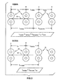
- exemplary motion profiles are illustrated for both an envelope advance profile and an envelope retard profile.
- This figure depicts graphs showing the velocity of the envelope as a function of time while passing through PCM 1 . Acceleration of the envelope is represented by the slope of the lines.
- V transport represents the nominal velocity of the transports in the system, preferably 216 cms -1 (85 ips).
- T correction represents the time during which pitch correction is executed by PCM 1 .
- the area under the velocity curve during T correction represents the displacement of the envelope during pitch correction.
- the area represented by the rectangle below V transport represents the displacement of the envelope (X nominal ) as if it were traveling at nominal speed. However, this displacement must be increased or decreased in order to perform pitch correction. Accordingly, in FIG. 2, X correction represents the area of the increased or decreased displacement above or below the X nominal value resulting from the corresponding acceleration and deceleration.
- the retard profile is illustrated in FIG. 2 using accelerations that are less than that of the advance profile to illustrate a correction that is allowed to occur over a longer pitch correction time, T correction .
- FIG. 2 depicts pitch correction motion profiles having constant acceleration and deceleration values of equal magnitudes, it is not necessary that a motion profile have those characteristics. Rather, the motion profile may take any form, so long as it achieves the required displacement correction within the limited time and space available.
- the preferred embodiment of the present invention does use constant acceleration and deceleration in the manner depicted in FIG. 2. Accordingly, in the preferred embodiment an envelope undergoing pitch correction will undergo acceleration and deceleration of equal magnitudes for half of the envelope travel distance within PCM 1 .
- the calculation for determining accelerations for achieving displacements can be calculated easily by calculating the slope of the lines representing velocity necessary to achieve the desired displacement. If non-linear acceleration is used, the appropriate calculations can be more complicated, but may be achieved using known integration algorithms.
- the pitch correcting profiles as depicted in FIG. 2 are designed to begin when the tail end of the envelope to be pitch corrected exits the upstream module 2 at location A and to end when the lead edge of the envelope reaches the downstream modules 3 at location D. This methodology minimizes the accelerations and deceleration required during the pitch correction profile, thereby minimizing the heating of PCM motor 11 .
- PCM 1 When performing pitch correction on an envelope, PCM 1 must have total control of the envelope. For example, the envelope cannot reside between nip rollers 10 at location A or D during execution of the pitch correcting profile. Additionally, in the preferred embodiment, envelopes upstream and downstream of the envelope being pitch corrected must be completely out of PCM 1 , i.e ., they cannot reside anywhere between nip rollers 10 between locations B and C during the execution of the pitch correcting profile. Accordingly, in the preferred embodiment, PCM 1 will only perform the pitch correcting profile (1) after the trail edge of the envelope to be pitch corrected has exited upstream module 2 at location A; and (2) after the trail edge of the downstream envelope has exited PCM 1 . Similarly, in the preferred embodiment, PCM 1 must complete the pitch correcting profile (1) before the lead edge of the upstream envelope has reached PCM at location B; and (2) before the lead edge of the envelope to be pitch corrected has reached the downstream module 3 at location D.
- FIG. 3 depicts relative locations of elements in the pitch correcting system for determining an appropriate size for PCM 1 to achieve the desired functionality.
- the nip rollers 10 at locations B and C are the input and output to the transport mechanism for PCM 1 .
- the nip rollers 10 at locations A and D are the output from the upstream module 2 and the input to the downstream module 3 , respectively.
- FIG. 3 further depicts a maximum size envelope 20 as it comes under full control of PCM 1 .
- the minimum and maximum expected envelope lengths are 16.5 and 26.35 cm (6.5 and 10.375 inches) respectively.
- the distance between location A and B (L up ) and the distance between location C and location D (L down ) will be 15.9 cm (6.25") in the preferred embodiment of the present invention.
- the analysis for determining the length of PCM 1 in the preferred embodiment assumes that the maximum anticipated correction is 30 ms, that the minimum desired period between envelopes is 200 ms, and that the velocity of the transports in upstream and downstream modules 2 and 3 is 216 cms -1 (85 ips).
- PCM 1 To determine the minimum length of PCM 1 (L pcmmin in FIG. 3), PCM 1 must be able to complete the longest pitch correction profile to advance the envelope if it requires the larges anticipated correction. This calculation takes into account the longest envelope, because the longer the envelope, the shorter the available space within the PCM to perform the correction.
- the determination of L pcmmin also depends on the maximum allowable acceleration based on the maximum torque characteristics of PCM motor 11 and the frictional characteristics of rollers 10 in PCM 1 .
- X travelreq is the total required distance traveled during the longest pitch correction profile as a function of the maximum allowable acceleration. Since the maximum expected correction is 30 ms at 216 cms -1 (85 ips), the necessary correction will require the envelope to be advanced an additional 6.5 cm (2.55 inches) over the nominal displacement while traveling in PCM 1 . Assuming a maximum acceleration of 8 G's, based on typical conservative limits for DC brushless motor systems, X travelreq can be calculated by referring to the motion profile as shown in FIG. 2, and calculating the total distance to be traveled within PCM 1 . This calculation results in X travelreq being 18.880 cm (7.433 inches). Inserting the other values given above into the above equation for L pcmmin , the minimum length for PCM 1 is calculated to be 13.482 cm (5.308 inches) under the preferred conditions described herein.
- the maximum length of PCM 1 (L pcmmax on FIG. 3), is determined by calculating the maximum length of PCM 1 before the tail end of an upstream envelope will exit the upstream module 2 at location A before the tail end of the downstream envelope exits PCM 1 at location C.
- L pcmmax X pitchmin - L up , where X pitchmin is the minimum expected distance between envelopes resulting from unwanted variation.
- L pcmmax 20.828 cm (8.200 inches). It should be noted that this calculation does not depend on the size of the envelope, but rather the expected minimum pitch between consecutive envelopes.
- Controller 14 of PCM 1 is programmed to determine an appropriate pitch correcting profile, as shown, for example, in FIG. 2, for pitch variations detected by sensors 15 and 16 . Based on the calculated pitch correcting profile rollers 10 of PCM 1 are controlled to accelerate and decelerate accordingly in order to achieve the desired displacement correction.
- controller 14 calculates the pitch correcting profile based on the physical constants of PCM 1 and the detected pitch variation.
- the algorithm for the preferred embodiment assumes that upstream and downstream sensors 15 and 16 are located at or near locations A and C respectively. If the upstream sensor is located upstream of location A, the pitch correcting profile begins when the tail end of the envelope reaches location A. If the upstream sensor 15 is located downstream of location A, then the pitch correcting profile begins when the tail end of the envelope reaches upstream sensor 15 .
- Accel1 and Accel2 are the accelerations used for each of the two segments of the pitch correcting profile and X1 and X2 are the corresponding total distances traveled during each acceleration segment.
- a time based methodology can be substituted.
- a displacement based methodology is preferred because distance relationships between envelopes and modules can be preserved, even during start-up and stopping conditions.
- the controller 14 is programmed to recognize the first envelope of a series of envelopes in a job run. Similarly, if an envelope is diverted upstream of PCM 1 , a larger than expected gap may be encountered before a subsequent envelope arrives. Accordingly, in the preferred embodiment, any envelope that arrives at PCM 1 one or more cycles late will be defined as a first envelope. As a result of the preferred sensor arrangement described above, controller 14 will not be able to tell whether the first envelope has been subject to unwanted variation.
- controller 14 is programmed to always treat a "first envelope" as if it has arrived late by the maximum expected time variation.
- the first envelope will always be given a forward correction displacement by PCM 1 . If this assumption was not made, and the envelope was in fact late, then the second envelope might be too close behind to be properly corrected. Because there is no envelope in front of the first envelope, there is no danger that unnecessarily advancing the first envelope will cause it to come too close to an envelope in front of it.
- the first envelope of a series of envelopes could be tracked as it travels through the inserter output subsystem.
- the system can be programmed to sense when the first envelope enters the inserter output subsystem, and to record a position or time stamp. Nominal arrival times (or displacements) can be established for the arrival of the first envelope at various downstream locations. Sensors detect the arrival of the envelope at the various locations and it is can be determined whether, in fact, the first envelope is traveling more slowly than nominally desired. If the first envelope is not late to PCM 1 , then no advancing displacement acceleration need be applied.
- This method has the advantage of potentially decreasing motor heating of PCM motor 11 by not requiring it to accelerate unnecessarily.
- a potential disadvantage to this method is that different style envelopes are not likely to all have the same nominal travel times.
- the present invention may also be utilized to correct variations larger than can be handled by a single PCM. If pitch corrections to be performed are too large for a single PCM 1 to correct, then additional PCM modules can be serially arranged to provide cascading pitch correcting profiles.
- rollers 10 at location A can be a soft nipped.
- hard-nipped rollers at location B could take control of an envelope before it was completely out of the control of rollers at location A.
- the size of PCM 1 will not be limited in the manner described above, and PCM 1 can effectively be made up of one set of rollers 10 , and be very short in length.
- soft nipped rollers at location A introduce additional variation into the system which can make correction less reliable.
Landscapes
- Engineering & Computer Science (AREA)
- Mechanical Engineering (AREA)
- Registering Or Overturning Sheets (AREA)
- Delivering By Means Of Belts And Rollers (AREA)
- Controlling Sheets Or Webs (AREA)
- Separation, Sorting, Adjustment, Or Bending Of Sheets To Be Conveyed (AREA)
Claims (17)
- Ein Abstandskorrektursystem zur Korrektur des räumlichen Abstands zwischen Dokumenten, die seriell in ein Kuvertiersystem eingegeben werden, wobei das Abstandskorrektursystem enthält:ein Aufwärtstransportmittel (2) zum Transport von Dokumenten mit einer nominalen Geschwindigkeit in einem Transportpfad;ein Abwärtstransportmittel (3) zum Transport von Dokumenten mit einer nominalen Geschwindigkeit in dem Transportpfad;ein Abstandskorrekturtransportmittel (1), das zwischen dem Aufwärtstransportmittel (2) und dem Abwärtstransportmittel (3) lokalisiert ist, wobei das Abstandskorrekturtransportmittel (1) zum Empfang der Dokumente vom Aufwärtstransportmittel (2) und zu deren Transport zum Abwärtstransportmittel (3) vorhanden ist;eine Sensoranordnung (15, 16) zur Erzeugung von Signalen, die einen gemessenen Abstand zwischen dem Abwärtsdokument und einem folgenden Aufwärtsdokument anzeigen, das am Abstandskorrekturtransportmittel (1) ankommt und dadurch gekennzeichnet ist, das das System folgendes enthält:einen Kontroller (14), zum Empfang der Abstandssignale aus der Sensoranordnung (15, 16), wobei der Kontroller (14) den gemessenen Abstand mit einem nominalen Abstand vergleichend eine Varianz des gemessenen Abstands vom nominalen Abstand bestimmt, der Kontroller (14) eine Beschleunigung des Abstandskorrekturtransportmittels (1) steuert, um die Varianz zu korrigieren, während das Aufwärtsdokument sich unter der Kontrolle des Abstandskorrekturtransportmittels (1) befindet, und der Kontroller (14) das Abstandskorrekturtransportmittel (1) steuert, um das Aufwärtsdokument auf die nominale Geschwindigkeit zurück zu bringen, vor der Übergabe des Aufwärtsdokuments an das Abwärtstransportmittel (3).
- Das System des Anspruchs 1, worin das Abstandskorrekturtransportmittel (1) weiterhin ein demontierbares Abstandskorrekturmodul (1) enthält, das zwischen dem Aufwärtstransportmittel (2) und dem Abwärtstransportmittel (3) positioniert ist.
- Das System des Anspruchs 1, worin die seriell zugeführten Dokumente ein erstes Dokument enthalten, und der Kontroller (14) weiterhin programmiert ist, das erste Dokument zu erkennen und das Abstandskorrekturtransportmittel (1) automatisch zu verursachen, das erste Dokument mit einer vorbestimmten Korrekturverschiebung vorzurücken.
- Das System des Anspruchs 1, worin der Kontroller (14), die Beschleunigung des Abstandskorrekturtransportmittels (1) kontrollierend, um die Varianz zu korrigieren, weiterhin programmiert ist, eine konstante positive Beschleunigung und eine konstante negative Beschleunigung über gleiche Zeitintervalle zu verursachen, worin die positiven und negativen Beschleunigungen von gleicher Größe sind.
- Das System des Anspruchs 4, worin der Kontroller (14) angeordnet ist, um die Größe der positiven,oder negativen Beschleunigungen als eine Funktion der Varianz zu bestimmen, und als eine Funktion einer Distanz, für die das Abstandskorrekturtransportmittel eine exklusive Kontrolle des Aufwärtsdokuments hat.
- Das System des Anspruchs 1 oder des Anspruchs 5, worin das Aufwärtstransportmittel (2) weiterhin einen Aufwärtsausgabeplatz am äußersten Ende des Abwärtsstroms des Aufwärtstransportmittels (2) enthält,
das Abwärtstransportmittel (3) weiterhin einen Abwärtseingabeplatz am äußersten Endes des Aufwärtsstroms des Abwärtstransportmittels enthält, und
das Abstandskorrekturtransportmittel (1) weiterhin einen Korrektureingabeplatz am äußersten Ende des Aufwärtsstroms des Abstandskorrekturtransportmittels (1) enthält, und einen Korrekturausgabeplatz am äußersten Ende des Abstandskorrekturtransportmittels (1); und
worin die Sensoranordnung (15,16) weiterhin eine Aufwärtssensor (15) nahe zum Aufwärtsausgabeplatz und einen Abwärtssensor (16) nahe zum Korrekturausgabeplatz enthält, und wodurch der gemessene Abstand zwischen dem Abwärtsdokument und dem anschließenden Aufwärtsdokument, ankommend am Abstandskorrekturtransportmittel, bestimmt wird, vom Erfühlen, dass das Abwärtsdokument den Korrekturausgabeplatz verlässt bis zum Erfühlen, dass das Aufwärtsdokument am Abwärtsausgabeplatz zur Überweisung an das Abstandskorrekturtransportmittel ankommt. - Das System des Anspruchs 6, worin der Kontroller (14) weiterhin programmiert ist, um die Beschleunigung des Abstandskorrekturtransportmittels (1) zu steuern, die Varianz nur zu korrigieren, nachdem eine Hinterkante des Abwärtsdokuments den Korrekturausgabeplatz verlassen hat.
- Das System des Anspruchs 7, worin der Kontroller (14) weiterhin programmiert ist, um die Beschleunigung des Abstandskorrekturtransportmittels (1) zu steuern, um die Korrektur der Varianz zu vervollständigen, bevor eine Hinterkante eines zweiten anschließenden Aufwärtsdokuments den Korrektureingabeplatz erreicht und bevor eine Hinterkante des Aufwärtsdokuments den Abwärtseingabeplatz erreicht hat.
- Das System des Anspruchs 8, worin die seriell zugefügten Dokumente Briefumschläge sind, in der Größe von 16.5 bis 26.35 cm (6.5 bis 10.375 Inches) reichend, und das Abstandskorrekturtransportmittel (1) eine Länge von weniger als oder gleich wie 20.8 cm (8.2 Inches) vom Korrektureingabeplatz bis zum Korrekturausgabeplatz besitzt.
- Das System des Anspruchs 9, worin das Abstandskorrekturtransportmittel (1) eine Länge von größer als oder gleich wie 13.5 cm (5.3 Inches) vom Korrektureingabeplatz bis zum Korrekturausgabeplatz besitzt.
- Ein Verfahren zur Abstandskorrektur zwischen seriell zugeführten Dokumenten in einem Kuvertiersystem, wobei das Abstandskorrekturverfahren enthält:den Dokumententransport bei einer nominalen Geschwindigkeit mit einem Aufwärtstransportmittel (2) ;den Dokumententransport bei einer nominalen Geschwindigkeit mit einem Abwärtstransportmittel (3) ;den Dokumententransport bei variablen Geschwindigkeiten vom Aufwärtstransportmittel zum Abwärtstransportmittel über ein Abstandskorrekturtransportmittel (1);das Erfühlen eines gemessenen Abstandes zwischen einem Abwärtsdokument und einem anschließenden, am Abstandskorrekturtransportmittel (1) ankommenden Aufwärtsdokument;das Vergleichen des gemessenen Abstands mit einem nominalen Abstand, um eine Abstandsvarianz zu bestimmen;gekennzeichnet durch:die Steuerung der variablen Geschwindigkeiten des Abstandskorrekturtransportmittels (1), während sich das Aufwärtsdokument unter der Kontrolle des Abstandskorrekturtransportmittels (1) befindet, um die Abstandsvarianz zu korrigieren; unddie Steuerung der variablen Geschwindigkeiten des Abstandskorrekturtransportmittels (1), um das Aufwärtsdokument vor der Übergabe des Aufwärtsdokuments an das Abwärtstransportmittel zur nominalen Geschwindigkeit zurückzuführen.
- Das Verfahren des Anspruchs 11, worin die seriell zugeführten Dokumente ein erstes Dokument einschließen, und weiterhin folgenden Schritt enthalten:das automatische Vorschieben des ersten Dokumentes durch eine vorbestimmte Korrekturverschiebung.
- Das Verfahren des Anspruches 11, worin der Schritt der Beschleunigungssteuerung des Abstandskorrekturtransportmittels (1), um die Varianz zu korrigieren, weiterhin das Anwenden einer konstanten positiven Beschleunigung und konstanten negativen Beschleunigung über gleiche Zeitintervalle enthält, worin die positiven und negativen Beschleunigungen von gleicher Größe sind.
- Das Verfahren des Anspruchs 13, worin der Schritt der Beschleunigungsteuerung des Abstandskorrekturtransportmittels (1), um die Varianz zu korrigieren, weiterhin das Bestimmen der Größe der positiven und negativen Beschleunigungen als eine Funktion der Varianz enthält, und als eine Funktion der Distanz, für die das Abstandskorrekturtransportmittel (1) eine exklusive Kontrolle des Aufwärtsdokumentes hat.
- Das Verfahren des Anspruchs 11 oder des Anspruchs 14, worin der Schritt des Erfühlens eines gemessenen Abstandes das Messen eines Intervalls vom Zeitpunkt enthält, wenn das Abwärtsdokument das Abstandskorrekturtransportmittel (1) verlässt, bis das Aufwärtsdokument das Abwärtstransportmittel (2) verlässt.
- Das Verfahren des Anspruchs 15, weiterhin den Schritt der Beschleunigungssteuerung des Abstandskorrekturtransportmittels (1) enthaltend, um die Varianz, nur nachdem eine Hinterkante des Aufwärtsdokuments das Aufwärtstransportmittel verlassen hat, und nur nachdem eine Hinterkante des Abwärtsdokumentes das Abstandskorrekturtransportmittel (1) verlassen hat, zu korrigieren.
- Das Verfahren des Anspruches 16, weiterhin den Schritt der Beschleunigungssteuerung des Abstandskorrekturtransportmittels (1) enthaltend, um die Korrektur der Varianz zu vollenden, bevor eine Hinterkante eines zweiten anschließenden Aufwärtsdokuments das Abstandskorrekturtransportmittel (1) erreicht und bevor eine Hinterkante des Aufwärtsdokuments das Abwärtstransportmittel (3) erreicht hat.
Applications Claiming Priority (2)
| Application Number | Priority Date | Filing Date | Title |
|---|---|---|---|
| US10/040,207 US6644660B2 (en) | 2001-10-26 | 2001-10-26 | Dynamic pitch correction for an output inserter subsystem |
| US40207 | 2001-10-26 |
Publications (3)
| Publication Number | Publication Date |
|---|---|
| EP1306336A2 EP1306336A2 (de) | 2003-05-02 |
| EP1306336A3 EP1306336A3 (de) | 2004-02-18 |
| EP1306336B1 true EP1306336B1 (de) | 2006-05-24 |
Family
ID=21909719
Family Applications (1)
| Application Number | Title | Priority Date | Filing Date |
|---|---|---|---|
| EP02023785A Expired - Lifetime EP1306336B1 (de) | 2001-10-26 | 2002-10-25 | Dynamische Abstandskorrektur für ein Kuvertierunterystem |
Country Status (4)
| Country | Link |
|---|---|
| US (1) | US6644660B2 (de) |
| EP (1) | EP1306336B1 (de) |
| CA (1) | CA2409323C (de) |
| DE (1) | DE60211624T2 (de) |
Cited By (1)
| Publication number | Priority date | Publication date | Assignee | Title |
|---|---|---|---|---|
| US7232122B2 (en) * | 2003-03-14 | 2007-06-19 | Pitney Bowes Inc. | Jam detection method and system for an inserter |
Families Citing this family (37)
| Publication number | Priority date | Publication date | Assignee | Title |
|---|---|---|---|---|
| US6645134B2 (en) * | 2001-09-12 | 2003-11-11 | Vijuk Equipment, Inc. | Outsert-forming apparatus |
| US6656103B1 (en) | 2000-11-28 | 2003-12-02 | Vijuk Equipment, Inc. | Informational item forming machine and method |
| US7079511B2 (en) * | 2000-12-06 | 2006-07-18 | Qualcomm, Incorporated | Method and apparatus for handoff of a wireless packet data services connection |
| JP3941552B2 (ja) * | 2002-03-12 | 2007-07-04 | 富士ゼロックス株式会社 | 用紙搬送制御装置 |
| JP2004043178A (ja) * | 2002-05-23 | 2004-02-12 | Ricoh Co Ltd | 自動原稿搬送装置および画像処理装置 |
| US6783290B2 (en) * | 2002-08-05 | 2004-08-31 | Pitney Bowes Inc. | Method and system for high speed digital metering using low velocity print technology |
| JP4100105B2 (ja) * | 2002-09-09 | 2008-06-11 | 富士ゼロックス株式会社 | 画像形成装置 |
| US6802504B2 (en) * | 2002-10-25 | 2004-10-12 | Pitney Bowes Inc. | Diagnostic methodology for an inserting machine |
| US20040201192A1 (en) * | 2003-04-08 | 2004-10-14 | Ramm Sharalyn S. | Kneeling walker systems and methods |
| US7832545B2 (en) | 2003-06-05 | 2010-11-16 | J & L Group International, Llc | System and method for transferring blanks in a production line |
| JP2005001833A (ja) * | 2003-06-12 | 2005-01-06 | Fuji Photo Film Co Ltd | シート搬送装置 |
| US6792332B1 (en) * | 2003-06-27 | 2004-09-14 | Pitney Bowes Inc. | Method for dynamic acceleration in an article transporting system |
| US20050082746A1 (en) * | 2003-08-04 | 2005-04-21 | Yoshiyuki Tsuzawa | Sheet member transporting device and method of controlling the same |
| US6893175B2 (en) * | 2003-09-30 | 2005-05-17 | Pitney Bowes Inc. | Method and system for high speed digital metering |
| JP4401986B2 (ja) * | 2005-03-10 | 2010-01-20 | 株式会社東芝 | 画像形成装置、シート搬送方法 |
| JP4468844B2 (ja) * | 2005-03-10 | 2010-05-26 | 株式会社東芝 | 画像形成装置、シート搬送方法 |
| JP4429939B2 (ja) * | 2005-03-10 | 2010-03-10 | 株式会社東芝 | 画像形成装置 |
| JP4440146B2 (ja) * | 2005-03-10 | 2010-03-24 | 株式会社東芝 | 画像形成装置 |
| JP4342461B2 (ja) * | 2005-03-10 | 2009-10-14 | 株式会社東芝 | 画像形成装置 |
| US7175586B2 (en) | 2005-03-21 | 2007-02-13 | Vijuk Equipment, Inc. | Methods of forming outserts |
| US7464931B2 (en) * | 2005-03-31 | 2008-12-16 | Heidelberger Druckmaschinen Ag | Apparatus for positioning a trailing edge of sheets |
| DE102006027872A1 (de) * | 2006-06-16 | 2007-12-27 | Siemens Ag | Verfahren zur Vereinzelung von Gütern |
| DE602006017243D1 (de) * | 2006-12-29 | 2010-11-11 | Neopost Technologies | Verfahren und Einrichtung für das Zusammentragen von Poststücken |
| US7631869B2 (en) * | 2007-02-27 | 2009-12-15 | Bowe Bell + Howell Company | System and method for gap length measurement and control |
| DE102007034659A1 (de) * | 2007-07-25 | 2009-01-29 | Siemens Ag | Verfahren und Vorrichtung zum Transport eines Gegenstands mit veränderbarer Geschwindigkeit |
| US7611143B2 (en) * | 2007-08-21 | 2009-11-03 | Xerox Corporation | Sheet separating apparatus and method |
| JP2009067513A (ja) * | 2007-09-12 | 2009-04-02 | Hitachi Omron Terminal Solutions Corp | 紙葉類集積装置並びに紙葉類集積装置の制御方法及び制御プログラム |
| DE102007062959A1 (de) * | 2007-12-21 | 2009-06-25 | Siemens Ag | Verfahren und Vorrichtung zum Transport von flachen Postsendungen |
| EP2096056B1 (de) * | 2008-02-28 | 2017-08-16 | Siemens Aktiengesellschaft | Verfahren und Vorrichtung zum Vereinzeln von Gegenständen |
| US20090217833A1 (en) * | 2008-02-29 | 2009-09-03 | Goss International Americas, Inc. | Conveyor and method for changing the pitch of printed products |
| US20090283963A1 (en) * | 2008-05-13 | 2009-11-19 | Bowe Bell+ Howell Company | Automatic feeder control system to account for input variations |
| JP4650564B2 (ja) * | 2008-12-12 | 2011-03-16 | コニカミノルタビジネステクノロジーズ株式会社 | シート搬送装置及びこれを備えた画像形成装置 |
| FR2944268B1 (fr) * | 2009-04-09 | 2011-04-15 | Solystic | Dispositif d'alimentation d'objets plats avec un synchronisateur a plusieurs motorisations |
| US20110067587A1 (en) * | 2009-09-18 | 2011-03-24 | Goss International Americas, Inc. | Multi-functional maintenance friendly pitch-changing apparatus |
| FR2950873B1 (fr) * | 2009-10-02 | 2011-12-16 | Neopost Technologies | Dispositif d'alimentation a separation d'enveloppes controlee |
| US10363766B2 (en) | 2013-03-15 | 2019-07-30 | G&K-Vijuk Intern. Corp. | Information item forming machine with visual inspection unit and method for forming and sorting informational items |
| DE102020111752A1 (de) * | 2020-04-30 | 2021-11-04 | Koenig & Bauer Ag | Vorrichtung und Verfahren zum Zuführen von flächenförmigen Gütern zu einer Bearbeitungseinheit |
Family Cites Families (10)
| Publication number | Priority date | Publication date | Assignee | Title |
|---|---|---|---|---|
| US3683757A (en) * | 1971-05-24 | 1972-08-15 | Berkley Machine Co | Running feedback adjustment of envelope making machines |
| US3827545A (en) * | 1972-12-04 | 1974-08-06 | Scott Paper Co | Method and apparatus for changing the spacing between discrete, flexible web product |
| US4451027A (en) * | 1980-01-09 | 1984-05-29 | Burroughs Corp. | Constant spacing document feeder |
| US5088590A (en) * | 1990-03-30 | 1992-02-18 | Marquip, Inc. | System for changing the speed of conveyed sheets while holding register |
| US5423527A (en) * | 1993-11-05 | 1995-06-13 | Unisys Corporation | Document transport with gap adjust |
| DE4411245A1 (de) * | 1994-03-31 | 1995-10-05 | Stielow Gmbh | Verfahren und Vorrichtung zum Transportieren und Trennen von Briefumschlaginhalten |
| US5575466A (en) | 1994-11-21 | 1996-11-19 | Unisys Corporation | Document transport with variable pinch-roll force for gap adjust |
| DE19607304C1 (de) * | 1996-02-27 | 1997-07-31 | Aeg Electrocom Gmbh | Verfahren zur Steuerung einer Abzugsvorrichtung für flache Sendungen von einem Stapel |
| DE19642350C1 (de) * | 1996-10-14 | 1997-10-09 | Aec Electrocom Gmbh | Vorrichtung zur Korrektur der Sendungslücken in einem Strom flacher Sendungen |
| EP0916607B1 (de) * | 1997-11-13 | 2002-10-02 | Hitachi, Ltd. | Papiersortiervorrichtung zum Sortieren von Papierblättern und Artikeln |
-
2001
- 2001-10-26 US US10/040,207 patent/US6644660B2/en not_active Expired - Lifetime
-
2002
- 2002-10-22 CA CA002409323A patent/CA2409323C/en not_active Expired - Fee Related
- 2002-10-25 EP EP02023785A patent/EP1306336B1/de not_active Expired - Lifetime
- 2002-10-25 DE DE60211624T patent/DE60211624T2/de not_active Expired - Lifetime
Cited By (1)
| Publication number | Priority date | Publication date | Assignee | Title |
|---|---|---|---|---|
| US7232122B2 (en) * | 2003-03-14 | 2007-06-19 | Pitney Bowes Inc. | Jam detection method and system for an inserter |
Also Published As
| Publication number | Publication date |
|---|---|
| EP1306336A2 (de) | 2003-05-02 |
| DE60211624D1 (de) | 2006-06-29 |
| US20030083779A1 (en) | 2003-05-01 |
| CA2409323A1 (en) | 2003-04-26 |
| US6644660B2 (en) | 2003-11-11 |
| DE60211624T2 (de) | 2007-05-10 |
| EP1306336A3 (de) | 2004-02-18 |
| CA2409323C (en) | 2008-01-29 |
Similar Documents
| Publication | Publication Date | Title |
|---|---|---|
| US6644660B2 (en) | Dynamic pitch correction for an output inserter subsystem | |
| US5575466A (en) | Document transport with variable pinch-roll force for gap adjust | |
| EP1490281B1 (de) | Zeitsteuerung von durch ein postbearbeitungssystem bearbeiteten poststücken | |
| EP1304306B1 (de) | Ausrichtvorrichtung für Kuvertiersysteme | |
| US6792332B1 (en) | Method for dynamic acceleration in an article transporting system | |
| EP1388820B1 (de) | Verfahren und System zum schnellen digitalen Frankieren unter Verwendung einer langsamen Drucktechnik | |
| EP1431049B1 (de) | Verfahren und Vorrichtung für Hochgeschwindigkeits-Dokumentverarbeitungssystem unter Verwendung einer geschwindigkeitsreduzierten Drucktechnologie | |
| US5211387A (en) | Method and apparatus for feeding articles | |
| EP1391849B1 (de) | Parallel verarbeitendes Hochgeschwindigkeits-Drucksystem für ein Kuvertiersystem | |
| US7232122B2 (en) | Jam detection method and system for an inserter | |
| US6893175B2 (en) | Method and system for high speed digital metering | |
| US6607190B1 (en) | Apparatus for providing gap control for a high-speed check feeder | |
| EP0981074A2 (de) | Gewundener mehrstufiger Zwischenspeicher für Dokumente mit einer Verzögerungsrampe | |
| EP0390389B1 (de) | Verfahren und Vorrichtung zum Zuführen von Artikeln | |
| EP1521218B1 (de) | Verfahren und System zum schnellen digitalen Frankieren | |
| JPH1119595A (ja) | 郵便物間隔調整装置、郵便物間隔調整方法及び郵便物区分集積装置 | |
| JPH0475945A (ja) | 紙葉分離装置 |
Legal Events
| Date | Code | Title | Description |
|---|---|---|---|
| PUAI | Public reference made under article 153(3) epc to a published international application that has entered the european phase |
Free format text: ORIGINAL CODE: 0009012 |
|
| AK | Designated contracting states |
Designated state(s): AT BE BG CH CY CZ DE DK EE ES FI FR GB GR IE IT LI LU MC NL PT SE SK TR |
|
| AX | Request for extension of the european patent |
Extension state: AL LT LV MK RO SI |
|
| PUAL | Search report despatched |
Free format text: ORIGINAL CODE: 0009013 |
|
| AK | Designated contracting states |
Kind code of ref document: A3 Designated state(s): AT BE BG CH CY CZ DE DK EE ES FI FR GB GR IE IT LI LU MC NL PT SE SK TR |
|
| AX | Request for extension of the european patent |
Extension state: AL LT LV MK RO SI |
|
| 17P | Request for examination filed |
Effective date: 20040812 |
|
| AKX | Designation fees paid |
Designated state(s): DE FR GB |
|
| 17Q | First examination report despatched |
Effective date: 20050309 |
|
| GRAP | Despatch of communication of intention to grant a patent |
Free format text: ORIGINAL CODE: EPIDOSNIGR1 |
|
| GRAS | Grant fee paid |
Free format text: ORIGINAL CODE: EPIDOSNIGR3 |
|
| GRAA | (expected) grant |
Free format text: ORIGINAL CODE: 0009210 |
|
| RAP1 | Party data changed (applicant data changed or rights of an application transferred) |
Owner name: PITNEY BOWES INC. |
|
| AK | Designated contracting states |
Kind code of ref document: B1 Designated state(s): DE FR GB |
|
| REG | Reference to a national code |
Ref country code: GB Ref legal event code: FG4D |
|
| REF | Corresponds to: |
Ref document number: 60211624 Country of ref document: DE Date of ref document: 20060629 Kind code of ref document: P |
|
| ET | Fr: translation filed | ||
| PLBE | No opposition filed within time limit |
Free format text: ORIGINAL CODE: 0009261 |
|
| STAA | Information on the status of an ep patent application or granted ep patent |
Free format text: STATUS: NO OPPOSITION FILED WITHIN TIME LIMIT |
|
| 26N | No opposition filed |
Effective date: 20070227 |
|
| PGFP | Annual fee paid to national office [announced via postgrant information from national office to epo] |
Ref country code: FR Payment date: 20091029 Year of fee payment: 8 |
|
| PG25 | Lapsed in a contracting state [announced via postgrant information from national office to epo] |
Ref country code: FR Free format text: LAPSE BECAUSE OF NON-PAYMENT OF DUE FEES Effective date: 20101102 |
|
| REG | Reference to a national code |
Ref country code: FR Ref legal event code: ST Effective date: 20110630 |
|
| PGFP | Annual fee paid to national office [announced via postgrant information from national office to epo] |
Ref country code: GB Payment date: 20181029 Year of fee payment: 17 |
|
| REG | Reference to a national code |
Ref country code: DE Ref legal event code: R082 Ref document number: 60211624 Country of ref document: DE Representative=s name: HOFFMANN - EITLE PATENT- UND RECHTSANWAELTE PA, DE Ref country code: DE Ref legal event code: R081 Ref document number: 60211624 Country of ref document: DE Owner name: DMT SOLUTIONS GLOBAL CORP. (N.D.GES.D. STAATES, US Free format text: FORMER OWNER: PITNEY BOWES, INC., STAMFORD, CONN., US |
|
| REG | Reference to a national code |
Ref country code: GB Ref legal event code: 732E Free format text: REGISTERED BETWEEN 20191128 AND 20191204 |
|
| GBPC | Gb: european patent ceased through non-payment of renewal fee |
Effective date: 20191025 |
|
| PG25 | Lapsed in a contracting state [announced via postgrant information from national office to epo] |
Ref country code: GB Free format text: LAPSE BECAUSE OF NON-PAYMENT OF DUE FEES Effective date: 20191025 |
|
| PGFP | Annual fee paid to national office [announced via postgrant information from national office to epo] |
Ref country code: DE Payment date: 20211027 Year of fee payment: 20 |
|
| REG | Reference to a national code |
Ref country code: DE Ref legal event code: R071 Ref document number: 60211624 Country of ref document: DE |