EP1306325B1 - Abgabeschacht für einen Schneckenförderer - Google Patents
Abgabeschacht für einen Schneckenförderer Download PDFInfo
- Publication number
- EP1306325B1 EP1306325B1 EP02102475A EP02102475A EP1306325B1 EP 1306325 B1 EP1306325 B1 EP 1306325B1 EP 02102475 A EP02102475 A EP 02102475A EP 02102475 A EP02102475 A EP 02102475A EP 1306325 B1 EP1306325 B1 EP 1306325B1
- Authority
- EP
- European Patent Office
- Prior art keywords
- tubular member
- combine harvester
- discharge
- angle
- door
- Prior art date
- Legal status (The legal status is an assumption and is not a legal conclusion. Google has not performed a legal analysis and makes no representation as to the accuracy of the status listed.)
- Expired - Lifetime
Links
- 230000013011 mating Effects 0.000 claims description 4
- 238000011144 upstream manufacturing Methods 0.000 claims 1
- 230000007423 decrease Effects 0.000 description 2
- 241000196324 Embryophyta Species 0.000 description 1
- 240000003834 Triticum spelta Species 0.000 description 1
- 230000003247 decreasing effect Effects 0.000 description 1
- 239000000428 dust Substances 0.000 description 1
- 239000000463 material Substances 0.000 description 1
- 239000002184 metal Substances 0.000 description 1
- 230000002265 prevention Effects 0.000 description 1
- 230000000630 rising effect Effects 0.000 description 1
- 238000007789 sealing Methods 0.000 description 1
- 230000032258 transport Effects 0.000 description 1
Images



Classifications
-
- A—HUMAN NECESSITIES
- A01—AGRICULTURE; FORESTRY; ANIMAL HUSBANDRY; HUNTING; TRAPPING; FISHING
- A01D—HARVESTING; MOWING
- A01D41/00—Combines, i.e. harvesters or mowers combined with threshing devices
- A01D41/12—Details of combines
- A01D41/1208—Tanks for grain or chaff
- A01D41/1217—Unloading mechanisms
-
- B—PERFORMING OPERATIONS; TRANSPORTING
- B65—CONVEYING; PACKING; STORING; HANDLING THIN OR FILAMENTARY MATERIAL
- B65G—TRANSPORT OR STORAGE DEVICES, e.g. CONVEYORS FOR LOADING OR TIPPING, SHOP CONVEYOR SYSTEMS OR PNEUMATIC TUBE CONVEYORS
- B65G33/00—Screw or rotary spiral conveyors
- B65G33/08—Screw or rotary spiral conveyors for fluent solid materials
- B65G33/14—Screw or rotary spiral conveyors for fluent solid materials comprising a screw or screws enclosed in a tubular housing
- B65G33/22—Screw or rotary spiral conveyors for fluent solid materials comprising a screw or screws enclosed in a tubular housing with means for retarding material flow at the delivery end of the housing
Definitions
- the invention relates to a combine harvester with a screw conveyor and one attachable to the discharge end of the screw conveyor Dispensing slot, wherein the discharge slot a tubular element with a first end adapted at the delivery end of the To be attached to the screw conveyor.
- Such a combine harvester is disclosed for example in WO 99/48352 A described.
- the unloading screw conveyor is attached to the combine harvester used to grit from the storage container of the combine to a to unload adjacent grain cart.
- the grain will be on one cut out area on the lower surface of the housing of the Screw conveyor delivered.
- This arrangement of the discharge opening However, the lower surface of the screw conveyor has in comparison with a discharge opening at the outer end of the housing of the Screw conveyor a lower height result. It is therefore desirable, the discharge opening at the end of Entladeschnecken adhereers to spend in a higher altitude.
- US 1 505 188 A describes a screw conveyor for conveying of chips and dust in industrial plants. At the end of the outlet is a arranged in a flat door, characterized by the weight of the Good to be opened.
- Discharge shaft with a Rieselverhi quantitiesse for the Entladeschnecken owneder a combine harvester provided.
- Discharge shaft comprises a tubular element with a first End adapted at the discharge end of the screw conveyor to be attached, and an opposite second end, is expelled through the grain.
- a trickle prevention door is within the tubular element of the discharge shaft between one opened (lowered) and closed (raised) Positions pivoted. It prevents grain from the Discharge shaft trickles out when the combine transports becomes.
- the Rieselverhi matterss9 has a laterally curved Surface adapted, matching at the bottom Surface of the tubular element of the delivery shaft engaged arrive when the Rieselverhindernsmaschinens-10 in the lowered position is moved.
- the trickle preventing door comprises opposed, curved Edges that connect with the inner wall of the tubular element in mating or sealing engagement come when the Rieselverhi mattersse is in the off position.
- a spring-loaded hinge holds the anti-trickle door the tubular element of the delivery shaft to the Trickle-preventing door normally in the raised position pretension.
- the tubular element preferably has an upper surface which ends at a first angle to the product delivery, and a lower one Surface leading to downward product delivery under one second angle ends. Opposite a horizontal plane is the first Angle of the output shaft larger than the second angle.
- a conventional combine harvester 10 includes a discharge auger conveyor 12, as shown in FIG.
- the unloading screw conveyor 12 has an inlet end that is for recording of grain from the grain storage container of the combine 10 in the Combine 10 extends into it.
- the unloading screw conveyor 12 also has an opposite discharge end 14.
- the Combine 10 and unloading auger conveyor are conventional and are not the subject of the present invention.
- the present invention relates to a discharge chute 16, at the discharge end 14 of the Entladeschnecken considereders 12th is attached.
- the discharge chute 16 is preferably made made of hardened plastic, but it can also others Materials, including metal, are used.
- Of the Dispensing well 16 is essentially a downwardly curved, tubular element with opposite first and second Ends 18, 20. As can be seen in Figure 2, the first end 18 in cross-section, round for a mating engagement with the Dispensing end 14 of Entladeschneckenarnides 12.
- the first end 18 includes a collar 22, which is preferably slightly smaller in the Diameter is the discharge end 14 of the screw conveyor 12, so that the collar 22 slidably into the discharge end 14 of the Screw conveyor 12 will fit.
- a beading 24 extends around the collar 22 around to a friction fit with the Inside the discharge end 14 of the screw conveyor 12th provide.
- Slits 26 are provided in the collar 22 to it the collar 22 to facilitate the attachment of the Discharge chute 14 on the screw conveyor 12, to dodge slightly.
- Holes 28 in the collar are adjusted Fasteners, such as screws, bolts or pins to be absorbed by the discharge end 14 of the Worm conveyor 12 extend to the discharge chute 16 on Secure screw conveyor 12.
- the tubular member forming the discharge chute 16 has a curved upper surface 30 which is at a first angle A over a horizontal surface ends.
- the tubular Element has a lower surface 32, which under a second Angle B opposite to a horizontal plane ends.
- the angles A and B are shown in Figure 1 of the drawings.
- the angle A is greater than the angle B, so that the upper surface 30 is the discharged grain down, and the lower surface 32nd a maximum covering of the discharged grain allowed.
- the lower surface 32 is substantially flat, to provide a maximum distance from the discharge chute 16, if a grain cart or trailer 34 in its position next to the Screw conveyor 12 is moved, as shown in Figure 6 can be seen. With rising angle B decreases the distance from the discharge chute 16.
- the height of the discharge opening 36th of the delivery shaft 16 decreases with decreasing angle B, the height of the discharge opening 36th of the delivery shaft 16.
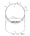
- the cross-sectional shape of the discharge opening 36 does not remain round as at the first end 18 of the discharge chute 16, since the lower and upper surfaces 30, 32 of the discharge chute 16 are not parallel to each other. Since the angle A is greater than the angle B is the height of the discharge opening 36 at the second end 20 of the Delivery duct 16 smaller than the height of the inlet opening 38 am first end 18 of the discharge shaft 16, as shown in Figure 2 can be seen.
- bottom surface 32 in FIG. 1 is substantially is shown flat or linear, it should be noted that the lower surface 32 could alternatively be curved while a Delivery angle B, which is smaller than the discharge angle A of the surface 30 is maintained.
- the dispensing tube 16 includes a trickle preventing door 40 which is secured within the tubular member. How best can be seen with reference to FIG 1, is the Rieselverhi matterssc 40 in the discharge chute 16 near the first end 18 by a Hinge 42 attached.
- the hinge 42 comprises a spring 44, so that the anti-trickle door 40 between a raised Position, as shown in Figure 1, and a lowered Position is pivotable.
- the spring 44 biases the Rieselverhindernse 40 usually in the upward position in front.
- the hinge 42 is connected by a hinge plate 46, which on Dispensing shaft 16 is attached in any suitable manner, the aligned, pivotable tubes 48, 50 on the hinge plate 46, by the anti-trickle door 40 and by the Hinge pin 52 defined by the pipes 48, 50 extends.
- the anti-trickle door 40 has opposite sides 54, which are curved upward, as seen in Figure 5, to matching with an area on the side wall of the Discharge shaft 16 to engage when the Rieselverhi concerningst 40 is in the upright position.
- the trickle preventing door 40 is also side to side curved, as best seen in Figure 3, to mating with the lower surface 32 of the delivery well 16 to engage when the Rieselverhi concerningsc 40 in the lowered position is moved.
- the discharge chute 16 directs grain 56 coming from the Entladeschnecken everydayer 12 is discharged, down in the Grain cart 34.
- the discharged grain 56 pivots the Rieselverhindernse 40 down, so that the Rieselverhi concerningse 40 the Flow of the discharged grain 56 does not limit. If the Screw conveyor 12 is turned off, so there is no rotation the inner driver (not shown) gives, breaks the flow of Korns 56 from, so that the Rieselverhi matterssc 40 by the Biasing the spring 44 back to its upright position is brought.
- the trickle preventing door thus prevents Grain trickling when the screw conveyor 12 is not actuated, for example, when the combine 10 is moving across the field or transported along a road.
Landscapes
- Life Sciences & Earth Sciences (AREA)
- Environmental Sciences (AREA)
- Engineering & Computer Science (AREA)
- Mechanical Engineering (AREA)
- Threshing Machine Elements (AREA)
Description
- Fig. 1
- eine vergrößerte seitliche Ansicht eines Abgabeschachts mit einer Rieselverhinderungstür,
- Fig. 2
- eine rückwärtige Ansicht des Abgabeschachts entlang der Linien 2-2 der Figur 1,
- Fig. 3
- eine perspektivische Ansicht der Rieselverhinde rungstür,
- Fig. 4
- eine seitliche Ansicht der Rieselverhinderungstür,
- Fig. 5
- eine Frontansicht der Rieselverhinderungstür, und
- Fig. 6
- eine perspektivische Ansicht eines Mähdreschers mit einem Entladeschneckenförderer, woran die Abgabeeinrichtung angebracht ist.
Claims (10)
- Mähdrescher (10) mit einem Schneckenförderer (12) und einem am Abgabeende (14) des Schneckenförderers (12) anbringbaren Abgabeschacht (16), wobei der Abgabeschacht (16) ein rohrförmiges Element mit einem ersten Ende (18) umfasst, das angepasst ist, am Abgabeende (14) des Schneckenförderers (12) angebracht zu werden, gekennzeichnet durch eine Rieselverhinderungstür (40), die innerhalb des rohrförmigen Elements zwischen einer geschlossenen und einer geöffneten Position schwenkbar angebracht ist und eine gekrümmte Oberfläche hat, um in der geöffneten und/oder geschlossenen Position zusammenpassend an einer benachbarten Oberfläche des rohrförmigen Elements anzugreifen.
- Mähdrescher (10) nach Anspruch 1, dadurch gekennzeichnet, dass die Rieselverhinderungstür zwischen einer angehobenen und einer abgesenkten Position beweglich ist.
- Mähdrescher (10) nach Anspruch 1 oder 2, dadurch gekennzeichnet, dass die Rieselverhinderungstür (40) nahe des ersten Endes (18) des rohrförmigen Elements angebracht ist.
- Mähdrescher (10) nach einem der Ansprüche 1 bis 3, dadurch gekennzeichnet, dass die Rieselverhinderungstür (40) stromauf des zweiten Endes (20) des rohrförmigen Elements angebracht ist.
- Mähdrescher (10) nach einem der Ansprüche 1 bis 4, gekennzeichnet durch eine Feder (44), die normalerweise die Rieselverhinderungstür (40) in die geschlossene Position verbringt.
- Mähdrescher (10) nach einem der vorhergehenden Ansprüche, dadurch gekennzeichnet, dass das rohrförmige Element eine obere Oberfläche (30) und eine untere Oberfläche (32) hat, wobei die obere Oberfläche (30) zur Produktabgabe nach unten unter einem ersten Winkel (A) endet, die untere Oberfläche (32) zur Produktabgabe nach unten unter einem zweiten Winkel (B) endet, und der erste Winkel (A) gegenüber einer horizontalen Fläche größer als der zweite Winkel (B) ist.
- Mähdrescher (10) nach einem der Ansprüche 1 bis 6, dadurch gekennzeichnet, dass die obere Oberfläche (30) des rohrförmigen Elements gekrümmt ist.
- Mähdrescher (10) nach einem der Ansprüche 1 bis 7, dadurch gekennzeichnet, dass die untere Oberfläche (32) des rohrförmigen Elements im Wesentlichen flach ist.
- Mähdrescher (10) nach einem der vorhergehenden Ansprüche, dadurch gekennzeichnet, dass das zweite Ende (20) des rohrförmigen Elements in der Nähe der unteren Oberfläche (32) breiter ist als in der Nähe der oberen Oberfläche (30).
- Mähdrescher (10) nach einem der vorhergehenden Ansprüche, dadurch gekennzeichnet, dass die Öffnung des ersten Endes (18) des rohrförmigen Elements eine größere Höhe hat als die Öffnung des zweiten Endes (20) des rohrförmigen Elements.
Applications Claiming Priority (2)
| Application Number | Priority Date | Filing Date | Title |
|---|---|---|---|
| US10/003,976 US6691861B2 (en) | 2001-10-25 | 2001-10-25 | Auger discharge chute with dribble door |
| US3976 | 2001-10-25 |
Publications (2)
| Publication Number | Publication Date |
|---|---|
| EP1306325A1 EP1306325A1 (de) | 2003-05-02 |
| EP1306325B1 true EP1306325B1 (de) | 2005-12-28 |
Family
ID=21708493
Family Applications (1)
| Application Number | Title | Priority Date | Filing Date |
|---|---|---|---|
| EP02102475A Expired - Lifetime EP1306325B1 (de) | 2001-10-25 | 2002-10-23 | Abgabeschacht für einen Schneckenförderer |
Country Status (4)
| Country | Link |
|---|---|
| US (1) | US6691861B2 (de) |
| EP (1) | EP1306325B1 (de) |
| DE (1) | DE50205420D1 (de) |
| DK (1) | DK1306325T3 (de) |
Families Citing this family (16)
| Publication number | Priority date | Publication date | Assignee | Title |
|---|---|---|---|---|
| BRPI0508000A (pt) * | 2004-03-26 | 2007-07-03 | Martin Eng Co | método e aparelho para desviar material |
| CA2533244C (en) * | 2006-01-18 | 2013-07-16 | Rem Manufacturing Ltd. | Auger airlock assembly and end dump housing |
| US7584836B2 (en) * | 2006-12-20 | 2009-09-08 | Cnh America Llc | Positive operating combine unloader discharge door arrangement |
| US7527555B2 (en) * | 2007-06-07 | 2009-05-05 | Cnh America Llc | Grain unloader conveyor tube with dribble control door |
| US7644816B2 (en) * | 2008-04-30 | 2010-01-12 | Cnh America Llc | Grain saving, directable unloader boot assembly |
| US7938613B2 (en) * | 2009-04-15 | 2011-05-10 | Cnh America Llc | Grain unloading conveyor with directable spout and closure apparatus and system |
| US8265837B2 (en) * | 2009-07-31 | 2012-09-11 | Cnh America Llc | Positive open grain saving unloading system |
| US9468145B2 (en) * | 2012-10-19 | 2016-10-18 | Cnh Industrial America Llc | Seal for unloading conveyor arrangement |
| US9038814B2 (en) | 2012-11-08 | 2015-05-26 | Cnh Industrial America Llc | Grain saver catch for an agricultural combine |
| CN103688675A (zh) * | 2013-12-24 | 2014-04-02 | 湖州丰源农业装备制造有限公司 | 一种收割机防漏粮结构 |
| US20160057927A1 (en) * | 2014-08-29 | 2016-03-03 | Agco International Gmbh | Grain unloading auger with dribble control door |
| DE202014104100U1 (de) | 2014-09-02 | 2014-09-09 | Agco International Gmbh | Erntegut-Entladesystem für eine Erntemaschine |
| EP3445154B1 (de) | 2016-05-28 | 2020-03-11 | Husqvarna AB | Rasenpflegefahrzeug mit fördererdichtung |
| US10645875B2 (en) * | 2017-10-19 | 2020-05-12 | Cnh Industrial America Llc | Method and system for unloading harvested crop from an agricultural harvester |
| GB201806796D0 (en) * | 2018-04-26 | 2018-06-13 | Agco Int Gmbh | Auger cover |
| USD964194S1 (en) * | 2020-08-28 | 2022-09-20 | E. Strode Pennebaker, III | Sloped wireless sensor system |
Family Cites Families (16)
| Publication number | Priority date | Publication date | Assignee | Title |
|---|---|---|---|---|
| US929514A (en) | 1909-03-09 | 1909-07-27 | Ole A Tenold | Sewer and drain-tile outlet protector. |
| US1505188A (en) | 1922-09-23 | 1924-08-19 | Henry J Burns | Feed regulator |
| US1615334A (en) | 1925-09-21 | 1927-01-25 | Ji Case Threshing Machine Co | Combination harvester thrasher |
| US1847433A (en) | 1931-05-02 | 1932-03-01 | Case Co J I | Conveyer |
| US2551461A (en) | 1944-12-26 | 1951-05-01 | Int Harvester Co | Bagger attachment for harvesters with swingably mounted bag supports |
| US2487693A (en) | 1948-06-18 | 1949-11-08 | Deward Bradley J | Grain gate |
| US2818163A (en) | 1955-05-16 | 1957-12-31 | Int Harvester Co | Recirculating conveyor |
| GB1091284A (en) * | 1963-11-07 | 1967-11-15 | Norton Harty Engineering Compa | Improvements in or relating to bunkers |
| US3447669A (en) | 1967-03-24 | 1969-06-03 | Martin Mayrath | Auger conveyor discharge unit with safety outlet |
| US4104812A (en) * | 1976-10-12 | 1978-08-08 | John J. Stribiak, Jr. | Snow blower for powered lawn mowers |
| US4334603A (en) * | 1980-07-28 | 1982-06-15 | Acurex Corporation | Article decelerating assembly and method |
| DE3227814C1 (de) * | 1982-07-26 | 1983-11-17 | Kali Und Salz Ag, 3500 Kassel | Einlauftrichter aus elektrisch isolierendem Material fuer elektrostatische Freifallscheider |
| US4540086A (en) | 1984-04-16 | 1985-09-10 | David Gary L | Grain auger closing spout |
| US4862607A (en) * | 1988-10-03 | 1989-09-05 | Outboard Marine Corporation | Remote controlled snowthrower discharge chute deflector |
| US5108249A (en) * | 1990-07-23 | 1992-04-28 | Kinze Manufacturing, Inc. | Gravity fed, chain conveyer for grain cart |
| CA2100907A1 (en) | 1993-07-20 | 1995-01-21 | Karl F. Seemann | No-nest bird gate |
-
2001
- 2001-10-25 US US10/003,976 patent/US6691861B2/en not_active Expired - Fee Related
-
2002
- 2002-10-23 DE DE50205420T patent/DE50205420D1/de not_active Expired - Fee Related
- 2002-10-23 DK DK02102475T patent/DK1306325T3/da active
- 2002-10-23 EP EP02102475A patent/EP1306325B1/de not_active Expired - Lifetime
Also Published As
| Publication number | Publication date |
|---|---|
| US20030079956A1 (en) | 2003-05-01 |
| US6691861B2 (en) | 2004-02-17 |
| DE50205420D1 (de) | 2006-02-02 |
| DK1306325T3 (da) | 2006-05-22 |
| EP1306325A1 (de) | 2003-05-02 |
Similar Documents
| Publication | Publication Date | Title |
|---|---|---|
| EP1306325B1 (de) | Abgabeschacht für einen Schneckenförderer | |
| DE60007778T2 (de) | Stahlbehälter, insbesondere für den transport von schüttgütern | |
| DE2728162A1 (de) | Korntank-entleerungsvorrichtung fuer maehdrescher | |
| DE2746704A1 (de) | Maehdrescher mit einer erntebergungsvorrichtung | |
| DE2532765A1 (de) | Vorrichtung zum verteilen teilchenfoermigen materials auf dem erdboden | |
| EP2020175B1 (de) | Erntemaschine mit verstellbarer Überladeeinrichtung | |
| DE3840826C2 (de) | ||
| DE69816754T2 (de) | Landwirtschaftliche Maschine mit Aufzugsystem | |
| EP0374418A1 (de) | Vorrichtung zur Herstellung gebrauchsfertiger Mischungen aus Schüttgut, wie z.B. Zement und Sand | |
| DE19822011C1 (de) | Austragvorrichtung für Getreidetrockner | |
| EP1425954B1 (de) | Reinigungseinrichtung für ein Entladerohr einer Erntemaschine | |
| DE69800150T2 (de) | Hydraulische Verbindungsvorrichtung für einen auf zwei unterschiedliche Höhen positionierbaren Geschirrkorb | |
| DE69201641T2 (de) | Fahrzeug für den Transport von pulverförmigem, körnigem oder pelletförmigem Schüttgut sowie Verfahren zum Entladen eines solchen Fahrzeugs. | |
| DE4419435A1 (de) | Fördervorrichtung für den Korntank eines Mähdreschers | |
| DE69111836T2 (de) | Abgabe-Ausgang für Fiberproduktemischer. | |
| EP0109518B1 (de) | Schneckenfördereinrichtung | |
| DE102006062328B3 (de) | Scheibenschar | |
| DE3248751A1 (de) | Vorrichtung zum streuen von schuettfaehigem gut | |
| DE3901774C2 (de) | Mischer mit einem Mischbehälter, insbesondere für Schüttgut | |
| DE19629957C2 (de) | Landwirtschaftliche Erntemaschine | |
| DE3040814C2 (de) | Einlaufschurre mit Verschlußvorrichtung für Wendelrutschen des Untertagebergbaues | |
| DE3502342C2 (de) | Einrichtung zum Sammeln und Fördern von Schüttgut | |
| DE3515362A1 (de) | Vorrichtung zum streuen von schuettfaehigem gut, insbesondere duenger | |
| DE9000053U1 (de) | Injektionsvorrichtung zur kontinuierlichen Einbringung von Flüssigdünger od.dgl. in den Boden | |
| DE20219176U1 (de) | Schurre zur Gutübergabe von Gutaufnahmeorganen auf einen Senkrechtförderer für einen kontinuierlichen Schiffsentlader |
Legal Events
| Date | Code | Title | Description |
|---|---|---|---|
| PUAI | Public reference made under article 153(3) epc to a published international application that has entered the european phase |
Free format text: ORIGINAL CODE: 0009012 |
|
| AK | Designated contracting states |
Designated state(s): AT BE BG CH CY CZ DE DK EE ES FI FR GB GR IE IT LI LU MC NL PT SE SK TR |
|
| AX | Request for extension of the european patent |
Extension state: AL LT LV MK RO SI |
|
| 17P | Request for examination filed |
Effective date: 20031103 |
|
| AKX | Designation fees paid |
Designated state(s): BE DE DK FR GB |
|
| 17Q | First examination report despatched |
Effective date: 20031211 |
|
| GRAP | Despatch of communication of intention to grant a patent |
Free format text: ORIGINAL CODE: EPIDOSNIGR1 |
|
| GRAS | Grant fee paid |
Free format text: ORIGINAL CODE: EPIDOSNIGR3 |
|
| GRAA | (expected) grant |
Free format text: ORIGINAL CODE: 0009210 |
|
| AK | Designated contracting states |
Kind code of ref document: B1 Designated state(s): BE DE DK FR GB |
|
| REG | Reference to a national code |
Ref country code: GB Ref legal event code: FG4D Free format text: NOT ENGLISH |
|
| REF | Corresponds to: |
Ref document number: 50205420 Country of ref document: DE Date of ref document: 20060202 Kind code of ref document: P |
|
| GBT | Gb: translation of ep patent filed (gb section 77(6)(a)/1977) |
Effective date: 20060126 |
|
| REG | Reference to a national code |
Ref country code: DK Ref legal event code: T3 |
|
| ET | Fr: translation filed | ||
| PLBE | No opposition filed within time limit |
Free format text: ORIGINAL CODE: 0009261 |
|
| STAA | Information on the status of an ep patent application or granted ep patent |
Free format text: STATUS: NO OPPOSITION FILED WITHIN TIME LIMIT |
|
| 26N | No opposition filed |
Effective date: 20060929 |
|
| PGFP | Annual fee paid to national office [announced via postgrant information from national office to epo] |
Ref country code: DE Payment date: 20080919 Year of fee payment: 7 Ref country code: DK Payment date: 20081030 Year of fee payment: 7 |
|
| PGFP | Annual fee paid to national office [announced via postgrant information from national office to epo] |
Ref country code: BE Payment date: 20081112 Year of fee payment: 7 |
|
| PGFP | Annual fee paid to national office [announced via postgrant information from national office to epo] |
Ref country code: FR Payment date: 20081018 Year of fee payment: 7 |
|
| PGFP | Annual fee paid to national office [announced via postgrant information from national office to epo] |
Ref country code: GB Payment date: 20081029 Year of fee payment: 7 |
|
| BERE | Be: lapsed |
Owner name: *DEERE & CY Effective date: 20091031 |
|
| REG | Reference to a national code |
Ref country code: DK Ref legal event code: EBP |
|
| REG | Reference to a national code |
Ref country code: FR Ref legal event code: ST Effective date: 20100630 |
|
| PG25 | Lapsed in a contracting state [announced via postgrant information from national office to epo] |
Ref country code: FR Free format text: LAPSE BECAUSE OF NON-PAYMENT OF DUE FEES Effective date: 20091102 Ref country code: DE Free format text: LAPSE BECAUSE OF NON-PAYMENT OF DUE FEES Effective date: 20100501 |
|
| PG25 | Lapsed in a contracting state [announced via postgrant information from national office to epo] |
Ref country code: BE Free format text: LAPSE BECAUSE OF NON-PAYMENT OF DUE FEES Effective date: 20091031 |
|
| PG25 | Lapsed in a contracting state [announced via postgrant information from national office to epo] |
Ref country code: GB Free format text: LAPSE BECAUSE OF NON-PAYMENT OF DUE FEES Effective date: 20091023 |
|
| PG25 | Lapsed in a contracting state [announced via postgrant information from national office to epo] |
Ref country code: DK Free format text: LAPSE BECAUSE OF NON-PAYMENT OF DUE FEES Effective date: 20091031 |