EP1306305A2 - Diagnosesystem sowie Diagnoseverfahren zur Unterstützung der Flugzeugwartung - Google Patents
Diagnosesystem sowie Diagnoseverfahren zur Unterstützung der Flugzeugwartung Download PDFInfo
- Publication number
- EP1306305A2 EP1306305A2 EP02023950A EP02023950A EP1306305A2 EP 1306305 A2 EP1306305 A2 EP 1306305A2 EP 02023950 A EP02023950 A EP 02023950A EP 02023950 A EP02023950 A EP 02023950A EP 1306305 A2 EP1306305 A2 EP 1306305A2
- Authority
- EP
- European Patent Office
- Prior art keywords
- sensor
- diagnostic system
- signals
- diagnostic
- processing unit
- Prior art date
- Legal status (The legal status is an assumption and is not a legal conclusion. Google has not performed a legal analysis and makes no representation as to the accuracy of the status listed.)
- Granted
Links
Images


Classifications
-
- G—PHYSICS
- G07—CHECKING-DEVICES
- G07C—TIME OR ATTENDANCE REGISTERS; REGISTERING OR INDICATING THE WORKING OF MACHINES; GENERATING RANDOM NUMBERS; VOTING OR LOTTERY APPARATUS; ARRANGEMENTS, SYSTEMS OR APPARATUS FOR CHECKING NOT PROVIDED FOR ELSEWHERE
- G07C5/00—Registering or indicating the working of vehicles
- G07C5/08—Registering or indicating performance data other than driving, working, idle, or waiting time, with or without registering driving, working, idle or waiting time
- G07C5/0841—Registering performance data
- G07C5/085—Registering performance data using electronic data carriers
-
- B—PERFORMING OPERATIONS; TRANSPORTING
- B60—VEHICLES IN GENERAL
- B60C—VEHICLE TYRES; TYRE INFLATION; TYRE CHANGING; CONNECTING VALVES TO INFLATABLE ELASTIC BODIES IN GENERAL; DEVICES OR ARRANGEMENTS RELATED TO TYRES
- B60C23/00—Devices for measuring, signalling, controlling, or distributing tyre pressure or temperature, specially adapted for mounting on vehicles; Arrangement of tyre inflating devices on vehicles, e.g. of pumps or of tanks; Tyre cooling arrangements
- B60C23/02—Signalling devices actuated by tyre pressure
- B60C23/04—Signalling devices actuated by tyre pressure mounted on the wheel or tyre
- B60C23/0408—Signalling devices actuated by tyre pressure mounted on the wheel or tyre transmitting the signals by non-mechanical means from the wheel or tyre to a vehicle body mounted receiver
- B60C23/0479—Communicating with external units being not part of the vehicle, e.g. tools for diagnostic, mobile phones, electronic keys or service stations
-
- B—PERFORMING OPERATIONS; TRANSPORTING
- B64—AIRCRAFT; AVIATION; COSMONAUTICS
- B64D—EQUIPMENT FOR FITTING IN OR TO AIRCRAFT; FLIGHT SUITS; PARACHUTES; ARRANGEMENTS OR MOUNTING OF POWER PLANTS OR PROPULSION TRANSMISSIONS IN AIRCRAFT
- B64D47/00—Equipment not otherwise provided for
-
- B—PERFORMING OPERATIONS; TRANSPORTING
- B64—AIRCRAFT; AVIATION; COSMONAUTICS
- B64F—GROUND OR AIRCRAFT-CARRIER-DECK INSTALLATIONS SPECIALLY ADAPTED FOR USE IN CONNECTION WITH AIRCRAFT; DESIGNING, MANUFACTURING, ASSEMBLING, CLEANING, MAINTAINING OR REPAIRING AIRCRAFT, NOT OTHERWISE PROVIDED FOR; HANDLING, TRANSPORTING, TESTING OR INSPECTING AIRCRAFT COMPONENTS, NOT OTHERWISE PROVIDED FOR
- B64F5/00—Designing, manufacturing, assembling, cleaning, maintaining or repairing aircraft, not otherwise provided for; Handling, transporting, testing or inspecting aircraft components, not otherwise provided for
- B64F5/60—Testing or inspecting aircraft components or systems
-
- G—PHYSICS
- G07—CHECKING-DEVICES
- G07C—TIME OR ATTENDANCE REGISTERS; REGISTERING OR INDICATING THE WORKING OF MACHINES; GENERATING RANDOM NUMBERS; VOTING OR LOTTERY APPARATUS; ARRANGEMENTS, SYSTEMS OR APPARATUS FOR CHECKING NOT PROVIDED FOR ELSEWHERE
- G07C3/00—Registering or indicating the condition or the working of machines or other apparatus, other than vehicles
-
- G—PHYSICS
- G07—CHECKING-DEVICES
- G07C—TIME OR ATTENDANCE REGISTERS; REGISTERING OR INDICATING THE WORKING OF MACHINES; GENERATING RANDOM NUMBERS; VOTING OR LOTTERY APPARATUS; ARRANGEMENTS, SYSTEMS OR APPARATUS FOR CHECKING NOT PROVIDED FOR ELSEWHERE
- G07C5/00—Registering or indicating the working of vehicles
- G07C5/006—Indicating maintenance
-
- G—PHYSICS
- G07—CHECKING-DEVICES
- G07C—TIME OR ATTENDANCE REGISTERS; REGISTERING OR INDICATING THE WORKING OF MACHINES; GENERATING RANDOM NUMBERS; VOTING OR LOTTERY APPARATUS; ARRANGEMENTS, SYSTEMS OR APPARATUS FOR CHECKING NOT PROVIDED FOR ELSEWHERE
- G07C5/00—Registering or indicating the working of vehicles
- G07C5/008—Registering or indicating the working of vehicles communicating information to a remotely located station
Definitions
- the invention relates to a diagnostic system and a diagnostic method for Aircraft maintenance support.
- Extensive maintenance checks are currently being carried out at predetermined, regular intervals for the maintenance of aircraft.
- the components of the individual aircraft systems are checked regularly and / or replaced after a certain period of use. Due to the large number and complexity of the parts to be checked, it is often complex to remove the respective component, to carry out an error check and check the functionality and to reinstall it or to replace it with a new device. Errors may also occur during a flight that are not recognized during a ground check. For example, wear in the actuators of the wing flap systems can cause the entire aircraft to vibrate due to control vibrations. This error is then usually not reproducible on the ground, the faulty actuator cannot be located safely and, for safety reasons, functional actuators may also be replaced, which causes considerable costs. Maintenance costs are therefore an essential part of the ongoing operating costs of commercial aircraft.
- the object of the invention is therefore to support maintenance of a commercial aircraft a quick and safe location of errors as well a corresponding provision of information for the maintenance personnel to realize as little effort as possible and thus a shortening to reach the repair time.
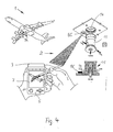
- a commercial aircraft 1 located on the ground can be seen in a schematic illustration in FIG. 1.
- a so-called "walk around” check must be carried out, ie a mechanic checks the functionality of important systems. For this - as indicated in the arrows - a round trip around the entire aircraft is necessary and important aircraft systems and aircraft components are checked, for example tests are carried out on the nose wheel 3A and landing gear wheels 3B with a query of the air pressure and a check of the brakes.
- the flap systems 4 and 4 ' such as spoilers and landing flaps and the hydraulic actuators required for the adjustment, are also checked, for example denoted by 5.
- a mechanic commissioned with the ground check receives a hand-held device 6 as part of a diagnostic system 2 as work equipment, which on the one hand shows the maintenance information required for a special maintenance task (checklist with points to be processed) on a display 7 and queries diagnostic information of maintenance-intensive aircraft systems can.
- the maintenance information can be made available comprehensively on the hand-held device 6, preferably by means of an exchangeable storage medium.
- a connection of the hand-held device 6 to a stationary unit for example a personal computer or a server, is provided, the connection being made via a suitable interface which is to be selected in accordance with the amount of data to be transmitted.
- Sensor devices 8 are provided on the aircraft systems to be serviced in order to record diagnostic information.
- sensors are provided on the hydraulic actuators 5 and 5 'in order to be able to detect actuator defects. The sensor information is queried and evaluated during a floor check, and a fault diagnosis (locally determined actuator in order or faulty) is shown on the display 7 of the handheld device 6.
- An embodiment for diagnosing actuators is described in more detail in FIG. 2.
- the sensor devices 8 can also be used to query the water concentration, the particle concentration or level in hydraulic systems or Fuel will be provided. Embodiments of this type are shown in FIGS. 3 and 4 specified.
- a Processing unit 9 For checking the aircraft systems during a ground check the corresponding sensor signals via transmission devices to a Processing unit 9 sent and processed there and on a Display unit 10 provided as information for the mechanic.
- the processing unit 9 receives the wirelessly with a receiver 11 Sensor signals. Processing of the information can be done by means of usual stationary computers or directly in a preferred embodiment Pocket PCs or laptops are made and made available to the mechanic become. It is preferably provided that the hand-held device 6 is used as a work tool for the mechanic, in addition to the display device 10, the Contains processing unit 9 and thus it immediately and on site Check the aircraft components and carry out a fault diagnosis can.
- a signal transmission from the Sensor device 8 to the processing unit 9 wirelessly via a larger one Range, approximately over a distance of at least 12 m, is possible.
- a Signal transmission is possible, for example, with radio connections or Infrared signals.
- the necessary for signal generation and signal transmission Energy is made available in the area of the sensor devices 8.
- the Sensor devices 8 are preferably without intervention in existing ones Aircraft systems trained energy self-sufficient. This ensures that an integration of the sensor devices 8 in the aircraft Functionality of the existing aircraft systems is not impaired and no additional connection to the energy supply of the aircraft necessary is.
- the energy supply of the sensor devices 8 can provided for example via separate energy sources or energy stores his. Energy generators from the environment should preferably be used Generate energy, such as from vibration. This is shown Energy self-sufficient diagnostic sensors with the option of active wireless Query 80 in Figure 1A.
- the sensor device 8 comprises a transmitter / receiver unit (Receiver / Transmitter) 81, a sensor 82 and one Microcontroller (C, signal converter A / DC, Time) 83 for data acquisition and for example also of time. If a query signal on the handset 6 is triggered, the data is transmitted to the transmitter / receiver unit (Receiver / Transmitter) 11 of the handheld device 6.
- the processing unit 9 with the display device (Display and Controll) and with a microprocessor-based interface (Controlled Interface) and can perform at least some of the following functions: Show work progress, wirelessly query sensor devices, register and display of data, exchange of data and instructions and / or show visualized repair instructions.
- a wireless query 80 of sensor devices 8 can be passive wireless query 84 by the handheld device 6. Here they need Sensors do not have their own energy.
- During the query is on a shorter Distance, for example ⁇ 0.1 m, starting from a transceiver 85 Sensor identified and an HF (rf [radio-frequency]) transponder 86 activated, performed a sensor query and this measured value to the transceiver 85 transmitted.
- a measurement of the air pressure in tires is included can be measured and transmitted using this method.
- the energy required is here taken from the transmission power.
- Another embodiment of the invention uses sensor devices as diagnostic sensors that have active storage of the measured value. The energy required for this can be very low.
- the storage value is called up with the passive wireless mentioned Query 84, the energy required from the transmission power of the Transceivers 85 is provided.
- optical transponders the optical active or passive queries enable.
- FIG. 2 shows an embodiment of the diagnostic system in the range of Actuators for flap systems 4, 4 'on the wings of the Commercial aircraft 1 shown.
- a variety of actuators 5 are for the Adjustment of the wing flaps is necessary and there is wear on the actuators check regularly. Wear of the spoiler actuators 5 can occur For example, cause the entire aircraft to fly in individual phases is vibrated by control vibrations (called the slipping effect). On the ground, this error is usually no longer reproducible and one exact determination of the faulty actuators can be done with the help of the Corresponding actuator 5 arranged sensor device 8A made the measurement data are recorded during the flight, if necessary processed and saved. A preprocessing of the sensor signal can be within a preprocessing module of the sensor device 8 be advantageous to achieve a data reduction.
- a sensor like for example a piezo sensor (enables signal generation based on mechanical pressure) and / or an acceleration sensor is at least one of those that occur when diagnosing vibrations (slipping effect) significant parameters, e.g. B. hydraulic control pressure surges or control piston oscillation measured, stored, possibly pre-processed - i.e. just certain dates or interim results are used for the further process required - and these are saved and wirelessly sent to the Processing unit 9 transmitted.
- the mechanic can on the display 7 of the Handheld device 6 the corresponding diagnostic information of the respective actuator 5 query and make a confident decision whether due to slipping effects Replacement of the actuator 5 is necessary. Since a large number of actuators 5 it will be used for the movement of the flaps on the commercial aircraft with the exact location of defective actuators enables an exchange or already the complex expansion and testing of a functional spoiler actuator to avoid.
- FIG. 3 shows an embodiment of the diagnostic system 2 in the area of a Hydraulic system for actuators in the commercial aircraft 1 shown.
- a hydraulic tank 12 which in the embodiment shown in the area of Landing gear shaft 13 of the aircraft 1 is arranged regularly Determine the water content of the hydraulic fluid, because of water entry the lifespan of hydraulic fluid is significantly reduced. A high one Water content leads to damage to the entire hydraulic system.
- the sensor device 8B is for this application to measure the Concentration of water in the hydraulic tank at the bottom of the Container 12 arranged.
- the measured variables are transmitted via transmitters the processing unit 9 in the handheld device 6 is transmitted.
- the mechanic who should carry out a condition diagnosis of the hydraulic fluid on Display 7 read the diagnostic information, for example the water content. He does not have to get into the landing gear shaft through the access flap and Take 12 measurements directly on the hydraulic reservoir.
- FIG. 4 shows an embodiment of the diagnostic system 2 in the area of a Fuel tanks 14 shown in the commercial aircraft 1.
- Water deposits in the Fuel tank 14 must be removed regularly.
- one Water drainage valve 15 is provided. Close to this valve 15 is a fuel water detection sensor 8C arranged within the tank 14.
- the Sensor device 8C the amount of water in the tank or the water level can measure the amount of water deposited and to the processing unit 9 transmitted, the maintenance personnel can diagnose the water level the display device 10 (display 7) can be communicated.
- the time for one necessary water drainage can thus be determined relatively precisely and the necessary work only needs to be carried out as required. How already explained in relation to the previous embodiments, also takes place here the transmission of the measurement signals from the sensor device 8C to Processing unit 9 wireless.
- the handheld device 6 on the display 7 takes place at a request for the diagnostic information by the maintenance personnel Remote inquiry of the water level in the tank 14.
- the signal is from the fuel water Detection sensor 8C transmitted to the processing unit 9 and by means of a Evaluation software processes the measured value and as diagnostic information edited. In a preferred embodiment, depending on the Evaluation software also shows the mechanic whether the a water drain is necessary.
- Such maintenance information can depending on the application of the diagnostic system comprehensively on the handheld device 6, preferably through a removable storage medium be put.
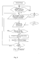
- FIG. 5 shows an example of a flow chart with the representation of a diagnostic query.
- Sensor signals are present at a sensor device 8 and can be called up from the handheld device 6 by a correspondingly addressed request. If a query was unsuccessful and no response was received within a certain time, for example 10 ms, the query is repeated. The sensor signals are transmitted to the processing unit 9, processed, the result stored and displayed as required. After the query has been completed, a new query of a next diagnostic sensor system can be carried out.
- the present invention is not based on the mentioned exemplary embodiments limited, rather the use of the invention for a sensor-based Maintenance support on many aircraft components or Aircraft systems possible.
- Maintenance-intensive system components i.e. Components that are due to frequent failure or safety relevance can be checked frequently with the present invention be equipped or checked, what the maintenance effort for this Components significantly reduced.
Abstract
Description
Die Wartungskosten sind demnach ein wesentlicher Bestandteil der laufenden Betriebskosten von Verkehrsflugzeugen.
- Fig. 1
- eine schematische Darstellung eines Flugzeuges beim "Walk Around Check",
- Fig. 1A
- Darstelllung der Funktionsweise einer energieautarken Diagnose-Sensorik,
- Fig. 2
- die Darstellung einer Fehlerdiagnose bei Aktuatoren im Flügelbereich eines Verkehrsflugzeuges,
- Fig. 3
- die Darstellung einer Diagnose von Wassergehalt im Hydrauliksystem des Flugzeuges,
- Fig. 4
- die Darstellung einer Diagnose vom Wassergehalt im Treibstoff eines Flugzeugtanksystems und
- Fig. 5
- die Darstellung eines Ablaufs einer Diagnoseabfrage.
Zur Erfassung von Diagnoseinformationen sind Sensoreinrichtungen 8 an den zu wartenden Flugzeugsystemen vorgesehen. Beispielsweise sind Sensoren an den Hydraulikaktuatoren 5 und 5' vorgesehen, um Aktuatordefekte detektieren zu können. Die Sensorinformationen werden während eines Bodenchecks abgefragt, ausgewertet und eine Fehlerdiagnose (örtlich bestimmter Aktuator in Ordnung bzw. fehlerhaft) wird auf dem Display 7 des Handgeräts 6 angezeigt. Eine Ausführungsform zur Diagnose von Aktuatoren ist näher in der Fig. 2 beschrieben.
Nach Erledigung der Abfrage kann eine neue Abfrage einer nächsten Diagnose-Sensorik durchgeführt werden.
Claims (21)
- Diagnosesystem zur Unterstützung der Flugzeugwartung eines Verkehrsflugzeuges, dadurch gekennzeichnet, dass
zumindest eine Sensoreinrichtung (8) zur Erzeugung und Speicherung von Sensorsignalen an zumindest einem Überprüfungsort zur Diagnose von Fehlern an wartungsintensiven Flugzeugsystemen vorgesehen ist, wobei die Sensorsignale an eine Verarbeitungseinheit (9) übermittelbar sind und die Verarbeitungseinheit (9) mit einer Anzeigeeinrichtung (10) mit Anzeige der Sensorsignale und/oder der ermittelten Diagnoseinformationen in Wirkverbindung steht. - Diagnosesystem nach Anspruch 1,
dadurch gekennzeichnet, dass
die Sensoreinrichtung (8) ein Verarbeitungsmodul zur Vorverarbeitung der Sensorsignale innerhalb der Sensoreinrichtung (8) aufweist, wobei die Sensorsignale innerhalb des Verarbeitungsmoduls in Auswerte- bzw. Zwischensignale verarbeitet werden. - Diagnosesystem nach einem der Ansprüche 1 oder 2,
dadurch gekennzeichnet, dass
die Sensoreinrichtung (10) energieautark zu den vorhandenen Flugzeugsystemen bzw. -komponenten ausgebildet ist. - Diagnosesystem nach Anspruch 3,
dadurch gekennzeichnet, dass
die Sensoreinrichtung (10) mit einem Energiegenerator und/oder einem Energiespeicher ausgestattet ist. - Diagnosesystem nach einem der Ansprüche 1 bis 4,
dadurch gekennzeichnet, dass
die Sensoreinrichtung (8) kabellos zur Übermittlung der Sensorsignale mit einem Empfänger (11) der Verarbeitungseinheit (9) in Wirkverbindung steht. - Diagnosesystem nach einem der Ansprüche 1 bis 5,
dadurch gekennzeichnet, dass
die Sensoreinrichtung (8) einen HF-Transponder (84) zur passiven drahtlosen Abfrage von Sensorsignalen aufweist. - Diagnosesystem nach einem der Ansprüche 4 oder 6,
dadurch gekennzeichnet, dass
die Sensoreinrichtung (8) ein aktives Speichermittel zur Speicherung eines Sensorsignals sowie einen Transponder (84) zur passiven drahtlosen Abfrage von Sensorsignalen aufweist. - Diagnosesystem nach einem der Ansprüche 1 bis 7,
dadurch gekennzeichnet, dass
die Sensoreinrichtung (8) zumindest einen optischen Transponder aufweist zur optischen aktiven bzw. passiven Abfrage. - Diagnosesystem nach einem der Ansprüche 5 bis 8,
dadurch gekennzeichnet, dass
die Übermittlung der Sensorsignale mittels Funk- oder Infraroteinrichtungen vorgesehen ist. - Diagnosesystem nach einem der Ansprüche 1 bis 9,
dadurch gekennzeichnet, dass
die Verarbeitungseinheit (9) Mittel zur Auswertung der Sensorsignale für eine Fehlerdiagnose enthält. - Diagnosesystem nach einem der Ansprüche 1 bis 10,
dadurch gekennzeichnet, dass
die Verarbeitungseinheit (9) ein Speichermedium zur Speicherung von Diagnoseinformationen sowie von für eine Wartungsaufgabe notwendige Wartungsinformationen aufweist. - Diagnosesystem nach einem der Ansprüche 1 bis 11,
dadurch gekennzeichnet, dass
eine Anzeigeeinrichtung (10) ein Display (7) zur Anzeige von Diagnoseinformationen sowie von für eine Wartungsaufgabe notwendige Wartungsinformationen aufweist. - Diagnosesystem nach einem der Ansprüche 1 bis 12,
dadurch gekennzeichnet, dass
die Verarbeitungseinheit (9) sowie die Anzeigeeinrichtung (10) in einem Handgerät (6) zusammengefasst sind. - Diagnosesystem nach einem der Ansprüche 1 bis 13,
dadurch gekennzeichnet, dass
das Handgerät (6) an eine stationäre Computerstation, beispielsweise ein Personalcomputer und/oder ein Server, anschließbar ist. - Diagnosesystem nach einem der Ansprüche 1 bis 14,
dadurch gekennzeichnet, dass
die Sensoreinrichtung (8, 8A) an Hydraulikaktuatoren (5, 5') von Flügelklappen (4, 4') zur Ermittlung des Aktuatorverschleißes vorgesehen ist. - Diagnosesystem nach einem der Ansprüche 1 bis 15,
dadurch gekennzeichnet, dass
die Sensoreinrichtung (8, 8B) im unteren Bereich des Hydraulikbehälters (12) zur Ermittlung des Wassergehalts und/oder der Partikelkonzentration vorgesehen ist. - Diagnosesystem nach einem der Ansprüche 1 bis 16,
dadurch gekennzeichnet, dass
die Sensoreinrichtung (8, 8C) im Flugzeugtank (14) im Bereich des Wasserdrainageventils (15) zur Ermittlung der Wasserkonzentration vorgesehen ist. - Diagnoseverfahren zur Unterstützung der Flugzeugwartung eines Verkehrsflugzeuges,
dadurch gekennzeichnet, dass
an wartungsintensiven Flugzeugsystemen bzw. -komponenten (5,5';12;14) an einem Überprüfungsort in einer Sensoreinrichtung (8) Sensorsignale erzeugt und gespeichert werden,
die Sensorsignale an eine Verarbeitungseinheit (9) übermittelt und dort verarbeitet werden,
selektierte Sensorsignale oder Auswertesignale an eine Anzeigeeinrichtung (10) übermittelt werden und
diese Diagnoseinformationen sowie gegebenenfalls für eine Wartungsaufgabe notwendige Wartungsinformationen an der Anzeigeeinrichtung (10) angezeigt werden. - Diagnoseverfahren nach Anspruch 18,
dadurch gekennzeichnet, dass
die Sensorsignale innerhalb der Sensoreinrichtung (8) zur Erreichung einer Datenreduktion vorverarbeitet werden und Auswerte- bzw. Zwischensignale an die Verarbeitungseinheit (9) übermittelt werden. - Diagnoseverfahren nach einem der Ansprüche 18 oder 19,
dadurch gekennzeichnet, dass
die Sensorsignale kabellos von der Sensoreinrichtung (8) zur Verarbeitungseinheit (9) übermittelt werden. - Diagnoseverfahren nach einem der Ansprüche 18 bis 20,
dadurch gekennzeichnet, dass
die an die Verarbeitungseinheit (9) übermittelten Signale (Sensorsignale bzw. bereits vorverarbeitete Zwischensignale) in Abhängigkeit von der notwendigen Wartungsaufgabe verarbeitet werden.
Applications Claiming Priority (2)
| Application Number | Priority Date | Filing Date | Title |
|---|---|---|---|
| DE10153151 | 2001-10-27 | ||
| DE10153151A DE10153151A1 (de) | 2001-10-27 | 2001-10-27 | Diagnosesystem sowie Diagnoseverfahren zur Unterstützung der Flugzeugwartung |
Publications (3)
| Publication Number | Publication Date |
|---|---|
| EP1306305A2 true EP1306305A2 (de) | 2003-05-02 |
| EP1306305A3 EP1306305A3 (de) | 2006-01-04 |
| EP1306305B1 EP1306305B1 (de) | 2009-05-27 |
Family
ID=7703973
Family Applications (1)
| Application Number | Title | Priority Date | Filing Date |
|---|---|---|---|
| EP02023950A Expired - Lifetime EP1306305B1 (de) | 2001-10-27 | 2002-10-25 | Flugzeugwartungsdiagnosesystem sowie Flugzeugwartungsdiagnoseverfahren |
Country Status (4)
| Country | Link |
|---|---|
| US (2) | US7050894B2 (de) |
| EP (1) | EP1306305B1 (de) |
| AT (1) | ATE432217T1 (de) |
| DE (2) | DE10153151A1 (de) |
Cited By (8)
| Publication number | Priority date | Publication date | Assignee | Title |
|---|---|---|---|---|
| EP1784726A2 (de) * | 2004-07-19 | 2007-05-16 | United Technologies Corporation | System und verfahren für ein fehlercodegesteuertes wartungssystem |
| GB2395565B (en) * | 2002-11-07 | 2007-06-06 | Nec Corp | Vehicle diagnostic system and method |
| EP1879153A2 (de) | 2006-06-26 | 2008-01-16 | Robert Bosch Gmbh | Verfahren und Vorrichtung zum Erfassen und/oder Übermitteln von Service- und Diagnosedaten eines Fahrzeugs an ein Werkstatt-Management-System |
| EP2166455A1 (de) | 2008-09-15 | 2010-03-24 | Airbus Operations | Verfahren und Vorrichtung zur Automatisierung von Prüfprozeduren für Flugzeugausstattung |
| FR2938675A1 (fr) * | 2008-11-14 | 2010-05-21 | Thales Sa | Dispositif permettant l'amelioration des procedures de maintenance d'equipements embarques |
| US9248918B2 (en) | 2009-04-16 | 2016-02-02 | Airbus Operations Gmbh | High lift system for an aircraft and method for detecting faults in a high lift system for an aircraft |
| CN105383696A (zh) * | 2015-10-20 | 2016-03-09 | 中国矿业大学 | 一种基于手机客户端空气质量监测飞行器 |
| EP2562090A3 (de) * | 2011-08-23 | 2016-04-27 | The Boeing Company | Systeme und Verfahren zur automatisierten Lokalisierung und Einstufung von Fehlern |
Families Citing this family (118)
| Publication number | Priority date | Publication date | Assignee | Title |
|---|---|---|---|---|
| DE10153151A1 (de) * | 2001-10-27 | 2003-05-15 | Airbus Gmbh | Diagnosesystem sowie Diagnoseverfahren zur Unterstützung der Flugzeugwartung |
| US20030154158A1 (en) * | 2001-11-14 | 2003-08-14 | Martyn Peter J. | Multi-mechanism order processing |
| US7027953B2 (en) * | 2002-12-30 | 2006-04-11 | Rsl Electronics Ltd. | Method and system for diagnostics and prognostics of a mechanical system |
| DE10326627A1 (de) * | 2003-06-11 | 2005-01-05 | Endress + Hauser Gmbh + Co. Kg | Verfahren zur Funktionsanzeige eines Feldgerätes der Prozessautomatisierungstechnik |
| US20050043870A1 (en) * | 2003-08-22 | 2005-02-24 | General Electric Company | Method and apparatus for recording and retrieving maintenance, operating and repair data for turbine engine components |
| FR2859556B1 (fr) * | 2003-09-05 | 2005-11-11 | Airbus France | Procede et dispositif de maintenance d'un equipement de radionavigation d'un aeronef |
| US7149612B2 (en) * | 2004-01-05 | 2006-12-12 | Arinc Incorporated | System and method for monitoring and reporting aircraft quick access recorder data |
| US7584420B2 (en) * | 2004-02-12 | 2009-09-01 | Lockheed Martin Corporation | Graphical authoring and editing of mark-up language sequences |
| US20050223288A1 (en) * | 2004-02-12 | 2005-10-06 | Lockheed Martin Corporation | Diagnostic fault detection and isolation |
| US20050240555A1 (en) * | 2004-02-12 | 2005-10-27 | Lockheed Martin Corporation | Interactive electronic technical manual system integrated with the system under test |
| US7801702B2 (en) * | 2004-02-12 | 2010-09-21 | Lockheed Martin Corporation | Enhanced diagnostic fault detection and isolation |
| JP4270017B2 (ja) * | 2004-04-15 | 2009-05-27 | 三菱自動車工業株式会社 | 車両の検査管理システム |
| US7283934B2 (en) * | 2004-07-28 | 2007-10-16 | Hr Textron, Inc. | Acceptance testing of actuators using predetermined thresholds |
| DE102004047241A1 (de) * | 2004-09-29 | 2006-04-06 | Abb Patent Gmbh | Verfahren und Einrichtung zur Diagnose von innerhalb einer industriellen Anlage angeordneten technischen Geräten |
| US20060120181A1 (en) * | 2004-10-05 | 2006-06-08 | Lockheed Martin Corp. | Fault detection and isolation with analysis of built-in-test results |
| US20060085692A1 (en) * | 2004-10-06 | 2006-04-20 | Lockheed Martin Corp. | Bus fault detection and isolation |
| US7821623B2 (en) * | 2004-11-16 | 2010-10-26 | The Boeing Company | Surveillance satellite image denial system |
| US20080052281A1 (en) * | 2006-08-23 | 2008-02-28 | Lockheed Martin Corporation | Database insertion and retrieval system and method |
| US20060142972A1 (en) * | 2004-12-29 | 2006-06-29 | Snap-On Incorporated | System and method of using sensors to emulate human senses for diagnosing an assembly |
| JP2006242707A (ja) * | 2005-03-02 | 2006-09-14 | Denso Corp | タイヤ空気圧検出装置 |
| FR2888362B1 (fr) * | 2005-07-05 | 2007-10-12 | Airbus France Sas | Outil de diagnostic pour la reparation d'aeronefs et procede utilisant cet outil |
| US7427025B2 (en) * | 2005-07-08 | 2008-09-23 | Lockheed Marlin Corp. | Automated postal voting system and method |
| US20070112487A1 (en) * | 2005-11-16 | 2007-05-17 | Avery Robert L | Integrated maintenance and materials service for fleet aircraft and system for determining pricing thereof |
| US7305327B2 (en) * | 2006-01-30 | 2007-12-04 | Sper Scientific Ltd | Wireless meter for real time measurements and method therefor |
| US7529603B2 (en) * | 2006-03-20 | 2009-05-05 | The Boeing Company | Integrated performance application |
| US7739007B2 (en) * | 2006-03-29 | 2010-06-15 | Snap-On Incorporated | Vehicle diagnostic method and system with intelligent data collection |
| US7979192B2 (en) * | 2006-03-31 | 2011-07-12 | Morrison Brian D | Aircraft-engine trend monitoring system |
| US8762165B2 (en) | 2006-06-14 | 2014-06-24 | Bosch Automotive Service Solutions Llc | Optimizing test procedures for a subject under test |
| US7765040B2 (en) * | 2006-06-14 | 2010-07-27 | Spx Corporation | Reverse failure analysis method and apparatus for diagnostic testing |
| US8423226B2 (en) * | 2006-06-14 | 2013-04-16 | Service Solutions U.S. Llc | Dynamic decision sequencing method and apparatus for optimizing a diagnostic test plan |
| US8428813B2 (en) | 2006-06-14 | 2013-04-23 | Service Solutions Us Llc | Dynamic decision sequencing method and apparatus for optimizing a diagnostic test plan |
| US20070293998A1 (en) * | 2006-06-14 | 2007-12-20 | Underdal Olav M | Information object creation based on an optimized test procedure method and apparatus |
| US7643916B2 (en) | 2006-06-14 | 2010-01-05 | Spx Corporation | Vehicle state tracking method and apparatus for diagnostic testing |
| US9081883B2 (en) | 2006-06-14 | 2015-07-14 | Bosch Automotive Service Solutions Inc. | Dynamic decision sequencing method and apparatus for optimizing a diagnostic test plan |
| US20100324376A1 (en) * | 2006-06-30 | 2010-12-23 | Spx Corporation | Diagnostics Data Collection and Analysis Method and Apparatus |
| DE102006039774B4 (de) * | 2006-08-24 | 2011-01-20 | Abb Ag | Messgerät zum Erfassen eines physikalischen/chemischen Messwerts |
| US8565998B2 (en) * | 2006-11-27 | 2013-10-22 | United Technologies Corporation | Gas turbine engine having on-engine data storage device |
| CN100465834C (zh) * | 2007-02-01 | 2009-03-04 | 北京航空航天大学 | 空地一体化飞行设备维修支援系统及方法 |
| FR2914803B1 (fr) * | 2007-04-06 | 2009-09-18 | Airbus Sas | Procede et dispositif de maintenance dans un aeronef |
| FR2914764B1 (fr) * | 2007-04-06 | 2014-10-10 | Airbus France | Procede et dispositif de determination d'un diagnostic de panne d'une unite fonctionnelle dans un systeme avionique embarque |
| US8200376B2 (en) * | 2007-07-30 | 2012-06-12 | Symvionics, Inc. | Vehicle performance monitoring system with multi-level caching |
| US9074852B2 (en) * | 2007-11-12 | 2015-07-07 | The Boeing Company | Surveillance image denial verification |
| US9183519B2 (en) * | 2007-11-16 | 2015-11-10 | Pratt & Whitney Canada Corp | Real-time aircraft maintenance terminal |
| JP2011504843A (ja) * | 2007-11-29 | 2011-02-17 | エアバス・オペレーションズ・ゲーエムベーハー | 診断システム |
| FR2925694B1 (fr) * | 2007-12-21 | 2010-03-05 | Thales Sa | Dispositif pour tester un systeme electrique et procede de mise en oeuvre du dispositif |
| US20090216584A1 (en) * | 2008-02-27 | 2009-08-27 | Fountain Gregory J | Repair diagnostics based on replacement parts inventory |
| US20090216401A1 (en) * | 2008-02-27 | 2009-08-27 | Underdal Olav M | Feedback loop on diagnostic procedure |
| US8131509B2 (en) * | 2008-03-23 | 2012-03-06 | United Technologies Corporation | Method of system design for failure detectability |
| US8131406B2 (en) * | 2008-04-09 | 2012-03-06 | Lycoming Engines, A Division Of Avco Corporation | Piston engine aircraft automated pre-flight testing |
| US8437906B2 (en) * | 2008-04-17 | 2013-05-07 | The Boeing Company | System and method for generating maintenance release information |
| US8239094B2 (en) * | 2008-04-23 | 2012-08-07 | Spx Corporation | Test requirement list for diagnostic tests |
| US20100030408A1 (en) * | 2008-07-31 | 2010-02-04 | Honeywell International, Inc. | Integrated incorrect take-off-setting alerting system |
| US20100073197A1 (en) * | 2008-09-19 | 2010-03-25 | Honeywell International Inc., | System and method for acquiring data from an aircraft |
| US8245967B2 (en) * | 2008-11-25 | 2012-08-21 | The Boeing Company | Actuator force equalization controller |
| DE102008062630A1 (de) | 2008-12-17 | 2010-06-24 | Airbus Deutschland Gmbh | Verfahren zum Planen von Wartungsvorgängen von Systemen |
| US20100179712A1 (en) * | 2009-01-15 | 2010-07-15 | Honeywell International Inc. | Transparent vehicle skin and methods for viewing vehicle systems and operating status |
| DE102009016642A1 (de) | 2009-04-07 | 2010-10-14 | Airbus Operations Gmbh | Verschlussvorrichtung, Gehäuseteil eines Schmiermittelbehälters, Diagnosesystem und Diagnoseverfahren zur Überwachung des Betriebszustands eines Schmiermittels in dem Gehäuseteil |
| DE102009022007B4 (de) * | 2009-05-19 | 2011-09-22 | Lfk-Lenkflugkörpersysteme Gmbh | Unbemannter Flugkörper |
| US8648700B2 (en) * | 2009-06-23 | 2014-02-11 | Bosch Automotive Service Solutions Llc | Alerts issued upon component detection failure |
| US8886388B2 (en) * | 2009-06-29 | 2014-11-11 | The Boeing Company | Embedded damage detection system for composite materials of an aircraft |
| US8509963B1 (en) * | 2009-07-23 | 2013-08-13 | Rockwell Collins, Inc. | Remote management of aircraft computer systems |
| DE102009039256A1 (de) * | 2009-08-28 | 2011-03-03 | Airbus Operations Gmbh | Fernmesssystem und Verfahren zum Durchführen eines Prüfverfahrens an einem entfernten Objekt |
| US8362961B2 (en) * | 2009-11-03 | 2013-01-29 | Honeywell International Inc. | Modulated antenna for wireless communications |
| US9245306B2 (en) * | 2010-06-28 | 2016-01-26 | Honeywell International Inc. | Methods and apparatus for generating and accessing information in binary files |
| DE102010042432A1 (de) * | 2010-10-14 | 2012-04-19 | Robert Bosch Gmbh | Vorrichtung und Verfahren zur Signalisierung von Funktionsausfällen eines Fahrzeugs |
| US10131419B2 (en) * | 2010-10-15 | 2018-11-20 | Goodrich Corporation | Systems and methods for detecting landing gear ground loads |
| DE102010048950A1 (de) * | 2010-10-19 | 2012-04-19 | Airbus Operations Gmbh | Diagnosesystem und Diagnoseverfahren, Gehäusebauteil eines Schmiermittelbehälters |
| US20120101776A1 (en) * | 2010-10-26 | 2012-04-26 | Brower Alfred N | Embedded prognostic health management system for aeronautical machines and devices and methods thereof |
| DE102010049909A1 (de) | 2010-10-28 | 2012-05-03 | Eads Deutschland Gmbh | Instandhaltungsinformationsvorrichtung, Zustandssensor zur Verwendung darin sowie damit durchführbares Verfahren zur Entscheidungsfindung für oder gegen eine Instandhaltung |
| EP2461296A1 (de) | 2010-12-02 | 2012-06-06 | Techspace Aero S.A. | Überwachungsvorrichtung einer luftfahrttechnischen Ausrüstung |
| FR2970358B1 (fr) | 2011-01-06 | 2019-04-12 | Airbus Helicopters | Pronostic de duree avant maintenance par fusion entre modelisation et simulation, pour equipements electroniques embarques dans un aeronef |
| GB201109858D0 (en) * | 2011-06-13 | 2011-07-27 | Lewis Terry | Method and system for aircraft inspections |
| US9342481B2 (en) * | 2011-12-06 | 2016-05-17 | The Boeing Company | Systems and methods for monitoring health of vibration damping components |
| US9733707B2 (en) * | 2012-03-22 | 2017-08-15 | Honeywell International Inc. | Touch screen display user interface and method for improving touch interface utility on the same employing a rules-based masking system |
| US8849475B1 (en) * | 2012-04-04 | 2014-09-30 | The Boeing Company | Systems and method for managing sensors in a vehicle |
| US20130311111A1 (en) * | 2012-05-15 | 2013-11-21 | Arne K. Lewis | Damage assessment system and methods of operating same |
| US8970423B2 (en) | 2012-05-30 | 2015-03-03 | Honeywell International Inc. | Helicopter collision-avoidance system using light fixture mounted radar sensors |
| US9097199B2 (en) * | 2012-06-21 | 2015-08-04 | United Technologies Corporation | Engine signature assessment system |
| US8788138B1 (en) * | 2013-02-26 | 2014-07-22 | Honeywell International Inc. | Diagnostic methods and systems for an aircraft |
| US10481768B2 (en) | 2013-04-12 | 2019-11-19 | The Boeing Company | Nonconformance identification and visualization system and method |
| US9880694B2 (en) | 2013-05-09 | 2018-01-30 | The Boeing Company | Shop order status visualization system |
| US9292180B2 (en) | 2013-02-28 | 2016-03-22 | The Boeing Company | Locator system for three-dimensional visualization |
| US10061481B2 (en) | 2013-02-28 | 2018-08-28 | The Boeing Company | Methods and devices for visually querying an aircraft based on an area of an image |
| US9612725B1 (en) | 2013-02-28 | 2017-04-04 | The Boeing Company | Nonconformance visualization system |
| US9492900B2 (en) * | 2013-03-15 | 2016-11-15 | The Boeing Company | Condition of assembly visualization system based on build cycles |
| US9340304B2 (en) | 2013-02-28 | 2016-05-17 | The Boeing Company | Aircraft comparison system |
| US9870444B2 (en) | 2013-03-05 | 2018-01-16 | The Boeing Company | Shop order status visualization system |
| US10067650B2 (en) | 2013-06-20 | 2018-09-04 | The Boeing Company | Aircraft comparison system with synchronized displays |
| US20140298216A1 (en) | 2013-03-28 | 2014-10-02 | The Boeing Company | Visualization of an Object Using a Visual Query System |
| US10416857B2 (en) | 2013-05-09 | 2019-09-17 | The Boeing Company | Serial number control visualization system |
| GB2514109B (en) * | 2013-05-13 | 2015-07-08 | Ge Aviat Systems Ltd | Method for diagnosing a speed brake system fault |
| US8930068B1 (en) * | 2013-07-15 | 2015-01-06 | American Airlines, Inc. | System and method for managing instances of damage within a transportation system |
| US20150051756A1 (en) * | 2013-08-14 | 2015-02-19 | The Boeing Company | Aircraft System Control and Reporting via a Mobile Device |
| FR3016710B1 (fr) * | 2014-01-20 | 2016-01-08 | Jean-Hugues Pettre | Procede de prediction d'une anomalie de fonctionnement des equipements d'un aeronef ou d'une flotte d'aeronefs |
| US9826039B2 (en) | 2014-02-04 | 2017-11-21 | Honeywell International Inc. | Configurable communication systems and methods for communication |
| CN104034369B (zh) * | 2014-06-23 | 2016-06-01 | 康吉诺(北京)科技有限公司 | 一种故障诊断分析仪 |
| US9522744B2 (en) * | 2014-09-05 | 2016-12-20 | Ge Aviation Systems Llc | Method for management of a maintenance routine for an aircraft and a maintenance system |
| US9475590B2 (en) * | 2014-09-05 | 2016-10-25 | Ge Aviation Systems Llc | Method of implementing a maintenance schedule for an aircraft and a maintenance system |
| US9898003B2 (en) * | 2015-05-14 | 2018-02-20 | Honeywell International Inc. | External aircraft ground control |
| US10685147B2 (en) | 2016-02-29 | 2020-06-16 | The Boeing Company | Non-conformance mapping and visualization |
| GB2554685A (en) * | 2016-10-03 | 2018-04-11 | Airbus Operations Ltd | Component monitoring |
| DE102016120108A1 (de) * | 2016-10-21 | 2018-04-26 | Endress+Hauser Process Solutions Ag | Verfahren, Kommunikationsmodul und System zur Übermittlung von Diagnosedaten eines Feldgeräts in einer Anlage der Prozessautomatisierung |
| US11161628B2 (en) | 2016-11-01 | 2021-11-02 | Textron Innovations, Inc. | Remote aircraft preflight verification |
| CN108100294A (zh) * | 2016-11-24 | 2018-06-01 | 中航贵州飞机有限责任公司 | 一种便携式飞机液压系统故障检查仪 |
| US11126534B2 (en) * | 2017-03-31 | 2021-09-21 | Cae Inc. | Troubleshooting a model defining a dynamic behavior of a simulated interactive object |
| DE102018108748A1 (de) * | 2017-04-14 | 2018-10-18 | Gulfstream Aerospace Corporation | System und verfahren zur bereitstellung eines virtuellen luftfahrzeug-bauprozesses |
| EP3728044B1 (de) * | 2017-12-20 | 2023-08-23 | Bombardier Inc. | Wartungskonsole für flugzeuge |
| RU2678540C1 (ru) * | 2017-12-27 | 2019-01-29 | Федеральное государственное унитарное предприятие "Государственный научно-исследовательский институт авиационных систем" (ФГУП "ГосНИИАС") | Способ мониторинга технического состояния планера и шасси летательного аппарата и устройство для его осуществления |
| GB2576880B (en) * | 2018-09-04 | 2021-05-12 | Ge Aviat Systems Ltd | Method and system for avionics component maintenance |
| CN109543257B (zh) * | 2018-11-07 | 2023-04-18 | 中国航空工业集团公司西安飞机设计研究所 | 用于飞行器的工具配套方法 |
| US20200148392A1 (en) * | 2018-11-08 | 2020-05-14 | The Boeing Company | Fuel Tank Testing System |
| US10885288B2 (en) * | 2018-12-10 | 2021-01-05 | Hamilton Sunstrand Corporation | Electronic label system |
| CN109580057A (zh) * | 2019-01-09 | 2019-04-05 | 武汉理工大学 | 基于埋入式光纤传感器的直升机旋翼载荷监测系统和方法 |
| CN110550234A (zh) * | 2019-09-25 | 2019-12-10 | 东方航空技术有限公司 | 一种用于b737ng机队后缘襟翼监控方法及装置 |
| DE102021115589A1 (de) | 2021-06-16 | 2022-12-22 | Gemü Gebr. Müller Apparatebau Gmbh & Co. Kommanditgesellschaft | Verfahren und Vorrichtungen für Prozessventil-Einheiten |
| FR3124495A1 (fr) * | 2021-06-29 | 2022-12-30 | Airbus Helicopters | Procédé de contrôle d’une pluralité de stations de contrôle d’un aéronef et système de contrôle associé |
| CN113460333B (zh) * | 2021-07-12 | 2023-06-23 | 中国航空工业集团公司沈阳飞机设计研究所 | 一种飞机外挂物自检系统 |
| CN114489193B (zh) * | 2021-12-15 | 2023-06-23 | 中国航空工业集团公司成都飞机设计研究所 | 贮运一体式飞行器长期存储设备及其环境监测与控制方法 |
Family Cites Families (21)
| Publication number | Priority date | Publication date | Assignee | Title |
|---|---|---|---|---|
| US4595916A (en) * | 1984-02-07 | 1986-06-17 | Snaper Alvin A | Integral water sensing and detecting device |
| US5359446A (en) * | 1992-09-10 | 1994-10-25 | Eldec Corporation | Wide-angle, high-speed, free-space optical communications system |
| US5723870A (en) * | 1993-05-28 | 1998-03-03 | Simmonds Precision Products Inc. | Fluid gauging apparatus using magnetostrictive sensor and stick gauge |
| GB2290631B (en) * | 1994-06-24 | 1998-11-11 | Fuji Heavy Ind Ltd | Diagnosis system for motor vehicle and the method thereof |
| US5880480A (en) * | 1996-03-13 | 1999-03-09 | Simmonds Precision Products, Inc. | Optical liquid level sensor including built-in test circuitry |
| US5798458A (en) * | 1996-10-11 | 1998-08-25 | Raytheon Ti Systems, Inc. | Acoustic catastrophic event detection and data capture and retrieval system for aircraft |
| US6292108B1 (en) * | 1997-09-04 | 2001-09-18 | The Board Of Trustees Of The Leland Standford Junior University | Modular, wireless damage monitoring system for structures |
| US5969260A (en) * | 1998-03-30 | 1999-10-19 | Mcdonnell Douglas Corporation | Remotely interrogatable apparatus and method for detecting defects in structural members |
| GB2349020A (en) * | 1999-04-17 | 2000-10-18 | Interface Inf Syst Ltd | Monitoring condition of a machine |
| US6122575A (en) * | 1999-06-30 | 2000-09-19 | Hamilton Sundstrand Corporation | APU troubleshooting system |
| US6591671B2 (en) * | 1999-08-16 | 2003-07-15 | The Goodyear Tire & Rubber Company | Monitoring pneumatic tire conditions |
| AU2301501A (en) * | 1999-10-20 | 2001-04-30 | Design Solutions Kwazulu-Natal Cc | Machine monitor |
| US7478108B2 (en) * | 1999-12-06 | 2009-01-13 | Micro Strain, Inc. | Data collection using sensing units and separate control units with all power derived from the control units |
| AU2001289056A1 (en) * | 2000-09-11 | 2002-03-26 | Pinotage, Llc | System and method for obtaining and utilizing maintenance information |
| US6845306B2 (en) * | 2000-11-09 | 2005-01-18 | Honeywell International Inc. | System and method for performance monitoring of operational equipment used with machines |
| US7076532B2 (en) * | 2001-01-15 | 2006-07-11 | Ron Craik | System and method for storing and retrieving equipment inspection and maintenance data |
| US6574537B2 (en) * | 2001-02-05 | 2003-06-03 | The Boeing Company | Diagnostic system and method |
| US6662091B2 (en) * | 2001-06-29 | 2003-12-09 | Battelle Memorial Institute | Diagnostics/prognostics using wireless links |
| DE10153151A1 (de) | 2001-10-27 | 2003-05-15 | Airbus Gmbh | Diagnosesystem sowie Diagnoseverfahren zur Unterstützung der Flugzeugwartung |
| US6691007B2 (en) * | 2002-04-04 | 2004-02-10 | The Boeing Company | Vehicle condition monitoring system |
| US20040078170A1 (en) | 2002-10-17 | 2004-04-22 | Don Di Marzio | System and method for monitoring a structure |
-
2001
- 2001-10-27 DE DE10153151A patent/DE10153151A1/de not_active Withdrawn
-
2002
- 2002-10-25 EP EP02023950A patent/EP1306305B1/de not_active Expired - Lifetime
- 2002-10-25 DE DE50213572T patent/DE50213572D1/de not_active Expired - Lifetime
- 2002-10-25 AT AT02023950T patent/ATE432217T1/de not_active IP Right Cessation
- 2002-10-28 US US10/282,329 patent/US7050894B2/en not_active Expired - Lifetime
-
2003
- 2003-11-14 US US10/712,008 patent/US6941204B2/en not_active Expired - Lifetime
Non-Patent Citations (1)
| Title |
|---|
| None |
Cited By (10)
| Publication number | Priority date | Publication date | Assignee | Title |
|---|---|---|---|---|
| GB2395565B (en) * | 2002-11-07 | 2007-06-06 | Nec Corp | Vehicle diagnostic system and method |
| EP1784726A2 (de) * | 2004-07-19 | 2007-05-16 | United Technologies Corporation | System und verfahren für ein fehlercodegesteuertes wartungssystem |
| EP1784726A4 (de) * | 2004-07-19 | 2009-08-19 | United Technologies Corp | System und verfahren für ein fehlercodegesteuertes wartungssystem |
| EP1879153A2 (de) | 2006-06-26 | 2008-01-16 | Robert Bosch Gmbh | Verfahren und Vorrichtung zum Erfassen und/oder Übermitteln von Service- und Diagnosedaten eines Fahrzeugs an ein Werkstatt-Management-System |
| EP1879153A3 (de) * | 2006-06-26 | 2009-04-15 | Robert Bosch Gmbh | Verfahren und Vorrichtung zum Erfassen und/oder Übermitteln von Service- und Diagnosedaten eines Fahrzeugs an ein Werkstatt-Management-System |
| EP2166455A1 (de) | 2008-09-15 | 2010-03-24 | Airbus Operations | Verfahren und Vorrichtung zur Automatisierung von Prüfprozeduren für Flugzeugausstattung |
| FR2938675A1 (fr) * | 2008-11-14 | 2010-05-21 | Thales Sa | Dispositif permettant l'amelioration des procedures de maintenance d'equipements embarques |
| US9248918B2 (en) | 2009-04-16 | 2016-02-02 | Airbus Operations Gmbh | High lift system for an aircraft and method for detecting faults in a high lift system for an aircraft |
| EP2562090A3 (de) * | 2011-08-23 | 2016-04-27 | The Boeing Company | Systeme und Verfahren zur automatisierten Lokalisierung und Einstufung von Fehlern |
| CN105383696A (zh) * | 2015-10-20 | 2016-03-09 | 中国矿业大学 | 一种基于手机客户端空气质量监测飞行器 |
Also Published As
| Publication number | Publication date |
|---|---|
| DE50213572D1 (de) | 2009-07-09 |
| US7050894B2 (en) | 2006-05-23 |
| US20040162651A1 (en) | 2004-08-19 |
| EP1306305A3 (de) | 2006-01-04 |
| EP1306305B1 (de) | 2009-05-27 |
| US6941204B2 (en) | 2005-09-06 |
| US20030083794A1 (en) | 2003-05-01 |
| ATE432217T1 (de) | 2009-06-15 |
| DE10153151A1 (de) | 2003-05-15 |
Similar Documents
| Publication | Publication Date | Title |
|---|---|---|
| EP1306305A2 (de) | Diagnosesystem sowie Diagnoseverfahren zur Unterstützung der Flugzeugwartung | |
| DE102004047987B4 (de) | Reifendrucküberwachungssystem | |
| WO2006024424A1 (de) | Verbesserte reparaturverifikation für elektronische fahrzeugsysteme | |
| DE102011004205A1 (de) | System und Verfahren zum Identifizieren, Diagnostizieren, Warten und Reparieren eines Fahrzeugs | |
| EP1782034A1 (de) | Verbesserte reparaturverifikation für elektronische fahrzeugsysteme | |
| DE102012220222A1 (de) | Vorrichtung und Verfahren zur Zustandsüberwachung eines Wälzlagers | |
| WO2012168071A1 (de) | Mobile kommunikationsschnittstelle, system mit mobiler kommunikationsschnittstelle und verfahren zum identifizieren, diagnostizieren, warten und reparieren eines fahrzeugs | |
| WO2001043079A1 (de) | Verfahren zum erkennen von fehlern eines kraftfahrzeugs | |
| DE102017200855A1 (de) | Verfahren und System zur Diagnose von Komponenten eines Fahrzeugs | |
| EP2101156B1 (de) | Verfahren und Vorrichtung zum Überwachen von Fahrwerkregelsystemen | |
| DE102011004207A1 (de) | Mobile Kommunikationsschnittstelle, System mit mobiler Kommunikationsschnittstelle und Verfahren zum Identifizieren, Diagnostizieren, Warten und Reparieren eines Fahrzeugs | |
| EP2771645A1 (de) | Verfahren und eine vorrichtung zum parametrieren eines sensors | |
| WO2021224202A1 (de) | Verfahren und diagnosevorrichtung zum durchführen einer fahrzeugdiagnose | |
| DE102007039793A1 (de) | Verfahren und Vorrichtung zur Überwachung eines Druckluftsystems eines Fahrzeugs | |
| DE102018213010A1 (de) | Verfahren sowie Vorrichtung zur Bereitstellung einer ersten Information in Bezug auf mehrere Fahrzeuge | |
| DE102011116730A1 (de) | Verfahren und System zur Bedatung eines Steuergeräts | |
| EP4288944A1 (de) | System zum erfassen eines zustands einer fahrzeugkomponente | |
| DE102017218806A1 (de) | Vorrichtung zum Auslesen von Betriebsparametern eines Fahrzeuges und entsprechendes Fahrzeug | |
| WO2010006897A1 (de) | Verfahren zur überprüfung eines messgerätes | |
| DE102014226935A1 (de) | Verfahren zum Überwachen einer Radachse eines Fahrzeugs | |
| DE102005012901B4 (de) | Verfahren zur Überprüfung mindestens eines Funktionsparameters in einem Kraftfahrzeug | |
| DE102021204924A1 (de) | Verfahren zur externen Detektion von Anomalien bei Kraftfahrzeugen | |
| DE102020105066B4 (de) | Verfahren zum Betreiben einer Kontrollanzeigeeinrichtung, Wartungsüberwachungseinrichtung, Kraftfahrzeug, und Servervorrichtung | |
| EP3633390B1 (de) | Verfahren und vorrichtung zur detektion von störungen eines sensors | |
| DE102021203266A1 (de) | Verfahren und Fahrzeugsystem zum Bestimmen eines Zustands der Komponenten eines Fahrwerks |
Legal Events
| Date | Code | Title | Description |
|---|---|---|---|
| PUAI | Public reference made under article 153(3) epc to a published international application that has entered the european phase |
Free format text: ORIGINAL CODE: 0009012 |
|
| AK | Designated contracting states |
Designated state(s): AT BE BG CH CY CZ DE DK EE ES FI FR GB GR IE IT LI LU MC NL PT SE SK TR |
|
| AX | Request for extension of the european patent |
Extension state: AL LT LV MK RO SI |
|
| PUAL | Search report despatched |
Free format text: ORIGINAL CODE: 0009013 |
|
| AK | Designated contracting states |
Kind code of ref document: A3 Designated state(s): AT BE BG CH CY CZ DE DK EE ES FI FR GB GR IE IT LI LU MC NL PT SE SK TR |
|
| AX | Request for extension of the european patent |
Extension state: AL LT LV MK RO SI |
|
| RIC1 | Information provided on ipc code assigned before grant |
Ipc: G06F 17/40 20060101ALI20051116BHEP Ipc: G07C 3/00 20060101ALI20051116BHEP Ipc: B64F 5/00 20060101AFI20030207BHEP Ipc: G01D 21/02 20060101ALI20051116BHEP |
|
| 17P | Request for examination filed |
Effective date: 20060704 |
|
| 17Q | First examination report despatched |
Effective date: 20060731 |
|
| AKX | Designation fees paid |
Designated state(s): AT BE BG CH CY CZ DE DK EE ES FI FR GB GR IE IT LI LU MC NL PT SE SK TR |
|
| RTI1 | Title (correction) |
Free format text: METHOD AND SYSTEM FOR AIRCRAFT MAINTENANCE |
|
| GRAP | Despatch of communication of intention to grant a patent |
Free format text: ORIGINAL CODE: EPIDOSNIGR1 |
|
| GRAS | Grant fee paid |
Free format text: ORIGINAL CODE: EPIDOSNIGR3 |
|
| GRAA | (expected) grant |
Free format text: ORIGINAL CODE: 0009210 |
|
| AK | Designated contracting states |
Kind code of ref document: B1 Designated state(s): AT BE BG CH CY CZ DE DK EE ES FI FR GB GR IE IT LI LU MC NL PT SE SK TR |
|
| REG | Reference to a national code |
Ref country code: GB Ref legal event code: FG4D Free format text: NOT ENGLISH |
|
| REG | Reference to a national code |
Ref country code: CH Ref legal event code: EP |
|
| REG | Reference to a national code |
Ref country code: IE Ref legal event code: FG4D Free format text: LANGUAGE OF EP DOCUMENT: GERMAN |
|
| REF | Corresponds to: |
Ref document number: 50213572 Country of ref document: DE Date of ref document: 20090709 Kind code of ref document: P |
|
| REG | Reference to a national code |
Ref country code: SE Ref legal event code: TRGR |
|
| PG25 | Lapsed in a contracting state [announced via postgrant information from national office to epo] |
Ref country code: FI Free format text: LAPSE BECAUSE OF FAILURE TO SUBMIT A TRANSLATION OF THE DESCRIPTION OR TO PAY THE FEE WITHIN THE PRESCRIBED TIME-LIMIT Effective date: 20090527 Ref country code: PT Free format text: LAPSE BECAUSE OF FAILURE TO SUBMIT A TRANSLATION OF THE DESCRIPTION OR TO PAY THE FEE WITHIN THE PRESCRIBED TIME-LIMIT Effective date: 20090927 |
|
| NLV1 | Nl: lapsed or annulled due to failure to fulfill the requirements of art. 29p and 29m of the patents act | ||
| PG25 | Lapsed in a contracting state [announced via postgrant information from national office to epo] |
Ref country code: NL Free format text: LAPSE BECAUSE OF FAILURE TO SUBMIT A TRANSLATION OF THE DESCRIPTION OR TO PAY THE FEE WITHIN THE PRESCRIBED TIME-LIMIT Effective date: 20090527 |
|
| REG | Reference to a national code |
Ref country code: IE Ref legal event code: FD4D |
|
| PG25 | Lapsed in a contracting state [announced via postgrant information from national office to epo] |
Ref country code: CZ Free format text: LAPSE BECAUSE OF FAILURE TO SUBMIT A TRANSLATION OF THE DESCRIPTION OR TO PAY THE FEE WITHIN THE PRESCRIBED TIME-LIMIT Effective date: 20090527 Ref country code: DK Free format text: LAPSE BECAUSE OF FAILURE TO SUBMIT A TRANSLATION OF THE DESCRIPTION OR TO PAY THE FEE WITHIN THE PRESCRIBED TIME-LIMIT Effective date: 20090527 Ref country code: IE Free format text: LAPSE BECAUSE OF FAILURE TO SUBMIT A TRANSLATION OF THE DESCRIPTION OR TO PAY THE FEE WITHIN THE PRESCRIBED TIME-LIMIT Effective date: 20090527 Ref country code: EE Free format text: LAPSE BECAUSE OF FAILURE TO SUBMIT A TRANSLATION OF THE DESCRIPTION OR TO PAY THE FEE WITHIN THE PRESCRIBED TIME-LIMIT Effective date: 20090527 Ref country code: ES Free format text: LAPSE BECAUSE OF FAILURE TO SUBMIT A TRANSLATION OF THE DESCRIPTION OR TO PAY THE FEE WITHIN THE PRESCRIBED TIME-LIMIT Effective date: 20090907 |
|
| PGFP | Annual fee paid to national office [announced via postgrant information from national office to epo] |
Ref country code: SE Payment date: 20091014 Year of fee payment: 8 |
|
| PG25 | Lapsed in a contracting state [announced via postgrant information from national office to epo] |
Ref country code: SK Free format text: LAPSE BECAUSE OF FAILURE TO SUBMIT A TRANSLATION OF THE DESCRIPTION OR TO PAY THE FEE WITHIN THE PRESCRIBED TIME-LIMIT Effective date: 20090527 |
|
| PG25 | Lapsed in a contracting state [announced via postgrant information from national office to epo] |
Ref country code: BG Free format text: LAPSE BECAUSE OF FAILURE TO SUBMIT A TRANSLATION OF THE DESCRIPTION OR TO PAY THE FEE WITHIN THE PRESCRIBED TIME-LIMIT Effective date: 20090827 |
|
| PLBE | No opposition filed within time limit |
Free format text: ORIGINAL CODE: 0009261 |
|
| STAA | Information on the status of an ep patent application or granted ep patent |
Free format text: STATUS: NO OPPOSITION FILED WITHIN TIME LIMIT |
|
| BERE | Be: lapsed |
Owner name: AIRBUS DEUTSCHLAND G.M.B.H. Effective date: 20091031 Owner name: EADS DEUTSCHLAND G.M.B.H. Effective date: 20091031 |
|
| PGFP | Annual fee paid to national office [announced via postgrant information from national office to epo] |
Ref country code: IT Payment date: 20091023 Year of fee payment: 8 |
|
| 26N | No opposition filed |
Effective date: 20100302 |
|
| PG25 | Lapsed in a contracting state [announced via postgrant information from national office to epo] |
Ref country code: MC Free format text: LAPSE BECAUSE OF NON-PAYMENT OF DUE FEES Effective date: 20091031 |
|
| REG | Reference to a national code |
Ref country code: CH Ref legal event code: PL |
|
| PG25 | Lapsed in a contracting state [announced via postgrant information from national office to epo] |
Ref country code: GR Free format text: LAPSE BECAUSE OF FAILURE TO SUBMIT A TRANSLATION OF THE DESCRIPTION OR TO PAY THE FEE WITHIN THE PRESCRIBED TIME-LIMIT Effective date: 20090828 Ref country code: LI Free format text: LAPSE BECAUSE OF NON-PAYMENT OF DUE FEES Effective date: 20091031 Ref country code: BE Free format text: LAPSE BECAUSE OF NON-PAYMENT OF DUE FEES Effective date: 20091031 Ref country code: CH Free format text: LAPSE BECAUSE OF NON-PAYMENT OF DUE FEES Effective date: 20091031 |
|
| PG25 | Lapsed in a contracting state [announced via postgrant information from national office to epo] |
Ref country code: AT Free format text: LAPSE BECAUSE OF NON-PAYMENT OF DUE FEES Effective date: 20091025 |
|
| PG25 | Lapsed in a contracting state [announced via postgrant information from national office to epo] |
Ref country code: LU Free format text: LAPSE BECAUSE OF NON-PAYMENT OF DUE FEES Effective date: 20091025 |
|
| PG25 | Lapsed in a contracting state [announced via postgrant information from national office to epo] |
Ref country code: TR Free format text: LAPSE BECAUSE OF FAILURE TO SUBMIT A TRANSLATION OF THE DESCRIPTION OR TO PAY THE FEE WITHIN THE PRESCRIBED TIME-LIMIT Effective date: 20090527 |
|
| PG25 | Lapsed in a contracting state [announced via postgrant information from national office to epo] |
Ref country code: CY Free format text: LAPSE BECAUSE OF FAILURE TO SUBMIT A TRANSLATION OF THE DESCRIPTION OR TO PAY THE FEE WITHIN THE PRESCRIBED TIME-LIMIT Effective date: 20090527 Ref country code: SE Free format text: LAPSE BECAUSE OF NON-PAYMENT OF DUE FEES Effective date: 20101026 |
|
| REG | Reference to a national code |
Ref country code: FR Ref legal event code: CD Owner name: AIRBUS OPERATIONS GMBH Effective date: 20111118 |
|
| PG25 | Lapsed in a contracting state [announced via postgrant information from national office to epo] |
Ref country code: IT Free format text: LAPSE BECAUSE OF NON-PAYMENT OF DUE FEES Effective date: 20101025 |
|
| REG | Reference to a national code |
Ref country code: DE Ref legal event code: R082 Ref document number: 50213572 Country of ref document: DE Representative=s name: UEXKUELL & STOLBERG, DE Ref country code: DE Ref legal event code: R082 Ref document number: 50213572 Country of ref document: DE Representative=s name: BIRD & BIRD LLP, DE |
|
| REG | Reference to a national code |
Ref country code: FR Ref legal event code: PLFP Year of fee payment: 14 |
|
| REG | Reference to a national code |
Ref country code: DE Ref legal event code: R082 Ref document number: 50213572 Country of ref document: DE Representative=s name: BIRD & BIRD LLP, DE |
|
| REG | Reference to a national code |
Ref country code: FR Ref legal event code: PLFP Year of fee payment: 15 |
|
| REG | Reference to a national code |
Ref country code: FR Ref legal event code: PLFP Year of fee payment: 16 |
|
| REG | Reference to a national code |
Ref country code: FR Ref legal event code: PLFP Year of fee payment: 17 |
|
| PGFP | Annual fee paid to national office [announced via postgrant information from national office to epo] |
Ref country code: DE Payment date: 20191021 Year of fee payment: 18 |
|
| PGFP | Annual fee paid to national office [announced via postgrant information from national office to epo] |
Ref country code: FR Payment date: 20191028 Year of fee payment: 18 |
|
| PGFP | Annual fee paid to national office [announced via postgrant information from national office to epo] |
Ref country code: GB Payment date: 20191021 Year of fee payment: 18 |
|
| REG | Reference to a national code |
Ref country code: DE Ref legal event code: R119 Ref document number: 50213572 Country of ref document: DE |
|
| GBPC | Gb: european patent ceased through non-payment of renewal fee |
Effective date: 20201025 |
|
| PG25 | Lapsed in a contracting state [announced via postgrant information from national office to epo] |
Ref country code: FR Free format text: LAPSE BECAUSE OF NON-PAYMENT OF DUE FEES Effective date: 20201031 Ref country code: DE Free format text: LAPSE BECAUSE OF NON-PAYMENT OF DUE FEES Effective date: 20210501 |
|
| PG25 | Lapsed in a contracting state [announced via postgrant information from national office to epo] |
Ref country code: GB Free format text: LAPSE BECAUSE OF NON-PAYMENT OF DUE FEES Effective date: 20201025 |