EP1305458B1 - Verfahren und mittel zur herstellung von textilien - Google Patents
Verfahren und mittel zur herstellung von textilien Download PDFInfo
- Publication number
- EP1305458B1 EP1305458B1 EP01910309A EP01910309A EP1305458B1 EP 1305458 B1 EP1305458 B1 EP 1305458B1 EP 01910309 A EP01910309 A EP 01910309A EP 01910309 A EP01910309 A EP 01910309A EP 1305458 B1 EP1305458 B1 EP 1305458B1
- Authority
- EP
- European Patent Office
- Prior art keywords
- yarn
- carrier
- insertion means
- means according
- yarn insertion
- Prior art date
- Legal status (The legal status is an assumption and is not a legal conclusion. Google has not performed a legal analysis and makes no representation as to the accuracy of the status listed.)
- Expired - Lifetime
Links
- 238000000034 method Methods 0.000 title claims abstract description 88
- 239000004753 textile Substances 0.000 title claims abstract description 32
- 238000004519 manufacturing process Methods 0.000 title claims abstract description 18
- 230000008569 process Effects 0.000 claims abstract description 66
- 238000009941 weaving Methods 0.000 claims abstract description 36
- 238000003780 insertion Methods 0.000 claims description 48
- 230000037431 insertion Effects 0.000 claims description 48
- 239000000463 material Substances 0.000 claims description 11
- 239000013641 positive control Substances 0.000 claims description 7
- 230000001419 dependent effect Effects 0.000 claims description 3
- 238000006073 displacement reaction Methods 0.000 claims description 2
- 239000000696 magnetic material Substances 0.000 claims 1
- 239000000969 carrier Substances 0.000 abstract description 46
- 235000014676 Phragmites communis Nutrition 0.000 abstract description 9
- 238000010009 beating Methods 0.000 abstract 1
- 210000001331 nose Anatomy 0.000 description 38
- 238000010276 construction Methods 0.000 description 14
- 238000012856 packing Methods 0.000 description 10
- 238000009954 braiding Methods 0.000 description 4
- 210000003128 head Anatomy 0.000 description 4
- 230000009471 action Effects 0.000 description 3
- 230000008901 benefit Effects 0.000 description 3
- 230000006872 improvement Effects 0.000 description 3
- 238000013459 approach Methods 0.000 description 2
- 235000013351 cheese Nutrition 0.000 description 2
- 230000007246 mechanism Effects 0.000 description 2
- 238000012986 modification Methods 0.000 description 2
- 230000004048 modification Effects 0.000 description 2
- 238000004804 winding Methods 0.000 description 2
- 240000002129 Malva sylvestris Species 0.000 description 1
- 235000006770 Malva sylvestris Nutrition 0.000 description 1
- 239000011248 coating agent Substances 0.000 description 1
- 238000000576 coating method Methods 0.000 description 1
- 238000011109 contamination Methods 0.000 description 1
- 238000013461 design Methods 0.000 description 1
- 239000002657 fibrous material Substances 0.000 description 1
- 239000011888 foil Substances 0.000 description 1
- 230000005484 gravity Effects 0.000 description 1
- 238000010348 incorporation Methods 0.000 description 1
- 238000009940 knitting Methods 0.000 description 1
- 238000012423 maintenance Methods 0.000 description 1
- 239000004810 polytetrafluoroethylene Substances 0.000 description 1
- 229920001343 polytetrafluoroethylene Polymers 0.000 description 1
- 230000008092 positive effect Effects 0.000 description 1
- 230000002787 reinforcement Effects 0.000 description 1
- 230000003014 reinforcing effect Effects 0.000 description 1
- 238000009877 rendering Methods 0.000 description 1
- 238000005096 rolling process Methods 0.000 description 1
- 239000000126 substance Substances 0.000 description 1
- 230000000007 visual effect Effects 0.000 description 1
- 238000003466 welding Methods 0.000 description 1
Images


Classifications
-
- D—TEXTILES; PAPER
- D03—WEAVING
- D03D—WOVEN FABRICS; METHODS OF WEAVING; LOOMS
- D03D47/00—Looms in which bulk supply of weft does not pass through shed, e.g. shuttleless looms, gripper shuttle looms, dummy shuttle looms
- D03D47/40—Forming selvedges
- D03D47/46—Forming selvedges by selvedge shuttle or other device passing selvedge thread through loop of weft
-
- D—TEXTILES; PAPER
- D03—WEAVING
- D03D—WOVEN FABRICS; METHODS OF WEAVING; LOOMS
- D03D41/00—Looms not otherwise provided for, e.g. for weaving chenille yarn; Details peculiar to these looms
- D03D41/004—Looms for three-dimensional fabrics
-
- D—TEXTILES; PAPER
- D03—WEAVING
- D03J—AUXILIARY WEAVING APPARATUS; WEAVERS' TOOLS; SHUTTLES
- D03J5/00—Shuttles
Definitions
- This invention pertains in general to the field of textile manufacture.
- a method and means for supplying weft/binding yarn and beating-up comprises a yarn carrier with a reed dent and is especially advantageous for processes like 3D-weaving and uniaxial noobing wherein multiple weft/ binding yarns are required to be laid horizontally and vertically between the multiple layer warp/axial yarns and beaten-up.
- the yarn carrier is made relatively thinner and wider by arranging the yarn about two axes of rotation.
- the yarn carrier is provided with offset tips.
- Such a yarn carrier could also be useful in other textile processes.
- Different types of yarn packages are required for supplying yarns such as bobbins, pirns, cones, cheeses and spools.
- all these packages have one thing in common.
- the yarn always occurs about one axis of rotation.
- these packages of yarn happen to be cylindrical/conical and hence their thickness and width are equal when seen axially.
- either small or big diameter packages of yarn with suitable height/length are used.
- a pirn that is used as a weft source in the weaving process is required to be diametrically smaller than the cone / cheese.
- the other disadvantages with the use of conventional yarn packages like the pirn are:
- Another major problem confronting the 3D-weaving and uniaxial type noobing processes is that of beating-up the multiple wefts/binding yarns that are alternately laid vertically and horizontally through the columns and rows of the warp/axial yarns.
- the beating-up reed and operation employed in the conventional 2D weaving process, including the types used in narrow/band weaving, cannot be applied to the 3D-weaving/uniaxial noobing processes.
- the conventional beating-up reed is effective in positioning one 'horizontal' weft as its dents occur in a perpendicular orientation to the weft and a line contact is sufficient between the dents of the reed and the weft during the beating-up operation.
- the conventional reed with vertically oriented dents will not be effective in beating-up the wefts/binding yarns that also occur in the vertical direction as these yarns will tend to slip through the space between the dents.
- a method for manufacturing a textile in 3D-weaving or uniaxial noobing wherein at least one yarn insertion means (90; 39; 22) is operated for laying the yarn (45) through the warp / axial yarns (25), characterized in that the said yarn insertion means is also employed to perform a beating-up operation.
- a yarn insertion means such as a yarn carrier (90; 22) or a rapier system (39) is provided for use in textile production in a 3D-wearing or uniaxial noobing process, wherein in use it is traversed back and forth through layers of warp / axial yarns (25) to place the yarn (45) there between, characterized in that it further comprises beating-up reed dent (27; 28) extending in the direction towards the fabric-fell (29) when the insertion means is traversed and comprising at least one inclined portion (27b; 28b) adjacent to its farthest extended part (27c; 28c).
- the yarn laying and beating-up operation can be carried out in one step, the process will be rendered efficient, textile production will be speeded-up, relatively fewer working parts will be required in a machine.
- the yarn should be made to occur about two parallel axes of rotation so that the yarn is disposed about the space separating the two axes. This way, for a given distance between the two parallel axes, a package of either relatively lower height and greater width or lower width and greater height can be produced. Further, the yarn of specified arrangement can also be encased. A cartridge-like yarn supply source as this can be advantageous in situations and for reasons just stated.
- the two sets of weft/binding yarn carriers are required to be moved alternately in a mutually perpendicular direction
- the processes under consideration offer the unique possibility to make use of one set of weft/binding yarn carriers to beat-up the wefts/binding yarns of the other set that have been laid previously.
- Such a beating-up can be achieved if either all or select cartridge-like yarn carriers can be equipped with a certain beating-up dent.
- the beating-up operation so carried out will be of an innovative non-reciprocatory type. Through such an approach the picking and beating-up operations can be carried out in one step and thereby uniquely render the 3D textile-forming processes efficient.
- the present invention preferably provides one or several of the following features, and preferably all of them in combination:
- Fig. 1 shows the split views of the cartridge case (1) that will contain the supply yarn.
- the constructional details of the top (1a) and bottom (1d) halves of the case (1) have been indicated. Both the halves (1a and 1d) are identical in construction. Accordingly the various details are explained jointly.
- the top (1a) and bottom (1d) parts of the cartridge case (1) have front (1c and 1f) and back (1b and 1e) walls.
- the back wall (1b) is not shown in the view of the case (1a) in Fig. 1 but it exists just as the indicated back wall (1e) of the bottom half (1d).
- the back walls (1b and 1e) are longer than the front walls (1c and 1f).
- the top half (1a) has a pair of ring-like circular openings (2a and 2b) and similarly the bottom half (1d) has the pair of ring-like circular openings (2c and 2d).
- Each of these longitudinal openings (3a and 3b) has a pair of back (4a and 4c) and front (4b and 4d) walls respectively.
- the front wall (4b) is not shown in the view of the case (1a) in Fig. 1 but it exists just as the indicated front wall (4d) of the bottom half (1d).
- an opening (5a - 5h) is provided as shown (openings (5c and 5d) are not shown but is similar to openings (5g and 5h)).
- Each of these openings (5a - 5h) is level with the inner surface of the corresponding case parts (1a and 1d).
- This pair of openings (6a and 6b) exists just like the pair of openings (6c and 6d) in the wall (1e) of bottom case (1d) shown in Fig. 1 .
- Each of these openings (6a - 6d) has one of its long sides level with the inner surface of the corresponding case parts (1a and 1d) as indicated in Fig. 1 .
- Each of the openings (6a-6d) occur equally about the diameters of the ring-like openings (2a-2d) respectively.
- similar openings (5a-5d and 6a-6b) on the top case (1a) is provided to allow easy interchange of the two case parts (1a and 1d). Such an interchangeability of parts can be advantageous in its manufacture and replacement.
- An opening (7a and 7b) is provided at the front walls (1c and 1f) of the cases (1a and 1d) respectively as shown in Fig. 1 . These openings (7a and 7b) occur midway and at the open side of the corresponding walls (1c and 1f).
- the purpose of these openings (7a and 7b) is to receive a suitable yarn guide through which the yarn would pass either into or out of the cartridge (1). Such an opening could also be provided at another suitable location depending on how and where the cartridge is to be employed. The yarn guide is not indicated.
- the longitudinal opening (3a) and the pair of circular openings (2a and 2b) of the case (1a) occur symmetrically about the indicated axis (8a).
- the longitudinal opening (3b) and the pair of circular openings (2c and 2d) of case (1d) occur symmetrically about the indicated axis (8b).
- each of the case parts (1a and 1d) are tapered in two senses as shown in Fig. 1 .
- the first taper that occurs is in the cases (1a and 1d) width direction because the back walls (1b/1e) are longer than the front walls (1c/1f).
- the second taper (9a - 9d) is in the thickness direction of the case (1a and 1d) as indicated in Fig. 1 .
- These two tapers are provided to aid easy entry of the cartridge (1) between the closely spaced warp/axial yarns and thus render the cartridge (1) suitable for transporting yarn.
- the two halves (1a and 1d) when joined together will result in a cartridge case (1) and is indicated in Fig 2 .
- the two parts (1a and 1d) could be joined in many different ways and it is unnecessary to describe them here.
- the indicated axis (8) may be regarded as the central axis of the carrier (1).
- the cartridge (1) will have flat ends (as the front (1c/1f) and back (1b/1e) walls will be of equal length).
- Such a flat-ended cartridge may not readily gain entry between the closely spaced warp/axial yarns and hence it may not serve as a proper yarn carrier. But it could anyhow be used as a stationary source for supplying warp/axial yarns in processes like 3D-weaving and uniaxial noobing and as a moving source for supplying braiding yarns in 2D and 3D-braiding processes.
- Fig. 3 In Fig. 3 are shown the constructional features of a wheel (10), a friction reducing bearing (11) and the assembly (12) of the wheel (10) and the bearing (11).
- the wheel (10) has a ring (10a) and a flange (10b).
- the ring (10a) and flange (10b) occur concentrically attached to each other.
- the inside of ring (10a) is for seating a bearing (11) indicated in Fig. 3b
- the outside of ring (10a) is for receiving a flanged belt to be described later. Accordingly, to prevent slippage of the flanged belt, the outside of the ring (10a) can have either a rough surface or a construction such as teeth, serration, spikes, grooves etc.
- the flange (10b) has a series of equally spaced perforation (10c) located near the edge of the flange (10b).
- perforations (10c) there could be provided suitable serration on the flange (10b).
- the bearing (11) is a suitable friction reducing bearing having an axial opening (11a) .
- the bearing (11) is seated in the ring (10a) of wheel (10) as shown in Fig. 3c .
- Each cartridge (1) will require a pair of wheels (12).
- Each of these wheels (12) is located between the ring-like circular openings (2a/2d and 2b/2c) of the cases (1a and 1d) described earlier.
- the rings of these openings (2a/2d and 2b/2c) have a diameter suitable for seating in the opening (11a) of the bearing (11). This way the location of the pair of wheels (12) can be secured in position within the cartridge (1).
- the flange (10b) of one wheel (10) Prior to mounting the pair of wheels (12) in the said locations, the flange (10b) of one wheel (10) is placed in the openings (5e/5h and 6d) and the flange (10b) of the other wheel (10) is placed in the opening (5f/5g and 6c) of the case (1d) .
- the relative arrangement of the pair of wheel (12) and the bottom case (1d) is shown in Fig. 3d .
- a flanged belt (15) of special construction is needed for carrying yarn about two parallel axes of rotation.
- the special feature of the flanged belt (15) is that pins (15b) of ⁇ -shape, as shown in the inset of Fig. 4a , are incorporated in the belt (15a). These ⁇ -shaped pins (15b) are arranged in a series fashion throughout the belt (15a) and occur equally spaced apart.
- the two horizontal arms (15d, 15e) of the pin (15b) protrude outwards in a direction perpendicular to the outer surface of the belt (15a).
- the horizontal sections (15d, 15e) of the pin (15b) are intended to function as a pair of flange on either side of the belt (15a) to prevent lateral displacement and sloughing off of the yarn that will be eventually carried on the belt (15a).
- a construction and function similar to the described flanged belt (15) can be obtained using suitable links in a chain and is unnecessary to detail here.
- a flanged belt could also be produced in one piece using suitable polymeric materials.
- the cross-sectional shape of the flanged belt (15) it is not necessary for the cross-sectional shape of the flanged belt (15) to be of the ⁇ -type as shown in Fig.4a . It could be alternatively in the form of 'V', 'U' etc. shapes.
- the flange sections (15d and 15e) could be made leaf-like and arranged partly over and under the adjacent leaves, such as the shutter of a camera, to control the yarn fully, especially when the belt bends about the wheel (12).
- the backside of the belt need not necessarily be flat. It could have ribs or teeth or perforations or serrations or anti-slipping chemical coating etc. to prevent its slippage during running. Also, a suitable opening/slit can be provided on belt (15a) to enable hooking of the leading end of the yarn to enable its winding.
- Fig. 4b is shown the flanged belt (15) mounted on the pair of wheels (12).
- the described flanged belt (15) will be mounted on the pair of wheel (12) that is seated in the case (1d) explained earlier in reference to Fig. 3d .
- the yarn that will be carried on the flanged belt (15) will occur about two parallel axes of rotation (X1 and X2).
- Fig. 5 shows the yarn (45) occurring about axes (X1 and X2).
- the straight sections of the flanged belt (15) can deflect towards each other or buckle inwards. As a consequence, the flanged belt (15) may not run properly.
- the walls (4a - 4d) are incorporated in the top and bottom cases (1a and 1d) of carrier (1). These walls will provide the necessary support against the belt's (15) deflection when carrying yarn (45) as can be inferred from Fig. 5 . If required, a block can also be incorporated in the openings (3a and 3b) for extra reinforcement.
- the assembly of the cartridge case (1), the pair of wheel (12), the belt (15) and yarn (45) may now be referred to as the yarn supplying means or carrier (1x).
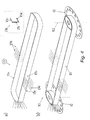
- Fig. 6a the guiding nose (18) that can be attached to the carrier (1x). Such an attachment simplifies the manufacture of the case (1).
- the purpose of this guiding nose (18) is to direct the carrier (1x) in the same linear path during its back and forth traversal and yet make it capable of laying the yarn in two different paths.
- the guiding nose (18) is essentially a bar that has tapered ends.
- the novel feature of this guiding nose (18) is that its tips (18a and 18b) are offset or displaced oppositely about the central axis (18c) as shown in the figure.
- the tips (18a and 18b) do not lie in the same straight line as happens with the tips of a conventional shuttle.
- Fig. 6b shows a three-dimensional view of the guiding nose (18). In Fig.
- 6c is shown the relative arrangement of the guiding nose (18) and the carrier (1x).
- the assembly of the carrier (1x) and the guiding nose (18) may now be referred to as the self-guiding carrier (1y) . It may be restated here that the offset or displaced tips (18a, 18b) could also be directly built into the case (1) without resorting to the use of bar (18), as will become known later.
- the guiding nose (18) is fixed at the rear side of the carrier (1x). By such a placing, the two tips (18a and 18b) do not occur along the central axis (8) of the case (1) indicated in Fig. 2 .
- the two tips (18a and 18b) of the guiding nose (18) are thus offset in two senses about the axis (8) of the case (1), as the two axes (8 and 18c) of the case (1) and the guiding nose (18) respectively are not coincident.
- the guiding nose (18) is located at the rear side of case (1) to keep it close to the plane of shedding/axial yarn support so that the distance between the layers of warp/axial yarns can be kept low. As a consequence, the tension in warp/axial yarns can be kept low besides savings in space can be achieved.
- Fig. 7 the back and forth linear traversal of the self-guiding carrier (1y) in the upper and lower sheds in the 3D-weaving process is illustrated, and Fig. 8 refers to its back and forth linear traversal over and under a layer of axial yarns in the uniaxial noobing process.
- the traversals indicated in Figs. 7 and 8 refer to one cycle of horizontal traversal. In practice horizontal and vertical traversal cycles will be carried out alternately. Thus one cycle of the process will include the carrier's (1y) back and forth traversals in the horizontal and vertical directions.
- Fig. 7a is shown an open shed with the white warp ends at its level position and the grey warp ends raised up.
- the axis of the carrier (1y) occurs in a straight line with the level position of the warp.
- the carrier with the attached guiding nose, and located at the right side of the warp is about to enter into the formed upper shed.
- Fig. 7b is shown the carrier moving in its forward direction.
- the tip of the guiding nose which is above the level position of the warp, directs the carrier into the formed upper shed.
- the carrier deflects the warp yarns laterally by a small distance that is no more than the distance that is just required for the carrier to pass through unhindered.
- FIG. 7c shows the carrier traversing through the shed.
- Fig. 7d is shown the carrier emerging from the shed.
- Fig. 7e shows the carrier on the left side of the levelled warp ends and the laid-in weft interlacing with the warp yarns.
- Fig. 7f the lower shed is formed with the white warp ends remaining at its level position and grey warp ends displaced downwards.
- the carrier is about to enter into the formed lower shed in reference to its level position.
- Fig. 7g is shown the carrier moving in its forward direction. The tip of the guiding nose, which is now below the level position of the warp, directs the carrier into the formed lower shed.
- Fig. 7h shows the carrier traversing through the shed.
- Fig. 7i is shown the carrier emerging from the shed.
- Fig. 7j shows the carrier on the right side of the levelled warp ends and the laid-in weft interlacing with the warp yarns.
- the carrier (1y) moves in the same linear path back and forth, the special construction of its guiding nose (18) directs the carrier (1y) to guide itself in the upper and lower sheds.
- the shed opening does not have to be more than what is just necessary because the carrier (1y) itself deflects the warp yarns laterally by the minimum distance required.
- the warp yarns immediately revert to their assigned positions. They do not have to be maintained highly separated until the carrier (1y) has completely emerged out of the shed.
- the weft which has been shown to be discontinuous, will in practice be a continuous length.
- Fig. 8a shows the axial yarns and the axis of the carrier (1y) occurring in a straight line which is referred to as the level position.
- the axial yarns remain at the level position all through.
- the carrier (1y) at the start of the process cycle is located at the right side of a row of axial yarns and is about to move forward.
- Fig. 8b is shown the carrier moving in its forward direction from right to left side of the row of axial yarns.
- Fig. 8c shows the carrier traversing above the row of axial yarns.
- Fig. 8d is shown the carrier emerging from over the row of axial yarns.
- Fig. 8e shows the carrier on the left side of the row of axial yarns that remain at level position and the laid binding yarn lying straight and over the row of axial yarns.
- the carrier is moving in its forward direction from left to right side of the row of axial yarns.
- Fig. 8g shows the carrier traversing below the row of axial yarns.
- Fig. 8h is shown the carrier emerging from below the row of axial yarns.
- Fig. 8i shows the carrier on the right side of the row of axial yarns that remain at the level position and the laid binding yarn lying straight and below the row of axial yarns.
- the cartridge case parts (1a and 1d) are provided with openings (6a - 6d) on its back walls (1b and 1e). It was also mentioned that the openings (6c and 6d) in the bottom case (1d) were employable to accommodate wheel (10).
- the location of the wheel assembly (12) in the case part (1d) was shown in Fig. 3d . As can be seen in that figure, a part of the flange (10b) of the wheel assembly (12) protrudes out from the wall (1e) through each of the openings (6c and 6d).
- the purpose of having the flange (10b) protruding out of the cartridge case (1) is to be able to turn the wheel (12) by an external driver.
- Such a driving of either of the two wheels (12) is essential to wind yarn (45) into the cartridge (after the carrier (1x) has exhausted the contained yarn) and to take-up the slackness in the yarn (45) (after the carrier (1x) has traversed from one side to the opposite).
- the guiding nose (18) is fixed to the back walls (1b and 1e) of the case parts (1a and 1d) respectively, the guiding nose (18) is also provided with openings (18d and 18e) as indicated in Fig. 6 .
- openings (18d and 18e) As can be inferred from Fig.
- an external driver (40) in the form of either a driving wheel or belt could make contact with the protruding part of the wheel flange (10b) of either of the two assembled wheels (12) to turn it, and hence move the flanged belt (15), when required.
- a suitable electric motor (20) can be installed in the opening (3a and 3b) of the case parts (1a and 1d) as shown in Fig. 9b .
- a driving wheel (21) having teeth that can mesh with the perforations (10c) of the wheel (12) can be attached to the motor (20).
- the motor (20) can be energised through suitable electrical contacts located on the cartridge case (1). Such an electrical contact can be had either continuously during the traversal of the carrier (1y) (e.g. through the guiding nose (18), as one end of it can be had in contact with an electrical source) or intermittently (e.g. when the carrier (1y) has docked into its housing after its traversal).
- the employed multiple carriers (1y) have to be traversed under positive control. This is necessary to manage reliably the large number of the carriers (1y) that will be involved in the process and also to avoid any mishap that might arise under the influence of gravity, especially with the carriers (1y) of the vertical set.
- the reliable traversal of multiple carriers in a given direction gains even more importance when two or more carriers are to be traversed in the same path, either in the same direction or opposite, such as during the production of cross-sectional profiles like H, E, B etc. in separate parts.
- the guiding nose (18) could be used for the positive traversal of the yarn supply source (1x).
- the rear side of the guiding nose (18) could have either teeth or perforations so that it could function as a rack that could be engaged with a pinion or a suitable wheel for moving.
- a profiled groove, such as 'T' for guiding it on matching tracks so that the carrier (1y) can move in a linear guided path and does not come off from the support during traversal.
- the guiding nose (18) could be of a material that can adhere magnetically to an electromagnet attached to, for example, a telescopic arm that can traverse the yarn carrier (1y) from one side of the warp to the opposite.
- the guiding nose (18) could have a suitable profile, for example, it could be of H cross-section or even a box beam.
- the rib of the H profiled beam could be used for holding mechanically the carrier (1y) during transportation.
- the mechanical gripping could be done even pneumatically.
- Another possibility could be that of having either a mechanical or an electromechanical arrangement within the guiding nose (18) that can be engaged with and disengaged from, for example, the carrier driving arm.
- a motor can be installed to drive the carrier (1y).
- a guiding nose (18) could also be suitably extended to transport conventional yarn spools that have one axis of rotation, Y.
- a carrier (22a) comprising case (24a) containing such a spool (23). It could also be attached to a case (24b) to have carrier (22b) that holds more than one such spool (23) as shown in Fig. 10b .
- the guiding nose (18) could be made broader and modified so that it becomes a case (24c) by itself to be a carrier (22c) to contain the spool/s (23) and its driving motor within itself as exemplified in Fig. 10c .
- the axis (Y) of the spool/s (23) will occur perpendicular to the longitudinal axis of the carrier.
- its axis Y will occur parallel to the longitudinal axis of the carrier (22d).
- the two sets of weft/binding yarn carriers are required to be moved alternately in a mutually perpendicular direction, either each or some of these carriers (1y) of the two sets could be equipped with a special form of dent for carrying out the beating-up operation.
- the set of weft/binding yarns that has been laid by the carriers (1y) of one set could be subsequently beaten-up by the dent carrying carriers (1y) of the other set. This way the picking and beating-up operations could be combined in one step and thereby render the 3D textile forming processes efficient.
- a basic form of the dent (27) is indicated in Fig. 11a .
- the shown dent (27) is essentially formed from a wire that may not necessarily have the circular cross-section. It has three characteristic sections: the fixing section (27a), the guiding and weft/binding yarn displacing section (27b), and the packing section (27c).
- the fixing section (27a) is intended for attaching the dent (27) to the carrier (1y).
- the attachment could be done in a variety of ways, both fixed and movable, such as welding, screwing (when the ends are threaded), gripping (through suitable construction of the carrier (1y)), guided in a sleeve under spring pressure etc.
- the fixing section could also be made flexible, e.g. by hinging, so that the dent (27) can bend a little to align automatically with the angle of the disposed converging warp/axial yarns through which it is required to pass.
- the second section (27b) are two in number and occurs at an angle relative to the packing section (27c) of the dent (27). It is intended to guide the whole dent (27) through the shed/adjacent layers of warp/axial yarns progressively without hindrance and also at the same time progressively displace the weft/binding yarns of the other set, that have been laid previously, towards the plane of fabric-fell.
- the two units of the second section (27b), which are similar, will not be functioning simultaneously but one at a time depending on the traversal direction of the carrier (1y).
- the unit (27b) that is on the leading side of the carrier (1y) will be the working unit.
- the packing section (27c) is intended to align or firm up the previously laid weft/binding yarns at the plane of fabric-fell with or without the spring action of the wire. Although this section (27c) has been indicated to be flat, it could be also had in forms like 'V' and 'U'.
- the second and third sections (27b and 27c) of dent (27) could be combined so that the new dent would be one curved section.
- Fig. 11b is shown the location of dent (27) relative to the carrier (1x) .
- the assembly of the beating-up dent (27) and the carrier (1x) may now be referred to as the beating-up carrier (1z).
- the dent (27) could be modified to be relatively stiffer and more stable as exemplified by dent (28) in Fig. 11c . Further, it could be either bent at its fixing section so as to correspond with the angle of the warp/axial yarn layer when disposed in a converging configuration or it could be suitably hinged so that it could align automatically with the disposed angle of the converging warp/axial yarns.
- a construction of the modified dent (28) is exemplified in Fig. 11c .
- the modified dent (28) differs from the previous dent (27) essentially in that it is made from blanked sheet material instead of a wire and with suitable reinforcing members (28f) to impart stiffness and stability.
- the exemplified dent (28) too has the three characteristic sections: (28a) for attaching it to the carrier (1x), (28b) for guiding it through the warp/axial yarn layer and deflecting the weft/binding yarns, and (28c) for packing the weft/binding yarns at the plane of fabric-fell.
- An opening (28e) provides space for the yarn that emerges through the opening (7) of the carrier (1x) .
- using a combination of wire and sheet material could also produce the dent.
- the fixing section and the guiding and weft/binding yarn-displacing section could be made from sheet material and the packing section from a wire.
- the dent can be coated with a suitable material like PTFE.
- FIG. 12 An assembly of the yarn carrier (1x) carrying yarn (45), guiding nose (18) and the dent (27) is illustrated in Fig. 12 to indicate their relative locations. Such an assembly may now be referred to as the yarn supplying cum beating-up means (90).
- Fig. 13a is shown the relative arrangement of the warp/axial yarns (25) and its support plate (25a), the vertical set of carriers (90v) located at the top side of the warp/axial yarns (25), the horizontal set of carriers (90h) located at the left side of the warp/axial yarns (25), the vertical set of weft/binding yarns (45v) and the horizontal set of weft/binding yarns (45h). It may be assumed that the vertical set of weft/binding yarns (45v) have just been laid through the warp/axial yarns (25) and the horizontal set of weft/binding yarns (45h) are now to be laid in a given process cycle. Accordingly, the horizontal set of carriers (90h) will be required to move from the left to the right side of the warp/axial yarns (25).
- Figs. 13b - 13f are shown simplified sequential views from the top of warp to indicate clearly the method of simultaneous picking and beating-up operations relating to the horizontal carriers (90h).
- Fig. 13b shows the carriers (90h) about to enter the warp/axial yarns (25).
- Fig. 13c shows dents (27) entering into the warp/axial yarns (25) and the previously laid set of vertical weft/binding yarns (45v) being pushed toward the plane of fabric-fell (29) by dents (27) as the carriers (90h) traverses in its forward direction.
- Fig. 13d shows dents (27) commencing the beating-up of the set of vertical weft/binding yarns (45v) at the plane of fabric-fell (29).
- Fig. 13b shows the carriers (90h) about to enter the warp/axial yarns (25).
- Fig. 13c shows dents (27) entering into the warp/axial yarns (25) and the previously laid set of vertical weft/bind
- FIG. 13e shows the carriers (90h) beginning to emerge from the warp /axial yarns (25) and the dents (27) completing the beating-up of yarns (45v) at the plane of fabric-fell (29).
- Fig. 13f shows the fully emerged carriers (90h) and the yarns (45v) aligned at the plane of fabric-fell (29).
- the carriers (90h) are traversing through the warp/axial yarns (25), horizontal weft/binding yarns (45h) are also being laid.
- Fig. 14a shows the relative arrangement of the warp/axial yarns (25) and its support plate (25a), the vertical set of carriers (90v) located at the top side of the warp/axial yarns (25), the horizontal set of carriers (90h) located at the right side of the warp/axial yarns (25), the vertical set of weft/binding yarns (45v), the horizontal set of weft/binding yarns (45h).
- the vertical set of carriers (90v) is moved from the topside to the bottom side of the warp/axial yarns (25).
- Figs. 14b - 14f are shown simplified sequential views from the side of warp to indicate clearly the method of simultaneous picking and beating-up operations relating to the vertical carriers (90v).
- Fig. 14b shows the carriers (90v) about to enter the warp/axial yarns (25).
- Fig. 14c shows dents (27) entering into the warp/axial yarns (25) and the previously laid set of horizontal weft/binding yarns (45h) being pushed toward the plane of fabric-fell (29) by dents (27) as the carriers (90v) traverse downwards.
- Fig. 14d shows dents (27) commencing the beating-up of the set of vertical weft/binding yarns (45h) at the plane of fabric-fell (29).
- Fig. 14e shows the carriers (90v) beginning to emerge from the warp / axial yarns (25) and the dents (27) completing the beating-up of yarns (45h) at the plane of fabric-fell (29).
- Fig. 14f shows the fully emerged carriers (90v) and the set of yarns (45h) aligned at the plane of fabric-fell (29).
- the carriers (90v) are traversing through the warp/axial yarns (25), vertical weft/binding yarns (45v) are also being laid.
- the picking and beating-up operations can be carried out simultaneously.
- the set of horizontal carriers (90h) move from one side to the opposite, they beat-up the previously laid set of vertical weft/binding yarns (45v) at the plane of fabric-fell (29) and simultaneously lay the horizontal set of weft/binding yarns (45h) through the warp/axial yarns (25).
- the set of vertical carriers (90v) move from one side to the opposite, they beat-up the previously laid set of horizontal weft/binding yarns (45h) at the plane of fabric-fell (29) and simultaneously lay the vertical set of weft/binding yarns (45v) through the warp/axial yarns (25).
- the carriers (90) could be halted midway, if required, when traversing through the warp/axial yarns (25) and subjected to a forward and backward motion in the direction of the axis (30) by reciprocating the plate (25a) that supports the warp/axial yarns through a suitable working arrangement. This is possible because the carriers (90) are driven under positive control and can be halted at any predetermined point.
- the dent (27/28) could be placed in the carrier under spring pressure and partly emerging from the rear side of the carrier (1x) so that it gets reciprocated when passing over specified raised points on the plate (25a).
- the dent (27/28) could be similarly attached to the head/band (36/37) of the rapier system (39) as shown in Fig. 15 .
- the non-reciprocatory beating-up action would remain as before.
- the indicated rapier head (36) in Fig. 15 could be a means for inserting weft/binding yarn by way of transferring the yarn in the form of either a loop or tip between the warp/axial yarns.
- a knitting needle could also be employed as a rapier that can insert yarn in the form of a loop.
- the rapier head's (36) supporting band (37) could be of either the flexible or rigid type.
- simultaneous beating-up and laying of yarn (45) between the warp/axial yarns (25) could also be achieved by attaching the dent (27/28) to the different types of carriers (22a-22d), which can carry one or more yarn spools (23) of the type having one axis of rotation Y, described earlier in reference to Fig. 10 .
- Fig. 15b is exemplified the dent (28) attached to carrier (22b) indicated earlier to form the carrier (22) for accomplishing simultaneous laying of yarn and beating-up on the lines described in the foregoing.
- beating-up can be useful in those instances of 3D textile production where certain weft/binding yarns of either horizontal or vertical set are not required to be laid but beating-up of the weft/binding yarns of the other set that have been laid should be carried out. For example, in the production of tubular and 'H', 'T' etc. profiled 3D textiles.
- a yarn guide could be installed in the opening (28d) located on the packing section (28c). This way it would become possible to lay the weft/binding yarns closer to the plane of fabric-fell.
- An alternative way to bring the yarn closer to the packing section (27c/28c) would be to have, for example, a tube with suitably located entry and exit ports for conducting the yarn through it instead of employing a dent wire (27).
- either a closed or open channel could be built into it to conduct the yarn (45) to the packing section (28c) from the opening (7) of the carrier (1x).
- the yarn (45) could also be guided to the packing section (27c/28c) of the dents (27/28) by guiding it through suitably located yarn-guides.
- the described yarn supplying means (1x) should not be considered as a weft/binding yarn carrier for 3D-weaving and uniaxial noobing processes only.
- a cartridge (1x) could also find use in textile processes where space requirements may impose restrictions on using large cylindrical packages.
- a carrier (1x) of the described characteristics could be used in braiding process with suitable modifications and in place of bulky creels that feed yarns to certain 2D and 3D textile-forming processes.
- the modified carrier (1x) could be traversed in an upright or standing manner such that its axis (8) occurs perpendicular to its traversal direction.
- the added advantage of using such a yarn carrier (1x) will be the possibility to control the tension of the yarn supplied by suitably energising the installed electric motor (20). Of course in such applications there will be no need to attach the guiding nose (18) to the means (1x).
- yarn used above and which could be handled by the various indicated yarn carriers, should be interpreted broadly, and may e.g. comprise tapes, without deviating from the invention as claimed.
- the tapes so used could be composed of, for example, fibrous material, metallic foils, polymeric material etc.
- the basic construction of the yarn carrier (1x) could be modified to suit a particular application by way of having the yarn about more than two parallel axes of rotation.
- One such construction is exemplified in Fig. 16 wherein the yarn supplying means (50) is shown to have three parallel axes of rotation (X1, X2 and X3).
- the working principle of such a means (50) will be the same as that of the carrier (1x) and needs no further elaboration.
- Such a yarn supplying means (50) could perhaps find application as a, for example, weft measuring, storing and feeding device for use with the shuttleless weaving machines.
- some of the suggested modifications in respect of means (1x) could be as follows:
- a window could be provided at a suitable location on the case part (1a or 1d) to know the yarn material type and amount contained on the flanged belt (15) at any given time.
- This window could also be helpful in accessing the leading tip of the yarn, which enters through the yarn guide, for engaging the yarn to the flanged belt (15) so that it could be latched for winding. Through this window it is also possible to monitor electronically the amount of yarn remaining on the belt (15).
- Another improvement could be to install pins at suitable points inside the carrier (1x) to guide the yarn through the desired path.
- Yet another improvement could be to include an electronic system within the carrier (1x) to indicate whether it is full/empty, running/stopped etc.
- pressure-sensitive pins could be considered for incorporation so that the motor (20) can be activated according to the obtaining needs of the yarn tension.
- spring clips could be used in conjunction with suitable slits on case (1).
- openings on the front walls (1c and 1f) of the carrier (1x) similar to the openings (6a-6d) indicated in Fig. 1 , to drive the wheel (12) from the front side of the carrier to suit a particular situation.
- openings could also be had at the end sides of the yarn cartridge that is of the flat-end type mentioned earlier.
- An opening for receiving the yarn guide could also be provided at one of the end sides of the flat-end type yarn cartridge.
- rolling pins instead of a yarn guide at the opening (7) for according safety to the passing yarn.
Landscapes
- Engineering & Computer Science (AREA)
- Textile Engineering (AREA)
- Looms (AREA)
- Woven Fabrics (AREA)
- Treatment Of Fiber Materials (AREA)
- Treatments For Attaching Organic Compounds To Fibrous Goods (AREA)
- Gloves (AREA)
Claims (39)
- Verfahren zur Herstellung einer Textilie durch 3D-Weben oder uniaxiales Noobing, wobei mindestens ein Garneinführungsmittel (90, 39, 22) zum Legen der Garne (45) durch die Kettfäden / axialen Garne (25) betätigt wird, dadurch gekennzeichnet, dass das Garneinführungsmittel (90, 39, 22) außerdem verwendet wird, um einen Anschlagvorgang auszuführen.
- Verfahren nach Anspruch 1, wobei der Anschlagvorgang und das Legen des Garns im Wesentlichen gleichzeitig ausgeführt werden.
- Verfahren nach Anspruch 1 oder 2, wobei das
Garneinführungsmittel (90, 39, 22) in Richtung der Textildicke und/oder der Textilbreite hindurchgeführt wird. - Verfahren nach Anspruch 3, wobei das Garn sowohl in Richtung der Textildicke als auch in Richtung der Textilbreite gelegt wird und die Garne (45v), die in Richtung der Textildicke gelegt wurden, durch das Betätigen mindestens eines Garneinführungsmittels (90h, 39, 22) in Richtung der Textilbreite angeschlagen werden und die Garne (45h), die in Richtung der Textilbreite gelegt wurden, durch das Betätigen der Garneinführungsmittel (90v, 39, 22) in Richtung der Textildicke angeschlagen werden.
- Verfahren nach einem der vorhergehenden Ansprüche, wobei mehr als ein Garneinführungsmittel (90, 39, 22) verwendet wird, wobei jedes Garneinführungsmittel (90, 39, 22) in einer von mindestens zwei Richtungen betätigt wird.
- Verfahren nach Anspruch 5, wobei die Garneinführungsmittel (90, 39, 22) für mindestens eine Richtung in Gruppen von mindestens zwei betätigt werden.
- Verfahren nach einem der vorhergehenden Ansprüche, wobei das Garneinführungsmittel, das verwendet wird, ein Garnträger (90, 22) ist.
- Verfahren nach einem der vorhergehenden Ansprüche, wobei das verwendete Garneinführungsmittel ein Greifersystem (39) ist.
- Garneinführungsmittel (90, 39, 22), beispielsweise ein Garnträger oder ein Greifer, zur Verwendung bei der Herstellung von Textilien in einem 3D-Webverfahren oder dem Verfahren uniaxialen Noobings, wobei es im Gebrauch durch Schichten von Kettfäden / axialen Garnen (25) hin- und hergeführt wird, um die Garne (45) dazwischen anzuordnen, dadurch gekennzeichnet, dass es ferner Anschlagbügel (27, 28) umfasst, die sich in Richtung der Fachspitze (29) erstrecken, wenn das Einführungsmittel hindurchgeführt wird, und dass der Bügel mindestens einen geneigten Abschnitt (27b, 28b) umfasst, der an den am weitesten entfernten Abschnitt (27c, 28c) angrenzt.
- Garneinführungsmittel nach Anspruch 9, ferner einen drehbaren Garntrageriemen (15) / eine Spule (23) umfassend, auf welchem/welcher das Garn (45) angeordnet ist.
- Garneinführungsmittel nach Anspruch 10, ferner ein Gehäuse (1, 24) umfassend, welches mindestens einen Teil des Garns bedeckt, das auf dem Garnhalter (15/23) angeordnet ist, und welches vorzugsweise das Garn (45) im Wesentlichen umschließt.
- Garneinführungsmittel nach Anspruch 10 oder 11, wobei der Garnhalter einen Garntrageriemen (15) umfasst, auf welchem das Garn (45) angeordnet ist, wobei der Riemen (15) im Verhältnis zum Träger (90) um mindestens zwei Rotationsachsen (X1 und X2) drehbar ist.
- Garneinführungsmittel nach Anspruch 12, wobei die zwei Achsen (X1 und X2) zueinander feststehend sind.
- Garneinführungsmittel nach Anspruch 12 oder 13, wobei die zwei Achsen (X1 und X2) im Wesentlichen parallel zueinander sind.
- Garneinführungsmittel nach einem der Ansprüche 12 bis 14, ferner mindestens zwei Räder (12) umfassend, die derart angeordnet sind, dass sie sich einzeln um die entsprechende Rotationsachse (X1 oder X2) drehen, wobei der Garntrageriemen (15) auf die Räder (12) montiert ist.
- Garneinführungsmittel nach Anspruch 15, wobei mindestens ein Teil des Rades (12) mit einer Anordnung mit starker Reibung versehen ist, beispielsweise mit einer Perforation, Kerbung, Auskehlung, Verzahnung oder dem Aufbringen eines geeigneten Materials, um den Riemen (15) durch eine nicht rutschende Anordnung anzutreiben.
- Garneinführungsmittel nach einem der Ansprüche 12 bis 16, wobei der Garntrageriemen (15) geflanscht ist, um das seitliche Verrutschen des von ihm getragenen Garns (45) zu verhindern.
- Garneinführungsmittel nach einem der Ansprüche 12 bis 16, wobei der Riemen (15a) Mittel zum Ergreifen des Führungsendes der Garns (45) umfasst, bevorzugt eine Schlitz- oder eine Hakenanordnung.
- Garneinführungsmittel nach einem der Ansprüche 12 bis 18, wobei der Riemen (15a) auf mindestens einer, vorzugsweise auf beiden Seiten, mit einer Anordnung mit starker Reibung ausgestattet, beispielsweise gerippt, perforiert oder mit einem rutschfesten Material beschichtet ist.
- Garneinführungsmittel nach einem der Ansprüche 12 bis 19, ferner ein Gehäuse (1) umfassend, welches mindestens einen Teil des Garns (45) bedeckt, das auf dem Riemen (15) angeordnet ist, und welches vorzugsweise das Garn (45) im Wesentlichen umschließt.
- Garneinführungsmittel nach Anspruch 20, wobei das Gehäuse mindestens eine Öffnung (7) umfasst, die einen Durchgangsweg für das Garn (45) zum Einführen in das oder Ausführen aus dem Gehäuse (1) bildet.
- Garneinführungsmittel nach Anspruch 21 als Unteranspruch zu Anspruch 17, wobei der geflanschte Riemen (15) in seiner Querschnittsform an einer Seite derart offen ist, dass die offene Seite des montierten geflanschten Riemens (15) in mindestens einer seiner Laufpositionen zur Öffnung (7) zeigt.
- Garneinführungsmittel nach einem der Ansprüche 20 bis 22, wobei das Gehäuse (1) zusammen mit dem Riemen (15) eine kassettenartige Einheit bildet, wobei die Einheit im Ganzen austauschbar ist.
- Garneinführungsmittel nach einem der Ansprüche 20 bis 23 als Unteranspruch zu Anspruch 15, wobei die Räder (12), der Riemen (15) und das Garn (45) vom Gehäuse (1) umschlossen sind.
- Garneinführungsmittel nach Anspruch 24, wobei das Gehäuse Öffnungen (6a - 6d) zum teilweisen Freilegen der Räder (12) aufweist, um sie von außerhalb des Gehäuses (1) drehen zu können, um das Garn (45) entweder in das Gehäuse (1) zu ziehen oder es daraus auszulassen.
- Garneinführungsmittel nach einem der Ansprüche 20 bis 25, wobei eine der Längsseiten (1 b, 1 e) des Gehäuses (1) länger als die andere (1 c, 1f) ist, um in Richtung der Breite des Trägers eine Verjüngung zu bilden.
- Garneinführungsmittel nach einem der Ansprüche 20 bis 26, wobei sich das Gehäuse (1) in Richtung seiner Dicke verjüngt (9a - 9d).
- Garneinführungsmittel nach Anspruch 17 und einem der Ansprüche 12 bis 16 und 18 bis 27, ferner eine Antriebseinheit, beispielsweise einen Motor (20), umfassend, um den geflanschten Riemen (15) anzutreiben.
- Garneinführungsmittel nach einem der Ansprüche 12 bis 28, dafür vorgesehen, durch die Schichten von Kettfäden / axialen Garnen (25) hin- und hergeführt zu werden, um das Garn (45) dazwischen anzuordnen.
- Garneinführungsmittel nach einem der Ansprüche 9 bis 29, wobei der Anschlagbügel (27, 28) einen am weitesten entfernten Teil (27c, 28c) umfasst, dessen Rand im Wesentlichen parallel zur Durchführrichtung des Trägers (90, 22) ist.
- Garneinführungsmittel nach einem der Ansprüche 9 bis 30, wobei der Anschlagbügel (27, 28) einen geneigten Abschnitt (27b, 28b) umfasst, der in Durchführrichtung an beide Seiten des am weitesten entfernten Teils (27c, 28c) angrenzt.
- Garneinführungsmittel nach einem der Ansprüche 9 bis 31, wobei der Anschlagbügel (27, 28) mindestens teilweise aus einem länglichen Element aufgebaut ist, wie etwa einem Draht, einem flachen Streifen, einem Rohr, und mit seinen Enden an anderen Teilen des Trägers befestigt ist.
- Garneinführungsmittel nach einem der Ansprüche 9 bis 31, wobei der Anschlagbügel (27, 28) mindestens teilweise aus einem Plattenelement aufgebaut ist, wie etwa einem gestanzten Blech.
- Garneinführungsmittel nach einem der Ansprüche 9 bis 33, wobei die Anschlagmittel (27, 28) ferner Garnführungsmittel zum Führen des Garns (45) umfassen, das aus den Garneinführungsmitteln läuft, um an der Fachspitze (29) angeordnet zu werden.
- Garneinführungsmittel nach Anspruch 34, wobei das Garnführungsmittel (28d) in der Nähe des am weitesten entfernten Teils (27c, 28c) des Anschlagbügels (27, 28) angeordnet ist.
- Garneinführungsmittel nach einem der Ansprüche 9 bis 35, wobei die Anschlagbügel (27, 28) im Verhältnis zum Rest des Trägers flexibel angeordnet sind.
- Garneinführungsmittel nach einem der Ansprüche 9 bis 36, wobei es sich um einen Träger handelt, der in Durchführrichtung länglich ist, und sich beide Endabschnitte des Trägers in Durchführrichtung verjüngen und in Spitzen (18a - 18b) enden, die im Verhältnis zur Durchführbahn des Trägers gegeneinander versetzt angeordnet sind, um den Träger (90, 22) selbstführend zu machen, um das Garn (45) im Verhältnis zu einer Schicht der Kettfäden / axialen Garne (25) in zwei verschiedenen Bahnen zu legen, während der Träger (90, 22) hin- und hergeführt wird.
- Garnträger nach Anspruch 37, wobei er mit Mitteln versehen ist, um ihn mit Positive-Control-Steuerung zu betätigen, beispielsweise indem er mit Zähnen, Perforationen, Vorsprüngen, Profilrillen versehen ist oder aus magnetischem Material besteht.
- Garnträger nach Anspruch 38, wobei der Träger eine Antriebseinheit umfasst, die ihn zu einem selbstgetriebenen Träger macht.
Applications Claiming Priority (3)
| Application Number | Priority Date | Filing Date | Title |
|---|---|---|---|
| SE0000721 | 2000-03-06 | ||
| SE0000721A SE520492C2 (sv) | 2000-03-06 | 2000-03-06 | Förfarande och anordning för textiltillverkning |
| PCT/SE2001/000476 WO2001066840A2 (en) | 2000-03-06 | 2001-03-06 | A method and means for textile manufacture |
Publications (2)
| Publication Number | Publication Date |
|---|---|
| EP1305458A2 EP1305458A2 (de) | 2003-05-02 |
| EP1305458B1 true EP1305458B1 (de) | 2010-09-01 |
Family
ID=20278693
Family Applications (1)
| Application Number | Title | Priority Date | Filing Date |
|---|---|---|---|
| EP01910309A Expired - Lifetime EP1305458B1 (de) | 2000-03-06 | 2001-03-06 | Verfahren und mittel zur herstellung von textilien |
Country Status (11)
| Country | Link |
|---|---|
| US (1) | US6889720B2 (de) |
| EP (1) | EP1305458B1 (de) |
| JP (1) | JP5348816B2 (de) |
| KR (1) | KR100786915B1 (de) |
| CN (1) | CN1272228C (de) |
| AT (1) | ATE479787T1 (de) |
| AU (1) | AU2001237880A1 (de) |
| CA (1) | CA2402411C (de) |
| DE (1) | DE60142972D1 (de) |
| SE (1) | SE520492C2 (de) |
| WO (1) | WO2001066840A2 (de) |
Families Citing this family (12)
| Publication number | Priority date | Publication date | Assignee | Title |
|---|---|---|---|---|
| JP4412543B2 (ja) * | 2004-09-21 | 2010-02-10 | 弘治 大石橋 | 帯状繊維束織物の製織装置と製織方法 |
| WO2006075962A1 (en) * | 2005-01-17 | 2006-07-20 | Tape Weaving Sweden Ab | A woven material comprising tape-like warp an dweft, and an apparatus and method for weaving thereof |
| CA2594350C (en) * | 2005-01-17 | 2013-11-19 | Tape Weaving Sweden Ab | Method and apparatus for weaving tape-like warp and weft and material thereof |
| EP2444535B1 (de) * | 2010-10-19 | 2013-09-04 | Tape Weaving Sweden AB | Verfahren und Mittel zur kontrollierten Steuerung von bandartigem Kettfaden für Fachbildungs- und Aufwickelvorgänge |
| CN102021718B (zh) * | 2010-12-21 | 2012-05-30 | 北京光华纺织集团有限公司 | 一种用于重磅织带机的锁边装置 |
| EP2743223B1 (de) * | 2012-12-17 | 2015-01-28 | SSM Schärer Schweiter Mettler AG | Fadenführereinheit für eine Textilmaschine |
| CN103266415B (zh) * | 2013-06-03 | 2014-12-03 | 刘念 | 分体式携纱器 |
| IN2013MU03083A (de) | 2013-09-27 | 2015-07-17 | Sharad Narhar Kale Mr | |
| TWI650456B (zh) * | 2016-01-28 | 2019-02-11 | 耐克創新有限合夥公司 | 多梭子分區編織系統、方法及材料 |
| CN106498614A (zh) * | 2016-12-22 | 2017-03-15 | 绍兴县通用提花机械有限公司 | 一种新型双福麻布编织机的送纱装置 |
| CN107475877B (zh) * | 2017-09-14 | 2020-05-12 | 东华大学 | 一种用于束状长丝织造的异形梭子 |
| US11339534B2 (en) | 2019-09-18 | 2022-05-24 | Huyck Licensco Inc. | Multi-layer warp bound papermaker's forming fabrics |
Family Cites Families (15)
| Publication number | Priority date | Publication date | Assignee | Title |
|---|---|---|---|---|
| US1038048A (en) * | 1912-02-20 | 1912-09-10 | Adolph Widmer | Shuttle for looms. |
| US3955602A (en) * | 1967-10-16 | 1976-05-11 | Avco Corporation | Apparatus for fabricating three-dimensional fabric material |
| ES353511A1 (es) * | 1968-04-25 | 1969-09-01 | Balaguer Golobart | Dispositivo insertador y posicionador del hilo de trama conel correspondiente apretado del mismo. |
| FR2132560B1 (de) * | 1971-04-05 | 1973-11-23 | Diederichs Sa Ateliers | |
| US4038440A (en) * | 1972-01-24 | 1977-07-26 | Avco Corporation | Three dimensional fabric material |
| SU906639A1 (ru) | 1978-12-27 | 1982-02-23 | Всесоюзный научно-исследовательский институт метизной промышленности | Устройство дл намотки проволоки в пучок |
| SU927827A1 (ru) | 1979-12-17 | 1982-05-15 | Казанский инженерно-строительный институт | Полимерна пленочна композици |
| SU925827A2 (ru) * | 1980-10-01 | 1982-05-07 | Предприятие П/Я А-3159 | Устройство дл намотки гибкого элемента |
| US5076330A (en) * | 1988-09-29 | 1991-12-31 | Three-D Composites Research Corporation | Three-dimensional multi-axis fabric composite materials and methods and apparatuses for making the same |
| JPH03220343A (ja) * | 1990-01-23 | 1991-09-27 | Ishikawa Pref Gov Benchiyaa Bijinesu Kyodo Kumiai | 三次元多軸織物構造体と、それを製織する織機 |
| JPH042840A (ja) * | 1990-04-20 | 1992-01-07 | Toyota Autom Loom Works Ltd | 三次元織物の緯糸挿入方法 |
| JPH0672340B2 (ja) * | 1990-05-09 | 1994-09-14 | 株式会社スリーデイコンポリサーチ | ロッド方式三次元多軸織機の織物ガイド方法及び装置 |
| US5394906A (en) * | 1993-02-10 | 1995-03-07 | The United States Of America As Represented By The Administrator Of The National Aeronautics And Space Administration | Method and apparatus for weaving curved material preforms |
| KR0172096B1 (ko) * | 1996-08-21 | 1999-02-18 | 이동원 | 직기용 위사 안내장치 |
| JPH10325050A (ja) * | 1997-05-22 | 1998-12-08 | Murata Mach Ltd | 三次元織機 |
-
2000
- 2000-03-06 SE SE0000721A patent/SE520492C2/sv unknown
-
2001
- 2001-03-06 AU AU2001237880A patent/AU2001237880A1/en not_active Abandoned
- 2001-03-06 KR KR1020027011629A patent/KR100786915B1/ko not_active Expired - Fee Related
- 2001-03-06 CA CA002402411A patent/CA2402411C/en not_active Expired - Fee Related
- 2001-03-06 CN CNB018062210A patent/CN1272228C/zh not_active Expired - Fee Related
- 2001-03-06 WO PCT/SE2001/000476 patent/WO2001066840A2/en not_active Ceased
- 2001-03-06 JP JP2001565440A patent/JP5348816B2/ja not_active Expired - Fee Related
- 2001-03-06 AT AT01910309T patent/ATE479787T1/de not_active IP Right Cessation
- 2001-03-06 EP EP01910309A patent/EP1305458B1/de not_active Expired - Lifetime
- 2001-03-06 US US10/220,811 patent/US6889720B2/en not_active Expired - Lifetime
- 2001-03-06 DE DE60142972T patent/DE60142972D1/de not_active Expired - Lifetime
Also Published As
| Publication number | Publication date |
|---|---|
| CA2402411C (en) | 2009-12-15 |
| KR100786915B1 (ko) | 2007-12-17 |
| US6889720B2 (en) | 2005-05-10 |
| EP1305458A2 (de) | 2003-05-02 |
| WO2001066840A3 (en) | 2002-01-03 |
| CN1272228C (zh) | 2006-08-30 |
| SE0000721D0 (sv) | 2000-03-06 |
| WO2001066840A2 (en) | 2001-09-13 |
| SE0000721L (sv) | 2001-09-07 |
| CA2402411A1 (en) | 2001-09-13 |
| JP2003526024A (ja) | 2003-09-02 |
| JP5348816B2 (ja) | 2013-11-20 |
| DE60142972D1 (de) | 2010-10-14 |
| US20030116218A1 (en) | 2003-06-26 |
| AU2001237880A1 (en) | 2001-09-17 |
| CN1440361A (zh) | 2003-09-03 |
| KR20020081399A (ko) | 2002-10-26 |
| ATE479787T1 (de) | 2010-09-15 |
| SE520492C2 (sv) | 2003-07-15 |
Similar Documents
| Publication | Publication Date | Title |
|---|---|---|
| EP1305458B1 (de) | Verfahren und mittel zur herstellung von textilien | |
| US3674057A (en) | Method and apparatus for preparing filling in shuttleless loom | |
| EP2721204B1 (de) | Fadenspeichervorrichtung für eine textilmaschine | |
| CN101200839B (zh) | 多轴向经编机 | |
| RU2591772C1 (ru) | Устройство для промежуточного хранения лентообразного уточного материала для ткацкого станка и ткацкий станок с таким устройством | |
| EP0292044B1 (de) | Webverfahren und Webmaschine, die dieses Verfahren anwendet | |
| US7178558B2 (en) | Modular weaving for short production runs | |
| WO2012165231A1 (ja) | 製織機と同製織機による製織方法 | |
| JP4120634B2 (ja) | 糸測長貯留装置 | |
| JPH06615B2 (ja) | 糸の巻取方法および装置 | |
| US7318456B2 (en) | Modular weaving system with individual yarn control | |
| CN112334609B (zh) | 用于纱线加工机的纱线储存装置 | |
| KR200292890Y1 (ko) | 세폭직기의 경사안내용 가이드봉 | |
| WO2020225705A1 (en) | Method for replenishing yarn supplies in a yarn storage device of a textile machine and a yarn storage device provided for this | |
| SU1416547A2 (ru) | Устройство к многозевному ткацкому станку дл намотки уточной нити на шпулю челнока | |
| GB2599675A (en) | Improvements in or relating to yarn storage | |
| JPH07300742A (ja) | 無撚糸織物の製織における緯糸供給方法 | |
| JPH06616B2 (ja) | トラバース装置 | |
| IES72488B2 (en) | A weaving process | |
| JPH06617B2 (ja) | 糸の巻取装置 | |
| IE970021A1 (en) | A weaving process |
Legal Events
| Date | Code | Title | Description |
|---|---|---|---|
| PUAI | Public reference made under article 153(3) epc to a published international application that has entered the european phase |
Free format text: ORIGINAL CODE: 0009012 |
|
| 17P | Request for examination filed |
Effective date: 20020824 |
|
| AK | Designated contracting states |
Designated state(s): AT BE CH CY DE DK ES FI FR GB GR IE IT LI LU MC NL PT SE TR |
|
| AX | Request for extension of the european patent |
Extension state: AL LT LV MK RO SI |
|
| 17Q | First examination report despatched |
Effective date: 20060119 |
|
| GRAP | Despatch of communication of intention to grant a patent |
Free format text: ORIGINAL CODE: EPIDOSNIGR1 |
|
| GRAS | Grant fee paid |
Free format text: ORIGINAL CODE: EPIDOSNIGR3 |
|
| GRAA | (expected) grant |
Free format text: ORIGINAL CODE: 0009210 |
|
| AK | Designated contracting states |
Kind code of ref document: B1 Designated state(s): AT BE CH CY DE DK ES FI FR GB GR IE IT LI LU MC NL PT SE TR |
|
| REG | Reference to a national code |
Ref country code: GB Ref legal event code: FG4D |
|
| REG | Reference to a national code |
Ref country code: CH Ref legal event code: EP |
|
| REG | Reference to a national code |
Ref country code: IE Ref legal event code: FG4D |
|
| REF | Corresponds to: |
Ref document number: 60142972 Country of ref document: DE Date of ref document: 20101014 Kind code of ref document: P |
|
| REG | Reference to a national code |
Ref country code: NL Ref legal event code: VDEP Effective date: 20100901 |
|
| PG25 | Lapsed in a contracting state [announced via postgrant information from national office to epo] |
Ref country code: AT Free format text: LAPSE BECAUSE OF FAILURE TO SUBMIT A TRANSLATION OF THE DESCRIPTION OR TO PAY THE FEE WITHIN THE PRESCRIBED TIME-LIMIT Effective date: 20100901 Ref country code: FI Free format text: LAPSE BECAUSE OF FAILURE TO SUBMIT A TRANSLATION OF THE DESCRIPTION OR TO PAY THE FEE WITHIN THE PRESCRIBED TIME-LIMIT Effective date: 20100901 |
|
| PG25 | Lapsed in a contracting state [announced via postgrant information from national office to epo] |
Ref country code: CY Free format text: LAPSE BECAUSE OF FAILURE TO SUBMIT A TRANSLATION OF THE DESCRIPTION OR TO PAY THE FEE WITHIN THE PRESCRIBED TIME-LIMIT Effective date: 20100901 |
|
| PG25 | Lapsed in a contracting state [announced via postgrant information from national office to epo] |
Ref country code: GR Free format text: LAPSE BECAUSE OF FAILURE TO SUBMIT A TRANSLATION OF THE DESCRIPTION OR TO PAY THE FEE WITHIN THE PRESCRIBED TIME-LIMIT Effective date: 20101202 Ref country code: NL Free format text: LAPSE BECAUSE OF FAILURE TO SUBMIT A TRANSLATION OF THE DESCRIPTION OR TO PAY THE FEE WITHIN THE PRESCRIBED TIME-LIMIT Effective date: 20100901 Ref country code: SE Free format text: LAPSE BECAUSE OF FAILURE TO SUBMIT A TRANSLATION OF THE DESCRIPTION OR TO PAY THE FEE WITHIN THE PRESCRIBED TIME-LIMIT Effective date: 20100901 |
|
| PG25 | Lapsed in a contracting state [announced via postgrant information from national office to epo] |
Ref country code: PT Free format text: LAPSE BECAUSE OF FAILURE TO SUBMIT A TRANSLATION OF THE DESCRIPTION OR TO PAY THE FEE WITHIN THE PRESCRIBED TIME-LIMIT Effective date: 20110103 |
|
| PG25 | Lapsed in a contracting state [announced via postgrant information from national office to epo] |
Ref country code: ES Free format text: LAPSE BECAUSE OF FAILURE TO SUBMIT A TRANSLATION OF THE DESCRIPTION OR TO PAY THE FEE WITHIN THE PRESCRIBED TIME-LIMIT Effective date: 20101212 Ref country code: BE Free format text: LAPSE BECAUSE OF FAILURE TO SUBMIT A TRANSLATION OF THE DESCRIPTION OR TO PAY THE FEE WITHIN THE PRESCRIBED TIME-LIMIT Effective date: 20100901 |
|
| PLBE | No opposition filed within time limit |
Free format text: ORIGINAL CODE: 0009261 |
|
| STAA | Information on the status of an ep patent application or granted ep patent |
Free format text: STATUS: NO OPPOSITION FILED WITHIN TIME LIMIT |
|
| 26N | No opposition filed |
Effective date: 20110606 |
|
| PG25 | Lapsed in a contracting state [announced via postgrant information from national office to epo] |
Ref country code: DK Free format text: LAPSE BECAUSE OF FAILURE TO SUBMIT A TRANSLATION OF THE DESCRIPTION OR TO PAY THE FEE WITHIN THE PRESCRIBED TIME-LIMIT Effective date: 20100901 |
|
| REG | Reference to a national code |
Ref country code: DE Ref legal event code: R097 Ref document number: 60142972 Country of ref document: DE Effective date: 20110606 |
|
| PG25 | Lapsed in a contracting state [announced via postgrant information from national office to epo] |
Ref country code: MC Free format text: LAPSE BECAUSE OF NON-PAYMENT OF DUE FEES Effective date: 20110331 |
|
| REG | Reference to a national code |
Ref country code: CH Ref legal event code: PL |
|
| REG | Reference to a national code |
Ref country code: IE Ref legal event code: MM4A |
|
| PG25 | Lapsed in a contracting state [announced via postgrant information from national office to epo] |
Ref country code: CH Free format text: LAPSE BECAUSE OF NON-PAYMENT OF DUE FEES Effective date: 20110331 Ref country code: LI Free format text: LAPSE BECAUSE OF NON-PAYMENT OF DUE FEES Effective date: 20110331 Ref country code: IE Free format text: LAPSE BECAUSE OF NON-PAYMENT OF DUE FEES Effective date: 20110306 |
|
| PG25 | Lapsed in a contracting state [announced via postgrant information from national office to epo] |
Ref country code: LU Free format text: LAPSE BECAUSE OF NON-PAYMENT OF DUE FEES Effective date: 20110306 |
|
| PG25 | Lapsed in a contracting state [announced via postgrant information from national office to epo] |
Ref country code: TR Free format text: LAPSE BECAUSE OF FAILURE TO SUBMIT A TRANSLATION OF THE DESCRIPTION OR TO PAY THE FEE WITHIN THE PRESCRIBED TIME-LIMIT Effective date: 20100901 |
|
| REG | Reference to a national code |
Ref country code: FR Ref legal event code: PLFP Year of fee payment: 16 |
|
| REG | Reference to a national code |
Ref country code: FR Ref legal event code: PLFP Year of fee payment: 17 |
|
| PGFP | Annual fee paid to national office [announced via postgrant information from national office to epo] |
Ref country code: FR Payment date: 20170322 Year of fee payment: 17 Ref country code: DE Payment date: 20170322 Year of fee payment: 17 |
|
| PGFP | Annual fee paid to national office [announced via postgrant information from national office to epo] |
Ref country code: GB Payment date: 20170322 Year of fee payment: 17 |
|
| PGFP | Annual fee paid to national office [announced via postgrant information from national office to epo] |
Ref country code: IT Payment date: 20170323 Year of fee payment: 17 |
|
| REG | Reference to a national code |
Ref country code: DE Ref legal event code: R119 Ref document number: 60142972 Country of ref document: DE |
|
| GBPC | Gb: european patent ceased through non-payment of renewal fee |
Effective date: 20180306 |
|
| PG25 | Lapsed in a contracting state [announced via postgrant information from national office to epo] |
Ref country code: DE Free format text: LAPSE BECAUSE OF NON-PAYMENT OF DUE FEES Effective date: 20181002 |
|
| PG25 | Lapsed in a contracting state [announced via postgrant information from national office to epo] |
Ref country code: GB Free format text: LAPSE BECAUSE OF NON-PAYMENT OF DUE FEES Effective date: 20180306 Ref country code: IT Free format text: LAPSE BECAUSE OF NON-PAYMENT OF DUE FEES Effective date: 20180306 |
|
| PG25 | Lapsed in a contracting state [announced via postgrant information from national office to epo] |
Ref country code: FR Free format text: LAPSE BECAUSE OF NON-PAYMENT OF DUE FEES Effective date: 20180331 |