EP1303365B1 - Recycled material and mixing machinery - Google Patents
Recycled material and mixing machinery Download PDFInfo
- Publication number
- EP1303365B1 EP1303365B1 EP01947670A EP01947670A EP1303365B1 EP 1303365 B1 EP1303365 B1 EP 1303365B1 EP 01947670 A EP01947670 A EP 01947670A EP 01947670 A EP01947670 A EP 01947670A EP 1303365 B1 EP1303365 B1 EP 1303365B1
- Authority
- EP
- European Patent Office
- Prior art keywords
- spoil
- machine
- site
- lime
- granular
- Prior art date
- Legal status (The legal status is an assumption and is not a legal conclusion. Google has not performed a legal analysis and makes no representation as to the accuracy of the status listed.)
- Expired - Lifetime
Links
- 239000000463 material Substances 0.000 title claims abstract description 95
- 238000002156 mixing Methods 0.000 title claims abstract description 23
- 238000000034 method Methods 0.000 claims abstract description 33
- 230000008569 process Effects 0.000 claims abstract description 31
- 239000000843 powder Substances 0.000 claims abstract description 28
- 235000008733 Citrus aurantifolia Nutrition 0.000 claims abstract description 22
- 235000011941 Tilia x europaea Nutrition 0.000 claims abstract description 22
- 239000008187 granular material Substances 0.000 claims abstract description 22
- 239000004571 lime Substances 0.000 claims abstract description 22
- XLYOFNOQVPJJNP-UHFFFAOYSA-N water Substances O XLYOFNOQVPJJNP-UHFFFAOYSA-N 0.000 claims abstract description 22
- 238000009412 basement excavation Methods 0.000 claims abstract description 16
- 239000004927 clay Substances 0.000 claims abstract description 16
- 239000004568 cement Substances 0.000 claims abstract description 13
- 239000010881 fly ash Substances 0.000 claims abstract description 12
- 239000000203 mixture Substances 0.000 claims abstract description 11
- 238000004064 recycling Methods 0.000 claims description 6
- 238000007599 discharging Methods 0.000 claims description 2
- -1 spoil Substances 0.000 claims description 2
- 239000002689 soil Substances 0.000 abstract description 9
- 239000004615 ingredient Substances 0.000 abstract description 2
- 238000012360 testing method Methods 0.000 description 15
- 238000005303 weighing Methods 0.000 description 11
- 239000007921 spray Substances 0.000 description 6
- 230000032258 transport Effects 0.000 description 5
- 239000004567 concrete Substances 0.000 description 4
- 239000002699 waste material Substances 0.000 description 4
- 238000013461 design Methods 0.000 description 3
- 229910001220 stainless steel Inorganic materials 0.000 description 3
- 239000010935 stainless steel Substances 0.000 description 3
- 230000003068 static effect Effects 0.000 description 3
- 229910001209 Low-carbon steel Inorganic materials 0.000 description 2
- 239000010426 asphalt Substances 0.000 description 2
- 238000010276 construction Methods 0.000 description 2
- 230000001419 dependent effect Effects 0.000 description 2
- 238000011065 in-situ storage Methods 0.000 description 2
- 230000035800 maturation Effects 0.000 description 2
- 238000010248 power generation Methods 0.000 description 2
- 230000001105 regulatory effect Effects 0.000 description 2
- 238000012216 screening Methods 0.000 description 2
- 230000001143 conditioned effect Effects 0.000 description 1
- 230000001276 controlling effect Effects 0.000 description 1
- 230000007613 environmental effect Effects 0.000 description 1
- 238000002474 experimental method Methods 0.000 description 1
- 239000000945 filler Substances 0.000 description 1
- 230000010006 flight Effects 0.000 description 1
- 230000009969 flowable effect Effects 0.000 description 1
- 230000008014 freezing Effects 0.000 description 1
- 238000007710 freezing Methods 0.000 description 1
- 239000012535 impurity Substances 0.000 description 1
- 238000009533 lab test Methods 0.000 description 1
- 208000020442 loss of weight Diseases 0.000 description 1
- 238000010297 mechanical methods and process Methods 0.000 description 1
- 239000005445 natural material Substances 0.000 description 1
- 239000002245 particle Substances 0.000 description 1
- 238000012545 processing Methods 0.000 description 1
- 230000002035 prolonged effect Effects 0.000 description 1
- 230000001681 protective effect Effects 0.000 description 1
- 238000005086 pumping Methods 0.000 description 1
- 238000003908 quality control method Methods 0.000 description 1
- 239000002994 raw material Substances 0.000 description 1
- 230000008439 repair process Effects 0.000 description 1
- 239000004576 sand Substances 0.000 description 1
- 238000002791 soaking Methods 0.000 description 1
- 230000006641 stabilisation Effects 0.000 description 1
- 230000003019 stabilising effect Effects 0.000 description 1
- 239000004575 stone Substances 0.000 description 1
- 238000003860 storage Methods 0.000 description 1
Images


Classifications
-
- E—FIXED CONSTRUCTIONS
- E02—HYDRAULIC ENGINEERING; FOUNDATIONS; SOIL SHIFTING
- E02F—DREDGING; SOIL-SHIFTING
- E02F5/00—Dredgers or soil-shifting machines for special purposes
- E02F5/22—Dredgers or soil-shifting machines for special purposes for making embankments; for back-filling
- E02F5/223—Dredgers or soil-shifting machines for special purposes for making embankments; for back-filling for back-filling
- E02F5/226—Dredgers or soil-shifting machines for special purposes for making embankments; for back-filling for back-filling with means for processing the soil, e.g. screening belts, separators; Padding machines
-
- B—PERFORMING OPERATIONS; TRANSPORTING
- B09—DISPOSAL OF SOLID WASTE; RECLAMATION OF CONTAMINATED SOIL
- B09B—DISPOSAL OF SOLID WASTE NOT OTHERWISE PROVIDED FOR
- B09B3/00—Destroying solid waste or transforming solid waste into something useful or harmless
- B09B3/20—Agglomeration, binding or encapsulation of solid waste
- B09B3/25—Agglomeration, binding or encapsulation of solid waste using mineral binders or matrix
-
- Y—GENERAL TAGGING OF NEW TECHNOLOGICAL DEVELOPMENTS; GENERAL TAGGING OF CROSS-SECTIONAL TECHNOLOGIES SPANNING OVER SEVERAL SECTIONS OF THE IPC; TECHNICAL SUBJECTS COVERED BY FORMER USPC CROSS-REFERENCE ART COLLECTIONS [XRACs] AND DIGESTS
- Y02—TECHNOLOGIES OR APPLICATIONS FOR MITIGATION OR ADAPTATION AGAINST CLIMATE CHANGE
- Y02W—CLIMATE CHANGE MITIGATION TECHNOLOGIES RELATED TO WASTEWATER TREATMENT OR WASTE MANAGEMENT
- Y02W30/00—Technologies for solid waste management
- Y02W30/50—Reuse, recycling or recovery technologies
- Y02W30/91—Use of waste materials as fillers for mortars or concrete
Definitions
- the present invention relates to a process and to a machine for recycling site-won spoil comprising predominantly non-granular cohesive material from an excavation into a material immediately suitable for use as a backfill.
- material is suitable for use as backfill in road work trench excavations.
- the present invention concerns the re-use of site won spoil that is predominantly non-granular cohesive material. This includes clay soils and soils which contain at least 20% clay so that they are cohesive. It is not suitable for use in chalk areas or on rocky ground.
- Performance Requirements of Substitute Aggregate Materials In order to be used in road construction in the United Kingdom the materials used must achieve certain "performance requirements". These requirements include the criteria for the Utilities' Clegg Test and satisfaction of the performance requirements of the Department of Transport as set out in paragraphs 803 and 804 of the Specification for Highway Works 1991. The practice and procedure is further set out in the Code of Practice on the New Roads and Street Works Act 1991 entitled “Specifications for the Reinstatement in Highways” published in June 1992 by the Highways authorities and Utilities Committee (H.A.U.C.). These documents specify the engineering properties required for materials that can be used in certain situations and in particular define Type 1, Type 2 and Type A materials that are needed as the sub-base and backfill of road and pavement structures. For the purposes of this specification references to Type 1, Type 2 or Type A materials mean materials that satisfy the performance requirements for such materials set out in the above documents.
- performance requirements should be construed as referring to relevant performance requirements to be satisfied in order to allow an undertaker of road works to adopt alternative materials.
- CBR Californian Bearing Ratio
- the contractor must also purchase new material to backfill the excavations.
- New material is often derived from crushing and screening quarried stone, sea-dredged materials or land based sand and gravels. If the site of the excavation is distant from suitable sources of such material, the cost of importing relatively small quantities of such material of the required specifications can be expensive. Moreover quarrying has a considerable environmental impact.
- a further technical problem is to provide a machine that can carry out such a process efficiently on site to enable immediate re-use of the material.
- a process has been described in FR-A-2 777 305 (Electricite de France) in which a machine is used to recycle granular material with small amounts of impurities such as clay and silt.
- the machine employs a screening and crushing process and would not be applicable to site won spoil which is predominantly non-granular cohesive material.
- a process for recycling site-won spoil comprising predominantly non-granular cohesive material from an excavation into a material immediately suitable for use as a backfill, comprising the steps of breaking up the extracted spoil then mechanically mixing the broken up extracted spoil with up to 30% added granular material and between 1 and 10% of a powder material comprising lime or lime with the addition of cement and/or pulverised fly ash in an automatically powered machine that continuously rotavates the components together into the output material.
- the powder material may comprise 1-5 % lime or 1-5% lime with the addition of 1-5% cement and/or 1-5% pulverised fly ash.
- pulverised fly ash is used here.
- the material is also referred to as pulverised fuel ash or PFA.
- PFA pulverised fuel ash
- this is material conforming to BS3892 parts 1 and 2 or selected conditioned PFA, which conforms to class 7B of the Specification for Highway Works 600 Series.
- a machine according to claim 8 is proposed. This machine can be set to provide different mix ratios depending on the site conditions in order to deliver a consistent material.
- the machine is mobile so that it can readily be moved from site to site.
- DE-4235355 provides a machine for recycling site-won spoil comprising predominantly non-granular cohesive material from an excavation for immediate re-use as a backfill, comprising means for receiving excavated cohesive material and means for adding a measured amount of powder material
- the machine of the present invention is characterised in that it further comprises means for amalgamating the excavated cohesive material with added granular material, mixing means having at least one mixing screw for mixing the components and discharging them from the machine, water supply means providing a water supply to the mixer and means for controlling the proportions of water, spoil, granular material and powder incorporated into the mix.
- Percentages given in this specification can be read as being by either volume or by weight but all the percentages must be read in the same way.
- the process allows readily available site-won material to be recycled and reduces the landfill requirement by up to 97%. Further it reduces the use of natural resources and no natural material tax is payable. On local or statutory authority projects, use of this process will assist in meeting recycling targets.
- the process is suitable for use in all areas except chalk and can either be carried out on or close to the site, thereby reducing transport costs considerably.
- the process is designed for a predominantly non-granular cohesive material such as one with at least 20% clay. With such material, the process will be effective with the addition of up to 10% powder. In most circumstances the material will be composed of spoil, added granular material and powder material which can be up to 5% lime or lime with the addition of between 1 and 5% cement and/or 1-5% pulverised fly ash.
- the best mix of added granular material and powder material with the spoil can readily be determined using the above guidelines and a knowledge of the clay and moisture content of the spoil.
- the mixing is carried out by any mechanical method such as with the use of mechanical rotavating machinery, mobile mixing machinery or by static mixing plants.
- the spoil could be removed to an off-site location for the process to be carried out.
- the process is also suitable for producing small quantities manually on site.
- the site won material was mixed with 10% granular material in the form of gravel and 3% lime. The mixing was carried out mechanically.
- a laboratory classification test (to BS 1377-2 1990) was carried out showing the material to be cohesive with a plastic index test of 24, confirming the modified material to be non-frost susceptible.
- a further frost test was carried out to BS 812-124 1989 amended as per Specification for Highway Works 1998 Clause 705 and the average heave of the specimen after 96 hours freezing was 4.2mm compared to a maximum allowable heave of 15mm.
- modified material has been used in numerous excavations provided by a utility company and the Clegg tests have ranged between 25-40. This compares favourably with the performance requirement of no less than 18.
- a controlled test was carried out using spoil from a site at The Arches, 24 - 28 Iverson Road, London NW6.
- the moisture content was 24 % which conformed to BS1377 and the clay content was 61%. It was found that a material achieving a Clegg test of 32 and a dynamic core penetrometer CBR test of 38 could be produced using a mixture of spoil with 3% lime, 3% pulverised fly ash and 33% granular material.
- pulverised fly ash in addition to or instead of cement allows the material to be stored for longer periods.
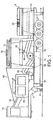
- a machine 2 has been designed to provide effective and consistent implementation of the process. Two embodiments of the machine are shown and it will be appreciated that other layouts are also possible using existing or specially designed components. Like reference numerals are used for similar components in both embodiments.
- the machine of Figures 1 and 2 is described first.
- the machine 2 is mounted on an articulated tri-axle step-frame trailer 4 so that it can be moved to a trenching site.
- Hydraulic jacks, 6 are provided for stabilising the trailer when working on site.
- a hydraulic power pack (not shown) is provided to operate the jacks.
- the machine is designed to move the material from one end to the other of the trailer.
- a hopper 8 provides for the input of site-won spoil and any necessary granular material, which is then passed through a primary rotavator 10.
- a powder silo 12 is mounted downstream of the hopper 8 so as to be able to feed a required measured amount of lime and/or cement and/or pulverised fly ash into a secondary rotavator 14.
- the secondary rotavator also receives spoil fed to it by a weighing feeder from 16 from the output of the primary rotavator 10. From the secondary rotavator 14 the material is fed to a mixer 20 which can be slewed out from the trailer under hydraulic control in order to deposit the material at a suitable location.
- the trailer 4 also supports other equipment necessary for the operation of the machine including a generator 60, diesel tank, water tank 50, electrical cabinet, motor enclosure, access steps and shutter lights for night time operation.
- a generator 60 diesel tank, water tank 50, electrical cabinet, motor enclosure, access steps and shutter lights for night time operation.
- the hopper 8 may be manufactured from 8mm mild steel and is 3000mm long and 1500mm wide at the top.
- the hopper 8 has a removable hopper base which is manufactured from 10mm HARDOX 400. The base is operated by a hydraulic cylinder and valve.
- the hopper 8 has a sloping safety grid 22 at its mouth.
- the safety grid 22 is 3000mm long and 1500mm wide and the spacing within the grid is 200mm by 200mm.
- a water spray bar with stainless steel jets is optionally fitted over the hopper 8. The flow of water can be controlled automatically.
- the hopper 8 contains the primary rotavator or clay pulverisor 10, which breaks up the input material.
- the primary rotavator 10 is located in the bottom of the hopper 8 in order to break up the material into a particle size of the order of 28mm.
- the primary rotavator 10 is 2500mm in length and is powered by a 75kW motor.
- the weighing feed belt 16 extends from the base of the hopper 8 beneath the primary rotavator 10.
- the speed of the weighing feeder belt 16 can be adjusted to control the feed rate.
- the weighing feeder belt 16 is 4300mm long from the centers of its rollers and is 800mm wide. It is fitted with a 4kW motor and suitable gearing.
- the weighing feeder belt 16 provides continuous belt weighing using an electronic load cell, load cell amplifer, 4kW inverter and a speed sensor.
- the weighing feeder belt 16 enables the weight of spoil and granular material being input to the mixer 20 to be continuously monitored.
- the weighing feeder belt 16 delivers the pulverized material to the secondary rotavator 14.
- the secondary rotavator 14 is 700mm in length and is powered by a 15kW motor.
- the powder silo 12 is situated above the secondary rotavator 14. This silo stores lime and/or cement and/or pulverised fly ash which is to be mixed with the pulverized spoil.
- the powder silo 12 is constructed from 4mm mild steel and has an approximate holding volume of 7.5 cubic meters.
- the silo consists of a hopper with support legs 32.
- a screw feeder 30 is located at the bottom of the powder silo 12.
- the powder silo 12 also has a cover and hatch 34.
- a load cell and load cell amplifier are provided in order to monitor the contents of the hopper.
- the screw feeder 30 is 200mm in diameter and 3800mm long and is powered by a 3kW motor with suitable gearing and a 3kW inverter.
- a variable speed metering vane feeder 36 is located at the bottom of the screw feeder 30.
- the variable speed metering vane feeder 36 may be a type BX19, which is fitted with stainless steel vanes and has a flexible outlet shield.
- the variable speed metering vane feeder 36 has a filler pipe with a standard UNICONE (registered trade mark) fitting and a 100mm butterfly valve to close the feeder after filling.
- the variable speed metering vane feeder 36 is fitted with a filter pipe and sock.
- the secondary rotavator 14 has heavy duty replaceable mixing blades, which are 700mm wide. It has a 15kW drive unit. This rotavator 14 mixes the powder through the spoil and granular material.
- the output of the rotavator 14 is delivered to a fixed speed conveyor 40.
- the fixed speed conveyor 40 is a flat chevron belt that is 1800mm long and 800mm wide. It is fitted with a 3kW motor and suitable gearing.
- the fixed speed conveyor 40 delivers the spoil/powder material to the mixer 20.
- the mixer 20 consists of a U-shaped trough containing a single shaft rotating auger type mixer.
- the mixer 20 is 5000mm long and 400mm wide and is fitted with a 7.5kW motor with suitable gearing.
- the mixer 20 has a combination of replaceable mixing blades and auger flights. The rotation of the auger within the mixer 20 causes the spoil and powder material to progress along the mixer 20.
- the mixer 20 is supported on a winch cable 42 which enables it to be raised and lowered. Slewing of the mixer 20 in an horizontal plane is hydraulically controlled.
- the trailer 4 includes a parking crutch 44 to support and locate the mixer 20.
- the parking crutch 44 has suitable lashings to secure the mixer 20 during transit.
- a water spray bar (not shown) is fitted over the inlet of the mixer 20.
- the water flow to the spray bar can be regulated by an operator.
- a control valve and flow-meter are also provided.
- a water tank 50 is fitted to the underside of the trailer 4.
- the approximate dimensions of the water tank 50 are 3500mm in length, 750mm in width and 750mm in height.
- the working capacity of the tank is 1500 litres approximately.
- a protective bumper rail (not shown) can be fitted around the water tank 50 to protect it.
- a power generation unit 60 is mounted on the trailer 4.
- a 200kva generating set is provided to run all the machine functions for the primary rotavator 10, weighing feeder 16, secondary rotavator 14, powder silo 12, conveyor 40, mixer 20 and a water pump.
- a water pump (not shown) is fitted under the power generation unit 60 and is capable of pumping between 40 to 200 litres per minute to the or each water spray at the hopper 8 and mixer 20.
- Controls for the machine are housed in a control cabin 70, which has lockable antivandal shutters.
- the controls include a computer which controls a sequenced starting and stopping of each machine function.
- the computer monitors the material fed on to the feeder 16 and also monitors the feed rate of the powder by loss of weight as monitored by the load cell in the powder silo 12.
- the computer also monitors the total amount of material fed on to the feeder belt 40. Water, if added at the spray at hopper 8 or at the mouth of the mixer 20, will be measured by a flow meter. Rates of feed of raw materials are displayed on a VDU.
- a printer can be used to print data and reports.
- the mixer 20 may be of a design which uses two mixing screws rotating towards each other.
- the mixer may also have several stages with differing screw configurations.
- FIGS 3-5 show an alternative embodiment of the machine. Similar components have similar reference numerals. This design differs in the construction of the mixer.
- a multi-stage mixer is located in the base of the machine which also operates to transport the material towards a discharge end of the machine at which a fold back conveyer 72 can be located.
- a first stage of the mixer 80 is located beneath the hopper 8. This is a twin screw rotavator with a hydraulic drive. The twin screws 82, 84 can be seen in Figure 5. They rotate in opposite senses.
- the first stage 80 passes the spoil to a second stage mixer 86 positioned underneath the powder silo 12.
- An upper part of the housing of the second stage mixer 86 is open to an output from a stainless steel vane feeder 88, which delivers the powder material into the mixer.
- This second stage mixer 86 is also a weighing chamber with load cells. This enables the proportion of powder to spoil and granular material to be controlled.
- the second stage mixer 86 transports its output to a final stage mixer 90, which completes the mixing process and delivers the material to the discharge conveyer 72.
- Other features of the machine are as described in relation to the first embodiment.
- a machine to carry out the mixing and measuring process could be constructed to numerous different designs, only two of which have been described.
- the capacity of the described machine is suitable for processing spoil into a material that can be used as backfill virtually immediately without a prolonged period of maturation.
- the output of the mixer can be directed to a suitable storage area alongside the trench, where it is readily accessible after a few hours maturation, while the piping or other object of the roadworks is installed, for use as backfill to reinstate the sub-base.
- the mobile mixer as described can also be used at a central mixing point away from the excavations.
- the machine can be assembled for static operation at such a site.
Landscapes
- Engineering & Computer Science (AREA)
- Mining & Mineral Resources (AREA)
- Environmental & Geological Engineering (AREA)
- Mechanical Engineering (AREA)
- Civil Engineering (AREA)
- General Engineering & Computer Science (AREA)
- Structural Engineering (AREA)
- Processing Of Solid Wastes (AREA)
- Soil Conditioners And Soil-Stabilizing Materials (AREA)
- Consolidation Of Soil By Introduction Of Solidifying Substances Into Soil (AREA)
- Processing And Handling Of Plastics And Other Materials For Molding In General (AREA)
- Road Paving Structures (AREA)
- Curing Cements, Concrete, And Artificial Stone (AREA)
- Preparation Of Clay, And Manufacture Of Mixtures Containing Clay Or Cement (AREA)
- Separation, Recovery Or Treatment Of Waste Materials Containing Plastics (AREA)
- Agricultural Chemicals And Associated Chemicals (AREA)
- Fertilizers (AREA)
Applications Claiming Priority (7)
| Application Number | Priority Date | Filing Date | Title |
|---|---|---|---|
| GB0017657 | 2000-07-19 | ||
| GB0017657A GB0017657D0 (en) | 2000-07-19 | 2000-07-19 | Recycled aggregates |
| GB0020851A GB0020851D0 (en) | 2000-08-24 | 2000-08-24 | Mixing machine |
| GB0020851 | 2000-08-24 | ||
| GB0101764 | 2001-01-23 | ||
| GB0101764A GB0101764D0 (en) | 2000-07-19 | 2001-01-23 | Recycled aggregates and mixing machine |
| PCT/GB2001/003083 WO2002005978A1 (en) | 2000-07-19 | 2001-07-09 | Recycled material and mixing machinery |
Publications (2)
| Publication Number | Publication Date |
|---|---|
| EP1303365A1 EP1303365A1 (en) | 2003-04-23 |
| EP1303365B1 true EP1303365B1 (en) | 2004-10-06 |
Family
ID=27255811
Family Applications (1)
| Application Number | Title | Priority Date | Filing Date |
|---|---|---|---|
| EP01947670A Expired - Lifetime EP1303365B1 (en) | 2000-07-19 | 2001-07-09 | Recycled material and mixing machinery |
Country Status (20)
| Country | Link |
|---|---|
| US (1) | US6971783B2 (ja) |
| EP (1) | EP1303365B1 (ja) |
| JP (1) | JP2004504518A (ja) |
| CN (1) | CN1221333C (ja) |
| AT (1) | ATE278480T1 (ja) |
| AU (2) | AU2001269316B2 (ja) |
| CA (1) | CA2416668C (ja) |
| DE (1) | DE60106267T2 (ja) |
| DK (1) | DK1303365T3 (ja) |
| ES (1) | ES2228899T3 (ja) |
| GB (1) | GB2380995A (ja) |
| HK (1) | HK1053997A1 (ja) |
| HU (1) | HU224887B1 (ja) |
| MX (1) | MXPA03000524A (ja) |
| NO (1) | NO20030062L (ja) |
| NZ (1) | NZ523529A (ja) |
| PL (1) | PL359463A1 (ja) |
| PT (1) | PT1303365E (ja) |
| WO (1) | WO2002005978A1 (ja) |
| YU (1) | YU1903A (ja) |
Cited By (1)
| Publication number | Priority date | Publication date | Assignee | Title |
|---|---|---|---|---|
| CN110983935A (zh) * | 2019-11-22 | 2020-04-10 | 胡拴紧 | 一种公路废旧沥青剔除再生施工一体装置 |
Families Citing this family (19)
| Publication number | Priority date | Publication date | Assignee | Title |
|---|---|---|---|---|
| US7114842B2 (en) * | 2000-07-05 | 2006-10-03 | W.R. Grace & Co.-Conn. | Controlling ready mixed concrete sludge water |
| GB2379894B (en) | 2001-07-19 | 2003-08-13 | Keanes Ltd | Recycled material mixing machine |
| ITMI20051381A1 (it) * | 2005-07-20 | 2007-01-21 | Ecoassistenza S R L | Dispositivo di sicurezza per un nastro di alimentazione e una pressa destinata alla compressione di rifiuti |
| FR2889096B1 (fr) | 2005-07-29 | 2007-11-02 | Recymo Sarl | Installation de traitement de deblais limoneux d'un chantier et procede de traitement de ces deblais limoneux mettant en oeuvre ladite installation |
| PL208788B1 (pl) * | 2006-03-31 | 2011-06-30 | Przedsiębiorstwo Robot Geol Wiertniczych Grażyna Janik Roman Kuś Społka Jaw | Środek uszczelniający do tworzenia przesłon hydroizolacyjnych |
| US7581903B1 (en) | 2006-06-08 | 2009-09-01 | Thermoforte, Inc. | Method of manufacture and installation flowable thermal backfills |
| US7393133B2 (en) * | 2006-12-05 | 2008-07-01 | Ernesto Acosta | Soil mixer with scalloped cylinder |
| GB0711423D0 (en) * | 2007-06-13 | 2007-07-25 | Jones Graham A | Compact concrete mixer |
| BRPI0820379A2 (pt) | 2007-11-08 | 2015-05-19 | Glaxosmithkline Llc | Sistemas e métodos de dispensação de produto médico |
| US20090301028A1 (en) * | 2008-03-07 | 2009-12-10 | Steven Pfoff | Method for constructing cultured stone block buildings |
| GB2478150A (en) * | 2010-02-26 | 2011-08-31 | Yorkshire Water Services Ltd | A material recycling apparatus for processing trench arisings |
| JP5540286B2 (ja) * | 2010-11-08 | 2014-07-02 | 王子ホールディングス株式会社 | 路盤材およびその製造方法 |
| CN106001067A (zh) * | 2016-06-30 | 2016-10-12 | 熊汉夫 | 前门式双向垃圾进料机械装置及其垃圾处理方法 |
| US10718099B2 (en) * | 2017-12-29 | 2020-07-21 | Farzad Moradi | Leveling, tune-up and compacting device |
| CN108396805A (zh) * | 2018-03-14 | 2018-08-14 | 彭红星 | 一种建筑用地下存储物自动填埋装置 |
| DE102018009470B4 (de) * | 2018-12-03 | 2022-06-09 | Wilhelm Geiger Gmbh & Co. Kg | Verfahren zur aufbereitung eines gemisches |
| CN112192734A (zh) * | 2019-08-08 | 2021-01-08 | 马鞍山市新桥工业设计有限公司 | 一种建筑垃圾处理系统的操作方法 |
| CN112681067B (zh) * | 2021-01-22 | 2022-04-29 | 杭州路顺环境建设有限公司 | 一种沥青混凝土制备方法 |
| CN113152386B (zh) * | 2021-02-04 | 2023-03-21 | 南昌工学院 | 湿法堆存尾矿库缆式起重机分级筑坝系统 |
Family Cites Families (47)
| Publication number | Priority date | Publication date | Assignee | Title |
|---|---|---|---|---|
| SU392030A1 (ru) | 1971-04-14 | 1973-07-27 | Шлакоминёральная смёсь для устройства оснований автомобильных дорог | |
| SU546679A1 (ru) | 1974-08-16 | 1977-02-15 | Государственный Дорожный Научно-Исследовательский Институт | Состав дл возведени оснований |
| JPS5295736A (en) | 1976-02-09 | 1977-08-11 | Yamaso Kk | Special sawdust mortar |
| SU576297A1 (ru) | 1976-05-03 | 1977-10-15 | Государственный Дорожный Научно-Исследовательский Институт | Строительна смесь дл устройства оснований автомобильных дорог |
| US4072435A (en) * | 1976-11-11 | 1978-02-07 | Irl Daffin Associates, Inc. | Method and apparatus for maintaining highways |
| US4071226A (en) * | 1976-11-16 | 1978-01-31 | Miller Charles R | Portable concrete proportioning mixer |
| US4089053A (en) * | 1977-05-16 | 1978-05-09 | Continental Oil Company | Hose and linkage support apparatus for a sump vehicle |
| US4219279A (en) * | 1979-03-26 | 1980-08-26 | Haws Paul M | Mobile gunnite material mixer |
| GB2064931B (en) | 1979-12-13 | 1983-05-18 | Wye Double Digger Co Ltd | Land drainage |
| US4551024A (en) * | 1981-04-24 | 1985-11-05 | Clapp Thomas R | Mixing apparatus for cementitious materials |
| US4406548A (en) * | 1982-04-02 | 1983-09-27 | Haws Paul M | Mobile concrete mixing apparatus |
| US4586824A (en) * | 1982-04-02 | 1986-05-06 | Haws Paul M | Mobile concrete mixing apparatus |
| FR2558862B1 (fr) | 1984-01-26 | 1987-02-13 | Vidal Pierre | Procede de traitement de sol par mise en oeuvre d'un mortier obtenu par broyage et/ou desintegration des materiaux extraits, avec adjonction d'eau et d'un liant |
| US4579459A (en) * | 1984-06-20 | 1986-04-01 | Zimmerman Harold M | Mixing auger mounting and storage arrangement |
| DE3520149A1 (de) | 1985-06-05 | 1986-12-11 | Johannes 3530 Warburg Peine | Verfahren und vorrichtung zum entwaessern von hafenschlamm |
| US4624575A (en) * | 1985-08-30 | 1986-11-25 | Lantz Construction Company | Cement mobile mixer |
| US4712919A (en) * | 1987-01-06 | 1987-12-15 | Bouldin & Lawson, Inc. | Continuous soil mixing apparatus |
| US4768884A (en) * | 1987-03-03 | 1988-09-06 | Elkin Luther V | Cement mixer for fast setting materials |
| US4874283A (en) * | 1988-02-29 | 1989-10-17 | Tilcon Tomasso | Front dispensing truck with vertically and horizontally swingable screw conveyor |
| US4830537A (en) * | 1988-04-19 | 1989-05-16 | Scoralin Inc. | Flexible pipe or cable laying apparatus |
| AT389474B (de) | 1988-05-20 | 1989-12-11 | Riehl Herwirsch Georg Dr | Verwendung von mineralischen, silicatischen/ carbonatischen feinteilen zur geordneten ablagerung von abfallstoffen |
| US4913586A (en) * | 1988-08-15 | 1990-04-03 | Analytical Liquid Waste Systems, Inc. | Mixture for detoxification of contaminated soil |
| JP3229940B2 (ja) * | 1989-11-30 | 2001-11-19 | 三菱レイヨン株式会社 | 連続混練機 |
| JP3080627B2 (ja) * | 1989-12-13 | 2000-08-28 | 三菱レイヨン株式会社 | 連続混練機 |
| US5005980A (en) * | 1990-01-05 | 1991-04-09 | Zimmerman Harold M | Sludge/soil mixing machine |
| GB2258672B (en) | 1991-08-14 | 1995-04-19 | Roxbury Ltd | Improvements in or relating to ground preparation |
| DE4235355C1 (de) * | 1992-10-21 | 1993-12-02 | Suilmann Tiefbau Gmbh & Co Kg | Verfahren zum Verlegen von Rohren, Kabeln oder dgl. |
| US5433520A (en) * | 1993-12-13 | 1995-07-18 | Michigan Ash Sales Company | Method and apparatus for continuously processing particulate cementitious material and fly ash solids and mixing them with a liquid to provide a liquid slurry of consistent proportions |
| DE4409507A1 (de) | 1994-03-19 | 1995-09-21 | Walter Schoelkopf | Vorrichtung zur Aufbereitung von Erdreich zu einem standfesten Baumaterial |
| US5468435A (en) * | 1994-05-09 | 1995-11-21 | Texas Incinerator Co., Tx | Contaminant solidifying and stabilizing apparatus and process |
| JP3172932B2 (ja) | 1994-07-05 | 2001-06-04 | 大成建設株式会社 | 発生土を用いた水硬性組成物の製造方法 |
| JP2717528B2 (ja) * | 1995-12-18 | 1998-02-18 | 月夫 井 | 構造物構築地盤の液状化対策工法 |
| JP3242565B2 (ja) * | 1996-01-12 | 2001-12-25 | 株式会社小松製作所 | 土の解砕混合方法およびその装置 |
| JP2867235B2 (ja) * | 1996-01-12 | 1999-03-08 | 株式会社小松製作所 | 自走式土質改良機 |
| FR2756769B1 (fr) | 1996-12-11 | 1999-02-05 | Eds Equipements De Depollution | Machine mobile pour traiter les terres naturelles des sols pour pouvoir les reutiliser en remblais et pour depolluer les sols pollues |
| RU2117090C1 (ru) | 1997-02-10 | 1998-08-10 | Томская государственная архитектурно-строительная академия | Способ возведения основания дорожной одежды |
| DE69732434T2 (de) | 1997-05-07 | 2006-01-12 | Raffaello Bernabei | Verfahren zur kaltumwandlung von stadtmüll und/oder schlamm in inerten materialien, anlage zur durchführen des verfahrens und so erhaltene produkte |
| FR2777305B1 (fr) | 1998-04-09 | 2000-06-16 | Electricite De France | Procede de traitement de deblais, installation pour sa mise en oeuvre et remblai obtenu |
| JP3387829B2 (ja) | 1998-07-24 | 2003-03-17 | 日立建機株式会社 | 自走式土質改良機械 |
| US6183159B1 (en) * | 1998-07-24 | 2001-02-06 | Hitachi Construction Machinery Co., Ltd. | Automotive soil treating machine |
| US5951751A (en) * | 1998-10-26 | 1999-09-14 | Chemical Lime Company | Flowable fill composition and method |
| JP2000355954A (ja) * | 1999-06-15 | 2000-12-26 | Komatsu Ltd | 自走式土質改良機 |
| JP4176254B2 (ja) * | 1999-09-27 | 2008-11-05 | 株式会社小松製作所 | 土質改良機 |
| GB0009117D0 (en) | 2000-04-13 | 2000-05-31 | Univ Heriot Watt | Process for reusing soil arisings from excavations |
| US6811300B2 (en) * | 2001-03-08 | 2004-11-02 | Komatsu Ltd. | Rotational speed controller for mixing equipment of soil modifying machine and engine speed controller for soil modifying machine |
| GB2379894B (en) * | 2001-07-19 | 2003-08-13 | Keanes Ltd | Recycled material mixing machine |
| JP3772306B2 (ja) * | 2002-07-30 | 2006-05-10 | 株式会社小松製作所 | 土質改良装置 |
-
2001
- 2001-07-09 US US10/333,489 patent/US6971783B2/en not_active Expired - Fee Related
- 2001-07-09 AU AU2001269316A patent/AU2001269316B2/en not_active Ceased
- 2001-07-09 AU AU6931601A patent/AU6931601A/xx active Pending
- 2001-07-09 GB GB0300898A patent/GB2380995A/en not_active Withdrawn
- 2001-07-09 MX MXPA03000524A patent/MXPA03000524A/es unknown
- 2001-07-09 HU HU0303076A patent/HU224887B1/hu not_active IP Right Cessation
- 2001-07-09 WO PCT/GB2001/003083 patent/WO2002005978A1/en active IP Right Grant
- 2001-07-09 YU YU1903A patent/YU1903A/sh unknown
- 2001-07-09 PT PT01947670T patent/PT1303365E/pt unknown
- 2001-07-09 CN CNB01812948XA patent/CN1221333C/zh not_active Expired - Fee Related
- 2001-07-09 NZ NZ523529A patent/NZ523529A/en not_active IP Right Cessation
- 2001-07-09 DE DE60106267T patent/DE60106267T2/de not_active Expired - Lifetime
- 2001-07-09 AT AT01947670T patent/ATE278480T1/de not_active IP Right Cessation
- 2001-07-09 ES ES01947670T patent/ES2228899T3/es not_active Expired - Lifetime
- 2001-07-09 CA CA 2416668 patent/CA2416668C/en not_active Expired - Fee Related
- 2001-07-09 PL PL01359463A patent/PL359463A1/xx unknown
- 2001-07-09 JP JP2002511905A patent/JP2004504518A/ja not_active Withdrawn
- 2001-07-09 EP EP01947670A patent/EP1303365B1/en not_active Expired - Lifetime
- 2001-07-09 DK DK01947670T patent/DK1303365T3/da active
-
2003
- 2003-01-06 NO NO20030062A patent/NO20030062L/no not_active Application Discontinuation
- 2003-09-03 HK HK03106280A patent/HK1053997A1/xx not_active IP Right Cessation
Cited By (2)
| Publication number | Priority date | Publication date | Assignee | Title |
|---|---|---|---|---|
| CN110983935A (zh) * | 2019-11-22 | 2020-04-10 | 胡拴紧 | 一种公路废旧沥青剔除再生施工一体装置 |
| CN110983935B (zh) * | 2019-11-22 | 2021-07-09 | 胡拴紧 | 一种公路废旧沥青剔除再生施工一体装置 |
Also Published As
| Publication number | Publication date |
|---|---|
| PT1303365E (pt) | 2005-01-31 |
| DE60106267D1 (de) | 2004-11-11 |
| US20030164418A1 (en) | 2003-09-04 |
| WO2002005978A1 (en) | 2002-01-24 |
| CA2416668C (en) | 2008-08-05 |
| ATE278480T1 (de) | 2004-10-15 |
| HU224887B1 (en) | 2006-04-28 |
| AU6931601A (en) | 2002-01-30 |
| GB0300898D0 (en) | 2003-02-12 |
| CN1221333C (zh) | 2005-10-05 |
| AU2001269316B2 (en) | 2004-09-23 |
| NO20030062D0 (no) | 2003-01-06 |
| DE60106267T2 (de) | 2006-03-09 |
| JP2004504518A (ja) | 2004-02-12 |
| US6971783B2 (en) | 2005-12-06 |
| CA2416668A1 (en) | 2002-01-24 |
| EP1303365A1 (en) | 2003-04-23 |
| HUP0303076A2 (en) | 2004-01-28 |
| CN1443097A (zh) | 2003-09-17 |
| MXPA03000524A (es) | 2003-05-23 |
| PL359463A1 (en) | 2004-08-23 |
| GB2380995A (en) | 2003-04-23 |
| HK1053997A1 (en) | 2003-11-14 |
| YU1903A (sh) | 2005-06-10 |
| ES2228899T3 (es) | 2005-04-16 |
| DK1303365T3 (da) | 2005-01-10 |
| NZ523529A (en) | 2004-08-27 |
| NO20030062L (no) | 2003-03-07 |
Similar Documents
| Publication | Publication Date | Title |
|---|---|---|
| EP1303365B1 (en) | Recycled material and mixing machinery | |
| AU2001269316A1 (en) | Recycled material and mixing machinery | |
| CA2078564C (en) | Pavement and base recycle method and apparatus | |
| JPH11217822A (ja) | 自走式土質改良機 | |
| KR102122387B1 (ko) | 회전식 파쇄혼합장치를 이용한 개량토의 제조관리시스템 | |
| CN101319483A (zh) | 粉细砂物理改良的路基填筑施工工法 | |
| JP2000073397A (ja) | ミキシングタンクの攪拌装置 | |
| Kaneshiro et al. | Controlled Low Strength Material for Pipeline Backfill— Specifications, Case Histories and Lessons Learned | |
| RU2279324C2 (ru) | Способ повторного использования вынутого на рабочей площадке грунта и установка для его осуществления | |
| CN115518960A (zh) | 一种工程渣土资源化利用厂 | |
| Pierzyna | Liquidation of shafts’ workings with the use of the mobile installation | |
| KR100874754B1 (ko) | 경량혼합재 생산 플랜트 및 경량혼합재를 이용한 연약지반 개량공법 | |
| JPH10225700A (ja) | 建設汚泥の脱水ケーキの混合改良土のリサイクルシステム | |
| JPS601447B2 (ja) | 道路掘削工事における土砂処理方法 | |
| Kennedy et al. | Hydraulically-bound mixtures for pavements | |
| Asthana et al. | Construction Aspects of Dams | |
| US20230250596A1 (en) | Apparatus and method of treating soil | |
| Miki et al. | New soil treatment methods in Japan | |
| KR100440688B1 (ko) | 고화토 파쇄선별혼합장치 및 그 제조방법과 제조된 고화토를 이용한 차수층 시공방법 | |
| Braithwaite et al. | The infilling of limestone mines with rock paste | |
| McDonald et al. | Applications of roller-compacted concrete in rehabilitation and replacement of hydraulic structures | |
| Hoff | A Concept for Rapid Repair of Bomb-Damaged Runways Using Regulated-Set Cement | |
| Rajendran | Controlled low strength materials (CLSM), reported by ACI Committee 229 | |
| JPS601448B2 (ja) | 道路掘削工事における土砂処理方法 | |
| Schrader et al. | Concrete dam construction and foundation treatment |
Legal Events
| Date | Code | Title | Description |
|---|---|---|---|
| PUAI | Public reference made under article 153(3) epc to a published international application that has entered the european phase |
Free format text: ORIGINAL CODE: 0009012 |
|
| 17P | Request for examination filed |
Effective date: 20030219 |
|
| AK | Designated contracting states |
Designated state(s): AT BE CH CY DE DK ES FI FR GB GR IE IT LI LU MC NL PT SE TR |
|
| AX | Request for extension of the european patent |
Extension state: AL LT LV MK RO SI |
|
| 17Q | First examination report despatched |
Effective date: 20031020 |
|
| GRAP | Despatch of communication of intention to grant a patent |
Free format text: ORIGINAL CODE: EPIDOSNIGR1 |
|
| GRAS | Grant fee paid |
Free format text: ORIGINAL CODE: EPIDOSNIGR3 |
|
| GRAA | (expected) grant |
Free format text: ORIGINAL CODE: 0009210 |
|
| AK | Designated contracting states |
Kind code of ref document: B1 Designated state(s): AT BE CH CY DE DK ES FI FR GB GR IE IT LI LU MC NL PT SE TR |
|
| REG | Reference to a national code |
Ref country code: GB Ref legal event code: FG4D |
|
| REG | Reference to a national code |
Ref country code: CH Ref legal event code: EP |
|
| REG | Reference to a national code |
Ref country code: IE Ref legal event code: FG4D |
|
| REF | Corresponds to: |
Ref document number: 60106267 Country of ref document: DE Date of ref document: 20041111 Kind code of ref document: P |
|
| REG | Reference to a national code |
Ref country code: SE Ref legal event code: TRGR |
|
| REG | Reference to a national code |
Ref country code: GR Ref legal event code: EP Ref document number: 20040404343 Country of ref document: GR |
|
| REG | Reference to a national code |
Ref country code: CH Ref legal event code: NV Representative=s name: A. BRAUN, BRAUN, HERITIER, ESCHMANN AG PATENTANWAE Ref country code: PT Ref legal event code: SC4A Effective date: 20041203 |
|
| REG | Reference to a national code |
Ref country code: HK Ref legal event code: GR Ref document number: 1053997 Country of ref document: HK |
|
| LTIE | Lt: invalidation of european patent or patent extension |
Effective date: 20041006 |
|
| REG | Reference to a national code |
Ref country code: ES Ref legal event code: FG2A Ref document number: 2228899 Country of ref document: ES Kind code of ref document: T3 |
|
| PGFP | Annual fee paid to national office [announced via postgrant information from national office to epo] |
Ref country code: TR Payment date: 20050513 Year of fee payment: 5 |
|
| PLBE | No opposition filed within time limit |
Free format text: ORIGINAL CODE: 0009261 |
|
| STAA | Information on the status of an ep patent application or granted ep patent |
Free format text: STATUS: NO OPPOSITION FILED WITHIN TIME LIMIT |
|
| ET | Fr: translation filed | ||
| 26N | No opposition filed |
Effective date: 20050707 |
|
| PGFP | Annual fee paid to national office [announced via postgrant information from national office to epo] |
Ref country code: LU Payment date: 20060704 Year of fee payment: 6 |
|
| PGFP | Annual fee paid to national office [announced via postgrant information from national office to epo] |
Ref country code: GR Payment date: 20060707 Year of fee payment: 6 |
|
| PGFP | Annual fee paid to national office [announced via postgrant information from national office to epo] |
Ref country code: MC Payment date: 20060727 Year of fee payment: 6 |
|
| PG25 | Lapsed in a contracting state [announced via postgrant information from national office to epo] |
Ref country code: MC Free format text: LAPSE BECAUSE OF NON-PAYMENT OF DUE FEES Effective date: 20070731 |
|
| REG | Reference to a national code |
Ref country code: CH Ref legal event code: PFA Owner name: KEANES LIMITED Free format text: KEANES LIMITED#4 IVERSON ROAD#LONDON NW6 2HT (GB) -TRANSFER TO- KEANES LIMITED#4 IVERSON ROAD#LONDON NW6 2HT (GB) |
|
| PGFP | Annual fee paid to national office [announced via postgrant information from national office to epo] |
Ref country code: CH Payment date: 20080709 Year of fee payment: 8 Ref country code: DK Payment date: 20080708 Year of fee payment: 8 Ref country code: PT Payment date: 20080807 Year of fee payment: 8 |
|
| PGFP | Annual fee paid to national office [announced via postgrant information from national office to epo] |
Ref country code: AT Payment date: 20080722 Year of fee payment: 8 Ref country code: FI Payment date: 20080708 Year of fee payment: 8 |
|
| PGFP | Annual fee paid to national office [announced via postgrant information from national office to epo] |
Ref country code: CY Payment date: 20080806 Year of fee payment: 8 |
|
| PG25 | Lapsed in a contracting state [announced via postgrant information from national office to epo] |
Ref country code: GR Free format text: LAPSE BECAUSE OF NON-PAYMENT OF DUE FEES Effective date: 20080206 |
|
| PGFP | Annual fee paid to national office [announced via postgrant information from national office to epo] |
Ref country code: SE Payment date: 20080706 Year of fee payment: 8 |
|
| PG25 | Lapsed in a contracting state [announced via postgrant information from national office to epo] |
Ref country code: LU Free format text: LAPSE BECAUSE OF NON-PAYMENT OF DUE FEES Effective date: 20070709 |
|
| PG25 | Lapsed in a contracting state [announced via postgrant information from national office to epo] |
Ref country code: TR Free format text: LAPSE BECAUSE OF FAILURE TO SUBMIT A TRANSLATION OF THE DESCRIPTION OR TO PAY THE FEE WITHIN THE PRESCRIBED TIME-LIMIT Effective date: 20041006 |
|
| REG | Reference to a national code |
Ref country code: PT Ref legal event code: MM4A Free format text: LAPSE DUE TO NON-PAYMENT OF FEES Effective date: 20100111 |
|
| REG | Reference to a national code |
Ref country code: CH Ref legal event code: PL |
|
| REG | Reference to a national code |
Ref country code: DK Ref legal event code: EBP |
|
| EUG | Se: european patent has lapsed | ||
| PG25 | Lapsed in a contracting state [announced via postgrant information from national office to epo] |
Ref country code: CH Free format text: LAPSE BECAUSE OF NON-PAYMENT OF DUE FEES Effective date: 20090731 Ref country code: PT Free format text: LAPSE BECAUSE OF NON-PAYMENT OF DUE FEES Effective date: 20100111 Ref country code: FI Free format text: LAPSE BECAUSE OF NON-PAYMENT OF DUE FEES Effective date: 20090709 Ref country code: LI Free format text: LAPSE BECAUSE OF NON-PAYMENT OF DUE FEES Effective date: 20090731 |
|
| PG25 | Lapsed in a contracting state [announced via postgrant information from national office to epo] |
Ref country code: CY Free format text: LAPSE BECAUSE OF NON-PAYMENT OF DUE FEES Effective date: 20090709 |
|
| PG25 | Lapsed in a contracting state [announced via postgrant information from national office to epo] |
Ref country code: AT Free format text: LAPSE BECAUSE OF NON-PAYMENT OF DUE FEES Effective date: 20090709 |
|
| PG25 | Lapsed in a contracting state [announced via postgrant information from national office to epo] |
Ref country code: DK Free format text: LAPSE BECAUSE OF NON-PAYMENT OF DUE FEES Effective date: 20090731 |
|
| PG25 | Lapsed in a contracting state [announced via postgrant information from national office to epo] |
Ref country code: SE Free format text: LAPSE BECAUSE OF NON-PAYMENT OF DUE FEES Effective date: 20090710 |
|
| PGFP | Annual fee paid to national office [announced via postgrant information from national office to epo] |
Ref country code: NL Payment date: 20130730 Year of fee payment: 13 Ref country code: ES Payment date: 20130731 Year of fee payment: 13 |
|
| PGFP | Annual fee paid to national office [announced via postgrant information from national office to epo] |
Ref country code: IT Payment date: 20130731 Year of fee payment: 13 |
|
| PGFP | Annual fee paid to national office [announced via postgrant information from national office to epo] |
Ref country code: BE Payment date: 20130830 Year of fee payment: 13 |
|
| REG | Reference to a national code |
Ref country code: NL Ref legal event code: V1 Effective date: 20150201 |
|
| PG25 | Lapsed in a contracting state [announced via postgrant information from national office to epo] |
Ref country code: NL Free format text: LAPSE BECAUSE OF NON-PAYMENT OF DUE FEES Effective date: 20150201 |
|
| PG25 | Lapsed in a contracting state [announced via postgrant information from national office to epo] |
Ref country code: IT Free format text: LAPSE BECAUSE OF NON-PAYMENT OF DUE FEES Effective date: 20140709 |
|
| REG | Reference to a national code |
Ref country code: FR Ref legal event code: PLFP Year of fee payment: 15 |
|
| REG | Reference to a national code |
Ref country code: ES Ref legal event code: FD2A Effective date: 20150826 |
|
| PG25 | Lapsed in a contracting state [announced via postgrant information from national office to epo] |
Ref country code: ES Free format text: LAPSE BECAUSE OF NON-PAYMENT OF DUE FEES Effective date: 20140710 |
|
| PGFP | Annual fee paid to national office [announced via postgrant information from national office to epo] |
Ref country code: IE Payment date: 20150714 Year of fee payment: 15 Ref country code: DE Payment date: 20150729 Year of fee payment: 15 |
|
| PGFP | Annual fee paid to national office [announced via postgrant information from national office to epo] |
Ref country code: FR Payment date: 20150724 Year of fee payment: 15 |
|
| REG | Reference to a national code |
Ref country code: DE Ref legal event code: R119 Ref document number: 60106267 Country of ref document: DE |
|
| PG25 | Lapsed in a contracting state [announced via postgrant information from national office to epo] |
Ref country code: FR Free format text: LAPSE BECAUSE OF NON-PAYMENT OF DUE FEES Effective date: 20160801 Ref country code: DE Free format text: LAPSE BECAUSE OF NON-PAYMENT OF DUE FEES Effective date: 20170201 |
|
| REG | Reference to a national code |
Ref country code: FR Ref legal event code: ST Effective date: 20170331 |
|
| REG | Reference to a national code |
Ref country code: IE Ref legal event code: MM4A |
|
| PG25 | Lapsed in a contracting state [announced via postgrant information from national office to epo] |
Ref country code: BE Free format text: LAPSE BECAUSE OF NON-PAYMENT OF DUE FEES Effective date: 20140731 Ref country code: IE Free format text: LAPSE BECAUSE OF NON-PAYMENT OF DUE FEES Effective date: 20160709 |
|
| PGFP | Annual fee paid to national office [announced via postgrant information from national office to epo] |
Ref country code: GB Payment date: 20170721 Year of fee payment: 17 |
|
| GBPC | Gb: european patent ceased through non-payment of renewal fee |
Effective date: 20180709 |
|
| PG25 | Lapsed in a contracting state [announced via postgrant information from national office to epo] |
Ref country code: GB Free format text: LAPSE BECAUSE OF NON-PAYMENT OF DUE FEES Effective date: 20180709 |