EP1301712B1 - Carter monobloc pour pompe a vide - Google Patents
Carter monobloc pour pompe a vide Download PDFInfo
- Publication number
- EP1301712B1 EP1301712B1 EP01958136A EP01958136A EP1301712B1 EP 1301712 B1 EP1301712 B1 EP 1301712B1 EP 01958136 A EP01958136 A EP 01958136A EP 01958136 A EP01958136 A EP 01958136A EP 1301712 B1 EP1301712 B1 EP 1301712B1
- Authority
- EP
- European Patent Office
- Prior art keywords
- motor
- pump
- casing
- stator
- vacuum pump
- Prior art date
- Legal status (The legal status is an assumption and is not a legal conclusion. Google has not performed a legal analysis and makes no representation as to the accuracy of the status listed.)
- Expired - Lifetime
Links
- 238000007789 sealing Methods 0.000 claims abstract description 9
- 239000011347 resin Substances 0.000 claims abstract description 7
- 229920005989 resin Polymers 0.000 claims abstract description 7
- 238000005086 pumping Methods 0.000 abstract description 12
- 230000008878 coupling Effects 0.000 abstract description 4
- 238000010168 coupling process Methods 0.000 abstract description 4
- 238000005859 coupling reaction Methods 0.000 abstract description 4
- 238000004519 manufacturing process Methods 0.000 abstract description 3
- 230000000295 complement effect Effects 0.000 abstract 1
- 230000002708 enhancing effect Effects 0.000 abstract 1
- 239000003921 oil Substances 0.000 description 14
- 238000004804 winding Methods 0.000 description 9
- 239000007789 gas Substances 0.000 description 7
- 239000004020 conductor Substances 0.000 description 5
- 239000002184 metal Substances 0.000 description 3
- 230000009977 dual effect Effects 0.000 description 2
- 230000006698 induction Effects 0.000 description 2
- 239000010687 lubricating oil Substances 0.000 description 2
- 239000000463 material Substances 0.000 description 2
- 230000005012 migration Effects 0.000 description 2
- 238000013508 migration Methods 0.000 description 2
- 230000009467 reduction Effects 0.000 description 2
- 238000011144 upstream manufacturing Methods 0.000 description 2
- 238000001816 cooling Methods 0.000 description 1
- 239000012809 cooling fluid Substances 0.000 description 1
- 239000012530 fluid Substances 0.000 description 1
- 239000012208 gear oil Substances 0.000 description 1
- 238000010438 heat treatment Methods 0.000 description 1
- 238000005470 impregnation Methods 0.000 description 1
- 238000002955 isolation Methods 0.000 description 1
- 238000000034 method Methods 0.000 description 1
- 230000000149 penetrating effect Effects 0.000 description 1
- 230000008569 process Effects 0.000 description 1
- 230000000135 prohibitive effect Effects 0.000 description 1
- 239000004065 semiconductor Substances 0.000 description 1
- 238000004904 shortening Methods 0.000 description 1
- 231100000331 toxic Toxicity 0.000 description 1
- 230000002588 toxic effect Effects 0.000 description 1
- 239000002341 toxic gas Substances 0.000 description 1
Images
Classifications
-
- F—MECHANICAL ENGINEERING; LIGHTING; HEATING; WEAPONS; BLASTING
- F04—POSITIVE - DISPLACEMENT MACHINES FOR LIQUIDS; PUMPS FOR LIQUIDS OR ELASTIC FLUIDS
- F04C—ROTARY-PISTON, OR OSCILLATING-PISTON, POSITIVE-DISPLACEMENT MACHINES FOR LIQUIDS; ROTARY-PISTON, OR OSCILLATING-PISTON, POSITIVE-DISPLACEMENT PUMPS
- F04C29/00—Component parts, details or accessories of pumps or pumping installations, not provided for in groups F04C18/00 - F04C28/00
- F04C29/0042—Driving elements, brakes, couplings, transmissions specially adapted for pumps
- F04C29/0085—Prime movers
-
- F—MECHANICAL ENGINEERING; LIGHTING; HEATING; WEAPONS; BLASTING
- F01—MACHINES OR ENGINES IN GENERAL; ENGINE PLANTS IN GENERAL; STEAM ENGINES
- F01C—ROTARY-PISTON OR OSCILLATING-PISTON MACHINES OR ENGINES
- F01C21/00—Component parts, details or accessories not provided for in groups F01C1/00 - F01C20/00
- F01C21/10—Outer members for co-operation with rotary pistons; Casings
-
- F—MECHANICAL ENGINEERING; LIGHTING; HEATING; WEAPONS; BLASTING
- F04—POSITIVE - DISPLACEMENT MACHINES FOR LIQUIDS; PUMPS FOR LIQUIDS OR ELASTIC FLUIDS
- F04C—ROTARY-PISTON, OR OSCILLATING-PISTON, POSITIVE-DISPLACEMENT MACHINES FOR LIQUIDS; ROTARY-PISTON, OR OSCILLATING-PISTON, POSITIVE-DISPLACEMENT PUMPS
- F04C23/00—Combinations of two or more pumps, each being of rotary-piston or oscillating-piston type, specially adapted for elastic fluids; Pumping installations specially adapted for elastic fluids; Multi-stage pumps specially adapted for elastic fluids
- F04C23/008—Hermetic pumps
-
- F—MECHANICAL ENGINEERING; LIGHTING; HEATING; WEAPONS; BLASTING
- F04—POSITIVE - DISPLACEMENT MACHINES FOR LIQUIDS; PUMPS FOR LIQUIDS OR ELASTIC FLUIDS
- F04C—ROTARY-PISTON, OR OSCILLATING-PISTON, POSITIVE-DISPLACEMENT MACHINES FOR LIQUIDS; ROTARY-PISTON, OR OSCILLATING-PISTON, POSITIVE-DISPLACEMENT PUMPS
- F04C29/00—Component parts, details or accessories of pumps or pumping installations, not provided for in groups F04C18/00 - F04C28/00
- F04C29/0042—Driving elements, brakes, couplings, transmissions specially adapted for pumps
- F04C29/005—Means for transmitting movement from the prime mover to driven parts of the pump, e.g. clutches, couplings, transmissions
-
- F—MECHANICAL ENGINEERING; LIGHTING; HEATING; WEAPONS; BLASTING
- F04—POSITIVE - DISPLACEMENT MACHINES FOR LIQUIDS; PUMPS FOR LIQUIDS OR ELASTIC FLUIDS
- F04C—ROTARY-PISTON, OR OSCILLATING-PISTON, POSITIVE-DISPLACEMENT MACHINES FOR LIQUIDS; ROTARY-PISTON, OR OSCILLATING-PISTON, POSITIVE-DISPLACEMENT PUMPS
- F04C29/00—Component parts, details or accessories of pumps or pumping installations, not provided for in groups F04C18/00 - F04C28/00
- F04C29/04—Heating; Cooling; Heat insulation
-
- F—MECHANICAL ENGINEERING; LIGHTING; HEATING; WEAPONS; BLASTING
- F04—POSITIVE - DISPLACEMENT MACHINES FOR LIQUIDS; PUMPS FOR LIQUIDS OR ELASTIC FLUIDS
- F04C—ROTARY-PISTON, OR OSCILLATING-PISTON, POSITIVE-DISPLACEMENT MACHINES FOR LIQUIDS; ROTARY-PISTON, OR OSCILLATING-PISTON, POSITIVE-DISPLACEMENT PUMPS
- F04C2220/00—Application
- F04C2220/10—Vacuum
-
- F—MECHANICAL ENGINEERING; LIGHTING; HEATING; WEAPONS; BLASTING
- F04—POSITIVE - DISPLACEMENT MACHINES FOR LIQUIDS; PUMPS FOR LIQUIDS OR ELASTIC FLUIDS
- F04C—ROTARY-PISTON, OR OSCILLATING-PISTON, POSITIVE-DISPLACEMENT MACHINES FOR LIQUIDS; ROTARY-PISTON, OR OSCILLATING-PISTON, POSITIVE-DISPLACEMENT PUMPS
- F04C2240/00—Components
- F04C2240/50—Bearings
- F04C2240/51—Bearings for cantilever assemblies
Definitions
- the present invention relates to pumping units with dry vacuum pumps for the realization of a high vacuum, for use in particular in the semiconductor industry for lowering the pressure in the process chambers from the atmosphere .
- the invention relates more particularly to pumping units with vacuum pumps with a double rotor, comprising a pump stator with at least one axial internal cavity in which two parallel pump rotors are mounted which are rotatably mounted on corresponding bearings and coupled according to their first end by gears locked in an oil sump.
- the first end of one of the rotors is extended by a coaxial motor shaft engaged in the rotor of a drive motor of the vacuum pump.
- the motor includes a stator having a stator winding and is enclosed in a motor housing following the gear oil sump.
- JP-60 259 791 proposes a vacuum pump, of the "oil-free screw” type, comprising a pump stator and two parallel rotors housed in the stator cavity. Both rotors are rotatably mounted and supported by magnetic bearings at each end. The female rotor is extended by a shaft engaged in the rotor of an electric motor.
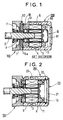
- FIG. 1 there is a longitudinal sectional view showing the first end of the stator 1 of the vacuum pump 100, with a motor shaft 2 extending the pump rotor not shown.
- the driving shaft 2 is engaged in a motor block 200 while being secured to the motor rotor 3.
- the motor rotor 3 is rotatably mounted on bearings inside the motor stator 4 comprising a stator winding 11 fed by electrical conductors not shown.
- the motor stator assembly 4 - motor rotor 3 is inserted in a motor housing 5.
- Seals can seal around the motor shaft 2 at the inlet of the motor housing 5, to isolate as much as possible the interior atmosphere of the motor housing 5 with respect to the upstream compartment 7 containing a set of coupling gears 8 between two parallel rotors of the vacuum pump 100.
- the gear set 8 transmits the rotational movement between both rotors, only one of the rotors being coupled in line with the drive shaft 2.
- the upstream compartment 7 of the gears 8 contains lubricating oil of the gear.
- an additional bearing 15a is placed between the gears 8 and the motor rotor 3.
- the known structure illustrated in FIG. figure 1 comprises a coaxial bell-shaped liner 9, the base 10 of which is sealingly embedded around its entire periphery between two parts of the motor casing 5, namely a main part 51 and a fixing base 52.
- the waterproof jacket 9 comprises a cylindrical intermediate portion 90 which is engaged in the air gap between the motor stator 4 and the motor rotor 3, and which is connected on the one hand to the base of the liner and to a top 91.
- a first disadvantage of such a known structure is its complexity, in that it is necessary to assemble and to provide several parts, including the sealed liner 9, and the two-part engine housing 51 and 52. This increases the cost of realization of the vacuum pump.
- a second disadvantage is that the presence of the cylindrical intermediate portion 90 of the sealed liner 9 engaged in the air gap between the motor stator 4 and the motor rotor 3 requires keeping a gap of relatively large thickness, which increases the consumption. of electrical energy necessary for driving the vacuum pump 100.
- Another disadvantage is that the presence of the sealed liner 9 leads to increasing the length of the engine, by moving the motor stator 4 and the motor rotor 3 away from the vacuum pump 100, increasing the door-to-door false of the motor shaft; this increases the vibration of the motor, and the noise generated by the vacuum pump assembly 100 - motor block 200, and requires the presence of the additional bearing 15a between the gears 8 and the motor rotor 3.
- Another disadvantage is also that the waterproof jacket, made of metal, is subjected to an alternating magnetic field in the air gap of the motor. This results in induction currents in the material forming the sealed jacket, energy losses and additional heating of the engine. These losses increase with the frequency of the magnetic field, and become prohibitive in a four-pole motor powered with double frequency.
- JP 07 317673 a screw pump for various fluids.
- the drive motor is disposed in an intermediate region of one of the rotor shafts, between the shaft coupling gears and the pump rotors.
- the crankcase is separate from the coupling gear housing.
- the structure is neither planned nor adapted to solve the specific problems of vacuum pump sealing.
- the object of the present invention is in particular to avoid the drawbacks of known vacuum pump structures, by proposing a new double rotor vacuum pump pumping unit structure associated with a motor whose sealing is at the simpler level less expensive, and more efficient.
- the purpose of the invention is to eliminate the watertight liner 9, by replacing it with other means to effectively seal against the migration of oil and gases through the engine to the atmosphere.
- the one-piece common casing has an intermediate wall between a first compartment containing the motor and a second compartment containing the gear set, with a passage for the drive shaft and with a dynamic seal to ensure sealing around the motor shaft between the first compartment and the second compartment.
- the one-piece common housing may advantageously comprise an axial end opening sealingly closed by a shutter door.
- a further vibration reduction is obtained by providing that the one-piece common housing is connected to the first end of the pump stator via a bearing support comprising a first guide bearing of the motor shaft disposed as close to the engine. This reduces the cantilever of the motor shaft.
- the reduction in length and cantilever is further promoted by the fact that the impregnation of the motor stator in the sealed resin allows to bring it closer to its housing, because the isolation distances can be reduced by the dielectric quality of the waterproof resin.
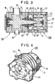
- a vacuum pump pumping unit according to the invention as illustrated on the Figures 2 to 4 comprises a double rotor vacuum pump 100 driven by a motor unit 200 supplied with electrical energy by a supply line 12.
- the vacuum pump 100 comprises a pump stator 1 having at least one axial inner cavity 13 in which are housed two parallel pump rotors rotatably mounted on corresponding bearings.
- a pump stator 1 having at least one axial inner cavity 13 in which are housed two parallel pump rotors rotatably mounted on corresponding bearings.
- the pump rotors 14 held in the pump stator 1 at its first end by a first bearing 15 and held at its second end by a second bearing 16.
- the two pump rotors such as the pump rotor 14 are coupled at their first end by a set of gears 17 enclosed in an oil sump 18.
- the first end of the pump rotor 14 is extended by the coaxial motor shaft 2 penetrating into the motor housing 5.
- the motor shaft 2 is engaged in the motor rotor 3, itself rotatably mounted in the motor stator 4 of the motor housing 5.
- the motor stator 4 comprises a stator winding 11 ( figure 2 ).
- the engine casing 5 and the oil sump 18 form a unitary common casing, advantageously made of metal and secured to the first end of the pump stator 1.
- the winding stator 11 of the motor unit 200 is embedded in a watertight resin 19 ( figure 2 ), which provides oil and gas tightness, preventing the outflow of oil and gas along the conductors of the power line 12 of the engine.
- the one-piece common housing 5, 18 has an axial end opening 20, sealingly closed by a shutter 21 with the interposition of an annular seal 22.
- the one-piece common housing comprises, between the motor housing portion 5 and the oil sump portion 18, an intermediate wall 23, separating the first compartment 24 containing the motor 3, 4 and the second compartment 25 containing the gear set 17, with an axial passage for the drive shaft and with a dynamic seal 6 to ensure as much as possible a seal around the drive shaft 2 between the first compartment 24 and the second compartment 25.
- the one-piece common housing 5, 18 is connected to the first end of the pump stator 1 via a bearing support 26 comprising the first bearing 15 for guiding the driving shaft 2.
- the first bearing 15 is placed closer to the engine block 200, to reduce the cantilever of the motor shaft 2.
- suction inlet 27 and the discharge outlet 28 of the vacuum pump 100 are also distinguished.
- the engine casing 5 comprises a duct 29 for conduction of cooling fluid.
- the structure according to the invention simultaneously ensures a better cooling of the pump stator part 1 close to the engine block 200, thanks to the continuous metal structure formed by the unitary common housing 5, 18, distinct from the sealed resin which is confined to the interior of said one-piece housing 5, 18. Also, by shortening the cantilever of the drive shaft 2, the vibrations are avoided and the noise generated by the vacuum pumping unit is reduced. It thus becomes possible to avoid the use of an additional bearing (15a, Figure 1 ) between the gears 17 and the motor rotor 3. In other words, as shown in FIG. figure 3 , the drive shaft 2 is then cantilevered from the first guide bearing 15, that is to say along the motor shaft section 2 carrying the motor rotor 3 and the gears 17.
- the length of the motor stator, and the resulting cantilever can be further reduced, for an identical motor torque, by using a motor 4, 4 four-pole powered double frequency 2F (in practice 200 Hz for example ), instead of a two-pole motor powered at a single frequency F (in practice 100 Hz for example). Due to the absence of airtight liner in the air gap, the use of a 2F dual-frequency powered four-pole motor is possible without creating excessive losses of performance. This was not possible with the known sealed jacket structures, since 2F dual frequency operation created excessive yield losses.
Landscapes
- Engineering & Computer Science (AREA)
- Mechanical Engineering (AREA)
- General Engineering & Computer Science (AREA)
- Connection Of Motors, Electrical Generators, Mechanical Devices, And The Like (AREA)
- Applications Or Details Of Rotary Compressors (AREA)
- Motor Or Generator Frames (AREA)
- Rotary Pumps (AREA)
- Saccharide Compounds (AREA)
- Jet Pumps And Other Pumps (AREA)
- Pharmaceuticals Containing Other Organic And Inorganic Compounds (AREA)
Applications Claiming Priority (3)
| Application Number | Priority Date | Filing Date | Title |
|---|---|---|---|
| FR0009401 | 2000-07-18 | ||
| FR0009401A FR2812040B1 (fr) | 2000-07-18 | 2000-07-18 | Carter monobloc pour pompe a vide |
| PCT/FR2001/002314 WO2002006675A2 (fr) | 2000-07-18 | 2001-07-17 | Carter monobloc pour pompe a vide |
Publications (2)
| Publication Number | Publication Date |
|---|---|
| EP1301712A2 EP1301712A2 (fr) | 2003-04-16 |
| EP1301712B1 true EP1301712B1 (fr) | 2009-02-25 |
Family
ID=8852631
Family Applications (1)
| Application Number | Title | Priority Date | Filing Date |
|---|---|---|---|
| EP01958136A Expired - Lifetime EP1301712B1 (fr) | 2000-07-18 | 2001-07-17 | Carter monobloc pour pompe a vide |
Country Status (7)
| Country | Link |
|---|---|
| US (1) | US6644942B2 (enExample) |
| EP (1) | EP1301712B1 (enExample) |
| JP (1) | JP2004504537A (enExample) |
| AT (1) | ATE423906T1 (enExample) |
| DE (1) | DE60137772D1 (enExample) |
| FR (1) | FR2812040B1 (enExample) |
| WO (1) | WO2002006675A2 (enExample) |
Families Citing this family (20)
| Publication number | Priority date | Publication date | Assignee | Title |
|---|---|---|---|---|
| GB0208742D0 (en) | 2002-04-17 | 2002-05-29 | Bradford Particle Design Ltd | Particulate materials |
| JP2003269345A (ja) * | 2002-03-13 | 2003-09-25 | Aisin Seiki Co Ltd | 電動オイルポンプ |
| US7582284B2 (en) | 2002-04-17 | 2009-09-01 | Nektar Therapeutics | Particulate materials |
| JP4085969B2 (ja) * | 2003-11-27 | 2008-05-14 | 株式会社豊田自動織機 | 電動ルーツ型圧縮機 |
| JP2006002633A (ja) | 2004-06-16 | 2006-01-05 | Yamaha Marine Co Ltd | 水ジェット推進艇 |
| EP1754889B1 (en) * | 2004-06-28 | 2016-10-12 | Panasonic Corporation | Air pump |
| JP2006037730A (ja) | 2004-07-22 | 2006-02-09 | Yamaha Marine Co Ltd | 過給式エンジンの吸気装置 |
| JP2006077699A (ja) * | 2004-09-10 | 2006-03-23 | Yamaha Marine Co Ltd | 過給装置の潤滑構造 |
| JP2006083713A (ja) * | 2004-09-14 | 2006-03-30 | Yamaha Marine Co Ltd | 過給装置の潤滑構造 |
| JP2007062432A (ja) | 2005-08-29 | 2007-03-15 | Yamaha Marine Co Ltd | 小型滑走艇 |
| JP4614853B2 (ja) | 2005-09-26 | 2011-01-19 | ヤマハ発動機株式会社 | 過給機の取付構造 |
| JP2008025477A (ja) * | 2006-07-21 | 2008-02-07 | Jtekt Corp | 電動ポンプ |
| ES2538082T3 (es) | 2007-02-11 | 2015-06-17 | Map Pharmaceuticals Inc | Método de administración terapéutica de DHE para permitir el rápido alivio de migraña mientras que se minimiza el perfil de efectos secundarios |
| JP4762301B2 (ja) * | 2008-12-19 | 2011-08-31 | 三菱電機株式会社 | 圧縮機用電動機及び圧縮機及び冷凍サイクル装置 |
| FR2943744A1 (fr) * | 2009-03-24 | 2010-10-01 | Inergy Automotive Systems Res | Pompe rotative |
| CN103107647B (zh) * | 2011-11-11 | 2015-06-03 | 中国科学院沈阳科学仪器股份有限公司 | 一种干式真空泵用电机 |
| EP2935894A1 (de) * | 2012-12-20 | 2015-10-28 | Sulzer Management AG | Mehrphasenpumpe mit abscheider, wobei das prozessfluid die pumpe schmiert und kühlt |
| AU2013361337A1 (en) | 2012-12-21 | 2015-07-09 | Map Pharmaceuticals, Inc. | 8'-Hydroxy-Dihydroergotamine compounds and compositions |
| EP3597922B1 (en) * | 2018-07-19 | 2024-08-28 | Agilent Technologies, Inc. (A Delaware Corporation) | Vacuum pumping system having an oil-lubricated vacuum pump |
| CN111963427B (zh) * | 2019-05-20 | 2022-06-14 | 复盛实业(上海)有限公司 | 螺旋式压缩机 |
Family Cites Families (22)
| Publication number | Priority date | Publication date | Assignee | Title |
|---|---|---|---|---|
| US2940661A (en) * | 1957-01-14 | 1960-06-14 | Heraeus Gmbh W C | Vacuum pumps |
| JPS57189246U (enExample) * | 1981-05-26 | 1982-12-01 | ||
| JPS60259791A (ja) * | 1984-06-04 | 1985-12-21 | Hitachi Ltd | オイルフリ−スクリユ−真空ポンプ |
| JPS63277885A (ja) * | 1987-05-06 | 1988-11-15 | Kobe Steel Ltd | オイルフリ−スクリュ式真空ポンプ |
| FR2637655B1 (fr) * | 1988-10-07 | 1994-01-28 | Alcatel Cit | Machine rotative du type pompe a vis |
| JPH0515101A (ja) * | 1991-06-28 | 1993-01-22 | Asmo Co Ltd | 樹脂モールド型回転電機 |
| JPH05240181A (ja) * | 1991-07-09 | 1993-09-17 | Ebara Corp | 多段真空ポンプ装置 |
| JPH0587076A (ja) * | 1991-09-27 | 1993-04-06 | Ebara Corp | スクリユー式真空ポンプ |
| JPH0569389U (ja) * | 1992-02-21 | 1993-09-21 | セイコー精機株式会社 | ドライ真空ポンプ |
| IT1259848B (it) * | 1992-11-27 | 1996-03-28 | Hydor Srl | Motore elettrico sincrono, particolarmente per pompe immergibili e pompa incorporante tale motore |
| JP3874430B2 (ja) * | 1994-05-25 | 2007-01-31 | 株式会社荏原製作所 | スクリュー流体機械 |
| JPH08100779A (ja) * | 1994-10-04 | 1996-04-16 | Matsushita Electric Ind Co Ltd | 真空ポンプ |
| DE69625401T2 (de) * | 1995-03-20 | 2003-10-30 | Ebara Corp., Tokio/Tokyo | Vakuumpumpe |
| JP3315581B2 (ja) * | 1995-03-20 | 2002-08-19 | 株式会社荏原製作所 | 真空ポンプ |
| US5904473A (en) * | 1995-06-21 | 1999-05-18 | Sihi Industry Consult Gmbh | Vacuum pump |
| JPH1155923A (ja) * | 1997-07-30 | 1999-02-26 | Mitsuba Corp | ブラシレスモータ |
| JPH11356022A (ja) * | 1998-06-03 | 1999-12-24 | Mitsubishi Electric Corp | モールドモータ |
| JP2000170680A (ja) * | 1998-09-30 | 2000-06-20 | Aisin Seiki Co Ltd | 真空ポンプ |
| JP4185598B2 (ja) * | 1998-10-02 | 2008-11-26 | 株式会社日立産機システム | 油冷式スクリュー圧縮機 |
| US6069421A (en) * | 1999-08-30 | 2000-05-30 | Electric Boat Corporation | Electric motor having composite encapsulated stator and rotor |
| JP3562763B2 (ja) * | 2000-01-31 | 2004-09-08 | 東芝テック株式会社 | インライン型ポンプ |
| US6457950B1 (en) * | 2000-05-04 | 2002-10-01 | Flowserve Management Company | Sealless multiphase screw-pump-and-motor package |
-
2000
- 2000-07-18 FR FR0009401A patent/FR2812040B1/fr not_active Expired - Fee Related
-
2001
- 2001-07-17 JP JP2002512545A patent/JP2004504537A/ja active Pending
- 2001-07-17 US US10/088,168 patent/US6644942B2/en not_active Expired - Fee Related
- 2001-07-17 EP EP01958136A patent/EP1301712B1/fr not_active Expired - Lifetime
- 2001-07-17 DE DE60137772T patent/DE60137772D1/de not_active Expired - Lifetime
- 2001-07-17 WO PCT/FR2001/002314 patent/WO2002006675A2/fr not_active Ceased
- 2001-07-17 AT AT01958136T patent/ATE423906T1/de not_active IP Right Cessation
Also Published As
| Publication number | Publication date |
|---|---|
| JP2004504537A (ja) | 2004-02-12 |
| FR2812040A1 (fr) | 2002-01-25 |
| DE60137772D1 (de) | 2009-04-09 |
| US6644942B2 (en) | 2003-11-11 |
| EP1301712A2 (fr) | 2003-04-16 |
| WO2002006675A2 (fr) | 2002-01-24 |
| WO2002006675A3 (fr) | 2002-03-14 |
| US20020150484A1 (en) | 2002-10-17 |
| FR2812040B1 (fr) | 2003-02-07 |
| ATE423906T1 (de) | 2009-03-15 |
Similar Documents
| Publication | Publication Date | Title |
|---|---|---|
| EP1301712B1 (fr) | Carter monobloc pour pompe a vide | |
| BE1014892A5 (fr) | Compresseur a vis sans huile. | |
| EP0882892B1 (fr) | Machine du type scroll | |
| CA2606069C (fr) | Arbre d'entrainement de boitier a engrenages de machines auxiliaires d'un turboreacteur; machine auxiliaire supplementaire modulaire | |
| EP0499504B1 (fr) | Machine tournante du type compresseur ou turbine pour la compression ou la détente d'un gaz dangereux | |
| FR2559847A1 (fr) | Machine a volutes pour comprimer un fluide | |
| FR2574870A1 (fr) | Appareil de deplacement de fluide de type a spirale | |
| CA2621837C (fr) | Systeme de deshuilage pour moteur d'aeronef | |
| JPS6042329B2 (ja) | 内燃機関、特に単列多シリンダ内燃機関 | |
| EP0097549B1 (fr) | Dispositif pour réaliser l'étanchéite d'un moteur immergeable et moteur s'y rapportant | |
| FR3114353A1 (fr) | Joint dynamique amélioré pour l’étanchéité d’un module de moteur d’aéronef | |
| EP3833872B1 (fr) | Turbomachine à étages multiples | |
| FR2548752A1 (fr) | Joint liquide pour gaz avec balayage de fluide | |
| EP3999729B1 (fr) | Réducteur à train épicycloïdal pour une turbomachine | |
| EP3999730B1 (fr) | Réducteur à train épicycloïdal pour une turbomachine | |
| FR2572770A1 (fr) | Moteur rotatif a combustion interne | |
| FR2565295A1 (fr) | Pompe a vide rotative etanchee dans l'huile | |
| FR2986568A1 (fr) | Dispositif d'etancheite avec joint hydraulique du passage d'un arbre rotatif au travers d'une paroi d'une enceinte. | |
| EP3907391B1 (fr) | Relais d'accessoires | |
| EP4077887A1 (fr) | Turbogenerateur pour aeronef, comprenant un système d'huile amélioré | |
| WO2016207544A1 (fr) | Support de roulements | |
| EP1473462B1 (fr) | Groupe compresseur à montage en cartouche | |
| FR2760786A1 (fr) | Moteur thermique circulaire a mouvements oscillants | |
| FR3135755A1 (fr) | Boitier de relais d’accessoires pour une turbomachine | |
| FR2520061A1 (fr) | Joint d'etancheite hydrodynamique de traversee d'arbre pour compresseurs a haute pression |
Legal Events
| Date | Code | Title | Description |
|---|---|---|---|
| PUAI | Public reference made under article 153(3) epc to a published international application that has entered the european phase |
Free format text: ORIGINAL CODE: 0009012 |
|
| 17P | Request for examination filed |
Effective date: 20020328 |
|
| AK | Designated contracting states |
Designated state(s): AT BE CH CY DE DK ES FI FR GB GR IE IT LI LU MC NL PT SE TR |
|
| AX | Request for extension of the european patent |
Extension state: AL LT LV MK RO SI |
|
| 17Q | First examination report despatched |
Effective date: 20061221 |
|
| RAP1 | Party data changed (applicant data changed or rights of an application transferred) |
Owner name: ALCATEL LUCENT |
|
| GRAP | Despatch of communication of intention to grant a patent |
Free format text: ORIGINAL CODE: EPIDOSNIGR1 |
|
| GRAS | Grant fee paid |
Free format text: ORIGINAL CODE: EPIDOSNIGR3 |
|
| GRAA | (expected) grant |
Free format text: ORIGINAL CODE: 0009210 |
|
| AK | Designated contracting states |
Kind code of ref document: B1 Designated state(s): AT BE CH CY DE DK ES FI FR GB GR IE IT LI LU MC NL PT SE TR |
|
| REG | Reference to a national code |
Ref country code: GB Ref legal event code: FG4D Free format text: NOT ENGLISH |
|
| REG | Reference to a national code |
Ref country code: CH Ref legal event code: EP |
|
| REG | Reference to a national code |
Ref country code: IE Ref legal event code: FG4D Free format text: LANGUAGE OF EP DOCUMENT: FRENCH |
|
| REF | Corresponds to: |
Ref document number: 60137772 Country of ref document: DE Date of ref document: 20090409 Kind code of ref document: P |
|
| PG25 | Lapsed in a contracting state [announced via postgrant information from national office to epo] |
Ref country code: FI Free format text: LAPSE BECAUSE OF FAILURE TO SUBMIT A TRANSLATION OF THE DESCRIPTION OR TO PAY THE FEE WITHIN THE PRESCRIBED TIME-LIMIT Effective date: 20090225 Ref country code: NL Free format text: LAPSE BECAUSE OF FAILURE TO SUBMIT A TRANSLATION OF THE DESCRIPTION OR TO PAY THE FEE WITHIN THE PRESCRIBED TIME-LIMIT Effective date: 20090225 |
|
| NLV1 | Nl: lapsed or annulled due to failure to fulfill the requirements of art. 29p and 29m of the patents act | ||
| PG25 | Lapsed in a contracting state [announced via postgrant information from national office to epo] |
Ref country code: SE Free format text: LAPSE BECAUSE OF FAILURE TO SUBMIT A TRANSLATION OF THE DESCRIPTION OR TO PAY THE FEE WITHIN THE PRESCRIBED TIME-LIMIT Effective date: 20090525 Ref country code: AT Free format text: LAPSE BECAUSE OF FAILURE TO SUBMIT A TRANSLATION OF THE DESCRIPTION OR TO PAY THE FEE WITHIN THE PRESCRIBED TIME-LIMIT Effective date: 20090225 |
|
| REG | Reference to a national code |
Ref country code: IE Ref legal event code: FD4D |
|
| PG25 | Lapsed in a contracting state [announced via postgrant information from national office to epo] |
Ref country code: DK Free format text: LAPSE BECAUSE OF FAILURE TO SUBMIT A TRANSLATION OF THE DESCRIPTION OR TO PAY THE FEE WITHIN THE PRESCRIBED TIME-LIMIT Effective date: 20090225 Ref country code: PT Free format text: LAPSE BECAUSE OF FAILURE TO SUBMIT A TRANSLATION OF THE DESCRIPTION OR TO PAY THE FEE WITHIN THE PRESCRIBED TIME-LIMIT Effective date: 20090812 Ref country code: ES Free format text: LAPSE BECAUSE OF FAILURE TO SUBMIT A TRANSLATION OF THE DESCRIPTION OR TO PAY THE FEE WITHIN THE PRESCRIBED TIME-LIMIT Effective date: 20090605 Ref country code: IE Free format text: LAPSE BECAUSE OF FAILURE TO SUBMIT A TRANSLATION OF THE DESCRIPTION OR TO PAY THE FEE WITHIN THE PRESCRIBED TIME-LIMIT Effective date: 20090225 |
|
| PLBE | No opposition filed within time limit |
Free format text: ORIGINAL CODE: 0009261 |
|
| STAA | Information on the status of an ep patent application or granted ep patent |
Free format text: STATUS: NO OPPOSITION FILED WITHIN TIME LIMIT |
|
| BERE | Be: lapsed |
Owner name: ALCATEL LUCENT Effective date: 20090731 |
|
| 26N | No opposition filed |
Effective date: 20091126 |
|
| PG25 | Lapsed in a contracting state [announced via postgrant information from national office to epo] |
Ref country code: MC Free format text: LAPSE BECAUSE OF NON-PAYMENT OF DUE FEES Effective date: 20090731 |
|
| REG | Reference to a national code |
Ref country code: CH Ref legal event code: PL |
|
| PG25 | Lapsed in a contracting state [announced via postgrant information from national office to epo] |
Ref country code: CH Free format text: LAPSE BECAUSE OF NON-PAYMENT OF DUE FEES Effective date: 20090731 Ref country code: LI Free format text: LAPSE BECAUSE OF NON-PAYMENT OF DUE FEES Effective date: 20090731 |
|
| PG25 | Lapsed in a contracting state [announced via postgrant information from national office to epo] |
Ref country code: BE Free format text: LAPSE BECAUSE OF NON-PAYMENT OF DUE FEES Effective date: 20090731 |
|
| PG25 | Lapsed in a contracting state [announced via postgrant information from national office to epo] |
Ref country code: GR Free format text: LAPSE BECAUSE OF FAILURE TO SUBMIT A TRANSLATION OF THE DESCRIPTION OR TO PAY THE FEE WITHIN THE PRESCRIBED TIME-LIMIT Effective date: 20090526 |
|
| PG25 | Lapsed in a contracting state [announced via postgrant information from national office to epo] |
Ref country code: IT Free format text: LAPSE BECAUSE OF FAILURE TO SUBMIT A TRANSLATION OF THE DESCRIPTION OR TO PAY THE FEE WITHIN THE PRESCRIBED TIME-LIMIT Effective date: 20090225 |
|
| PG25 | Lapsed in a contracting state [announced via postgrant information from national office to epo] |
Ref country code: LU Free format text: LAPSE BECAUSE OF NON-PAYMENT OF DUE FEES Effective date: 20090717 |
|
| PG25 | Lapsed in a contracting state [announced via postgrant information from national office to epo] |
Ref country code: TR Free format text: LAPSE BECAUSE OF FAILURE TO SUBMIT A TRANSLATION OF THE DESCRIPTION OR TO PAY THE FEE WITHIN THE PRESCRIBED TIME-LIMIT Effective date: 20090225 |
|
| PG25 | Lapsed in a contracting state [announced via postgrant information from national office to epo] |
Ref country code: CY Free format text: LAPSE BECAUSE OF FAILURE TO SUBMIT A TRANSLATION OF THE DESCRIPTION OR TO PAY THE FEE WITHIN THE PRESCRIBED TIME-LIMIT Effective date: 20090225 |
|
| PGFP | Annual fee paid to national office [announced via postgrant information from national office to epo] |
Ref country code: FR Payment date: 20110804 Year of fee payment: 11 |
|
| PGFP | Annual fee paid to national office [announced via postgrant information from national office to epo] |
Ref country code: GB Payment date: 20110726 Year of fee payment: 11 Ref country code: DE Payment date: 20110804 Year of fee payment: 11 |
|
| GBPC | Gb: european patent ceased through non-payment of renewal fee |
Effective date: 20120717 |
|
| REG | Reference to a national code |
Ref country code: FR Ref legal event code: ST Effective date: 20130329 |
|
| PG25 | Lapsed in a contracting state [announced via postgrant information from national office to epo] |
Ref country code: FR Free format text: LAPSE BECAUSE OF NON-PAYMENT OF DUE FEES Effective date: 20120731 Ref country code: DE Free format text: LAPSE BECAUSE OF NON-PAYMENT OF DUE FEES Effective date: 20130201 Ref country code: GB Free format text: LAPSE BECAUSE OF NON-PAYMENT OF DUE FEES Effective date: 20120717 |
|
| REG | Reference to a national code |
Ref country code: DE Ref legal event code: R119 Ref document number: 60137772 Country of ref document: DE Effective date: 20130201 |
|
| REG | Reference to a national code |
Ref country code: FR Ref legal event code: CA Effective date: 20150521 |
|
| REG | Reference to a national code |
Ref country code: FR Ref legal event code: CA Effective date: 20150521 |