EP1301693B1 - Gaswechselventilanordnung und ventilsitzkonstruktion mit ringförmiger nut - Google Patents
Gaswechselventilanordnung und ventilsitzkonstruktion mit ringförmiger nut Download PDFInfo
- Publication number
- EP1301693B1 EP1301693B1 EP01967166A EP01967166A EP1301693B1 EP 1301693 B1 EP1301693 B1 EP 1301693B1 EP 01967166 A EP01967166 A EP 01967166A EP 01967166 A EP01967166 A EP 01967166A EP 1301693 B1 EP1301693 B1 EP 1301693B1
- Authority
- EP
- European Patent Office
- Prior art keywords
- valve
- valve arrangement
- valve seat
- gas changeover
- arrangement according
- Prior art date
- Legal status (The legal status is an assumption and is not a legal conclusion. Google has not performed a legal analysis and makes no representation as to the accuracy of the status listed.)
- Expired - Lifetime
Links
Images
Classifications
-
- F—MECHANICAL ENGINEERING; LIGHTING; HEATING; WEAPONS; BLASTING
- F01—MACHINES OR ENGINES IN GENERAL; ENGINE PLANTS IN GENERAL; STEAM ENGINES
- F01L—CYCLICALLY OPERATING VALVES FOR MACHINES OR ENGINES
- F01L3/00—Lift-valve, i.e. cut-off apparatus with closure members having at least a component of their opening and closing motion perpendicular to the closing faces; Parts or accessories thereof
- F01L3/22—Valve-seats not provided for in preceding subgroups of this group; Fixing of valve-seats
-
- F—MECHANICAL ENGINEERING; LIGHTING; HEATING; WEAPONS; BLASTING
- F01—MACHINES OR ENGINES IN GENERAL; ENGINE PLANTS IN GENERAL; STEAM ENGINES
- F01L—CYCLICALLY OPERATING VALVES FOR MACHINES OR ENGINES
- F01L2820/00—Details on specific features characterising valve gear arrangements
- F01L2820/01—Absolute values
-
- F—MECHANICAL ENGINEERING; LIGHTING; HEATING; WEAPONS; BLASTING
- F02—COMBUSTION ENGINES; HOT-GAS OR COMBUSTION-PRODUCT ENGINE PLANTS
- F02F—CYLINDERS, PISTONS OR CASINGS, FOR COMBUSTION ENGINES; ARRANGEMENTS OF SEALINGS IN COMBUSTION ENGINES
- F02F7/00—Casings, e.g. crankcases
- F02F2007/0097—Casings, e.g. crankcases for large diesel engines
Definitions
- the invention relates to a gas exchange valve arrangement for internal combustion engines, in particular two-stroke large diesel engines.
- valve seat and valve disc In the past, attempts have already been made to do this by broadening the counteract mutual contact surfaces of valve seat and valve disc. The results, however, were not satisfactory. The reason is in it too see that wide contact surfaces between them Combustion residues prevent this from escaping, so that the Combustion residues are inevitably pressed into the contact surface. In addition, there is also a comparatively large contact surfaces strong heat transfer between valve plate and seat. This consists however in usually, in contrast to the valve disk, which is made of high temperature resistant, Material is produced and can take high temperatures off hardened steel. Due to a strong heat transfer, it can cause Microstructural changes and accordingly to a loss of hardness come.
- a gas exchange valve arrangement is known in which Area of the conical surface of the valve disk a circumferential groove is provided which is bounded laterally by circumferential, raised projections.
- the groove should by plastic material deformation by means of a press-on, a semi-circular profile having tool be generated, which is only one low depth allows.
- the groove accordingly has a depth of only about 0.1mm and therefore proves to be relatively shallow.
- the in the Cone surface of the valve plate depressed groove is intended to burn the combustion residues take up. Due to the small groove depth, however, there is a risk that the Residues in the groove are compressed and therefore in comparatively replenished in a short time.
- valve seat in particular two-stroke large diesel engines to the suggestion that a stationary, an associated flow channel embracing valve seat and a on the other hand has movable valve member, the one in sealing contact with the Valve seat can be brought valve disk, wherein in the area of at least one of mutual conical surfaces of valve seat and valve disc several, from each other spaced, annular circumferential, narrow sealing surfaces are provided, the at least on one side by an annular circumferential material recess limited and formed as ground surfaces with sharp side edges, and wherein the total width of all narrow sealing surfaces of a part of Gas exchange valve arrangement 0.5% to 2% of the mean diameter of the associated cone surface amounts.
- valve seat with annular, narrow sealing surfaces may be provided. This simplifies the production, since the hardened steel Existing valve seat before hardening comparatively easy to cut can be edited. In addition, this ensures that the Cone surface of the valve disk can be easily reground if necessary, without thereby limiting the depth of the narrow sealing surfaces Recessions is changed. It therefore also results in a simple Valve maintenance.
- the depth of the respective sealing surface defining recesses is advantageous greater than the expected thickness of the combustion residues. This is ensure that the combustion residues are not in the mentioned Recesses are pressed into and compacted into these and not fill, but that the combustion residues reliably crushed can and can escape. At the same time this results in a comparatively large capacity of said recesses, so that in this much to the combustion not participating air for cooling the Valve seat is present.
- a recess depth of more than 1 mm preferably achieved up to 3mm good results.
- a particularly preferable measure may be that of the Combustion chamber seen first, narrow sealing surface on the combustion chamber facing side is limited by a material recess, the at closed valve assembly through a narrow gap with the combustion chamber is connected and preferably one opposite a downstream Material recess has comparatively large capacity.
- the Air taken in here does not take up, despite the split connection to the combustion chamber participating in the combustion and causes a good cooling of the valve seat.
- the angle of inclination the mutual Konuns vom of valve seat and valve disc differently be, preferably differ by 0.5 ° from each other. This results especially narrow mutual contact surfaces and thus a special low mutual heat transfer and a very good comminution of taken combustion residues.
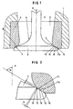
- the Figure 1 underlying gas exchange valve assembly which is at an outlet valve arrangement of the type mentioned above can act a stationary component 1, in the example of a two-stroke large diesel engine the cylinder head, assigned, at the entrance of a associated gas channel 2, in the example given at the entrance of the Exhaust gas ducts arranged, this encompassing valve seat 3 and a
- movable valve member 4 the one at the bottom of a a cooperating not shown here actuator Shaft 5 arranged valve plate 6, which in sealing contact on Valve seat 3 can be brought.
- the valve seat 3 and the valve disk 6 are with each other facing conical surfaces 7 and 8, which partially in sealing contact can be brought.
- the valve seat 3 is here to a in the associated, stationary component 1, in example mentioned in the cylinder head, inserted seat part 9 is formed.
- This consists of hardened steel.
- the seat part 9 containing the valve seat 3 becomes by not shown here, arranged in the component 1, with coolant cooled cooling channels, so that the hardness of the hardened steel preserved.
- the movable valve part 4 can be completely or at least in the area the valve plate 6 consist of a high temperature resistant material, the no cooling needed. The valve disk 6 therefore assumes a higher during operation Temperature at as the valve seat 3rd
- valve seat 3 and valve disc 6 do not come on their whole width in mutual plant, but only in the field of comparatively narrow annular sealing surfaces 10 example shown are two such, in the axial direction of each other distanced, within the upper and lower margins of each associated conical surface 7 and 8 arranged sealing surfaces 10 are provided.
- the material recesses 11, 11 a form comparatively large chambers, in FIG which can not hold combustion residues. These fall out of the said chambers out and therefore can escape with the exhaust gas, so that the formation of indentations is not to be feared.
- the narrow ones Sealing surfaces 10 cause a dismemberment of coming into their area Combustion residue, which facilitates their escape. The formation of Indentations and passages that are the starting point for blowholes form, is thus effectively prevented.
- the can be formed by the comparatively deep recesses 11 chambers also take in comparatively much air, which is not due to the combustion participates and accordingly gives a further cooling effect.
- the forming the sealing surfaces 10 profiling with MaterialausEnglishept 11, 11a and webs 12 may be in the region of the conical surface 8 of the valve disk or in the area the conical surfaces 7, 8 are provided by the valve seat and the valve plate: im illustrated, preferred example, the sealing surfaces 10 are only in the area of Conical surface 7 of the valve seat 3 is provided.
- the material recesses 11, 11a can be advantageously prepared before the curing of the seat part 9: After the hardening, the sealing surfaces 10 can be ground.
- the conical surface 8 of the valve disk 6 is also formed as a ground surface, from time to Time is reground. This is easily possible without the tread depth of Material recesses 11, 11a to change.
- the width b of the annular circumferential, narrow sealing surfaces 10 is selected so that that the total width of all of these sealing surfaces 10 of a part of Valve arrangement, here the valve seat 3, is dimensioned so that the total width all sealing surfaces 10 of a conical surface 7 or 8 in each case 0.5% to 2%, preferably 1% to 1.5%, of the mean diameter of the respective Cone surface is 7 or 8.
- the number of existing sealing surfaces 10 can appropriately be chosen so that a width b of the individual sealing surface 10 of at most 2mm results. This gave good results in experiments be achieved.
- the depth t of the sealing surfaces 10 laterally bounding Materialausappelsch 11, 11a is to be chosen larger than the expected thickness of the Combustion residues. A lower limit is in most cases at 0.4 to 0.5mm. However, the depth t may usefully be at least 1 mm, preferably more than 1 mm. For experiments with two-stroke large diesel engines were achieved with a depth up to 3mm good results. In the example shown, the depth t corresponds to that between the two Sealing surfaces 10 provided, so the combustion chamber near the sealing surface 10th downstream material recess 11 in about the width b.
- the inclination angle ⁇ of the conical surfaces 7, 8 relative to the valve axis a can be selected according to the needs of each case, for example in a range of 30 ° - 75 °. Preferred is a range of 45 ° - 60 °. A little Angle x gives comparatively steep conical surfaces 7,8 and thus high Contact forces. The lower region may therefore be advantageous for this case.
- the conical surfaces 7,8 angularly by about 0.5 ° from each other deviate, wherein the angle ⁇ of the valve seat side cone surface 7 by 0.5 ° greater than the angle ⁇ of the valve plate side cone surface 8, resulting in a results in radially outwardly opening gap. This measure can be the one above improve the knife effect mentioned above.
Landscapes
- Engineering & Computer Science (AREA)
- Mechanical Engineering (AREA)
- General Engineering & Computer Science (AREA)
- Lift Valve (AREA)
- Filling Or Discharging Of Gas Storage Vessels (AREA)
- Sealing With Elastic Sealing Lips (AREA)
- Valve-Gear Or Valve Arrangements (AREA)
- Details Of Valves (AREA)
- Multiple-Way Valves (AREA)
- Cylinder Crankcases Of Internal Combustion Engines (AREA)
- Quick-Acting Or Multi-Walled Pipe Joints (AREA)
- Feeding And Controlling Fuel (AREA)
- Check Valves (AREA)
Applications Claiming Priority (3)
| Application Number | Priority Date | Filing Date | Title |
|---|---|---|---|
| DE10034773 | 2000-07-18 | ||
| DE10034773A DE10034773B4 (de) | 2000-07-18 | 2000-07-18 | Gaswechselventilanordnung |
| PCT/EP2001/008099 WO2002006640A1 (de) | 2000-07-18 | 2001-07-13 | Gaswechselventilanordnung und ventilsitzkonstruktion mit rinförmiger nut |
Publications (2)
| Publication Number | Publication Date |
|---|---|
| EP1301693A1 EP1301693A1 (de) | 2003-04-16 |
| EP1301693B1 true EP1301693B1 (de) | 2004-06-09 |
Family
ID=7649237
Family Applications (1)
| Application Number | Title | Priority Date | Filing Date |
|---|---|---|---|
| EP01967166A Expired - Lifetime EP1301693B1 (de) | 2000-07-18 | 2001-07-13 | Gaswechselventilanordnung und ventilsitzkonstruktion mit ringförmiger nut |
Country Status (14)
| Country | Link |
|---|---|
| EP (1) | EP1301693B1 (pl) |
| JP (1) | JP3990275B2 (pl) |
| KR (1) | KR100689030B1 (pl) |
| CN (1) | CN100410501C (pl) |
| AT (1) | ATE268863T1 (pl) |
| AU (1) | AU2001287611A1 (pl) |
| DE (2) | DE10034773B4 (pl) |
| ES (1) | ES2222390T3 (pl) |
| NO (1) | NO335483B1 (pl) |
| PL (1) | PL200334B1 (pl) |
| PT (1) | PT1301693E (pl) |
| RU (1) | RU2242620C2 (pl) |
| TR (1) | TR200402016T4 (pl) |
| WO (1) | WO2002006640A1 (pl) |
Cited By (1)
| Publication number | Priority date | Publication date | Assignee | Title |
|---|---|---|---|---|
| US10989321B2 (en) | 2019-04-26 | 2021-04-27 | Caterpillar Inc. | Double-crowned valve seat insert having seating surface formed of hard-facing material |
Families Citing this family (18)
| Publication number | Priority date | Publication date | Assignee | Title |
|---|---|---|---|---|
| KR20040045752A (ko) * | 2002-11-25 | 2004-06-02 | 현대자동차주식회사 | 밸브 및 밸브시트의 접촉각이 변경된 cng 엔진의배기밸브 장치 |
| DE10354448A1 (de) * | 2003-11-21 | 2005-06-09 | Volkswagen Ag | Brennkraftmaschine mit Einlassventilanordnung |
| DE10361976B4 (de) * | 2003-11-21 | 2014-01-23 | Volkswagen Ag | Brennkraftmaschine mit Einlassventilanordnung |
| DE10354480A1 (de) * | 2003-11-21 | 2005-06-23 | Volkswagen Ag | Brennkraftmaschine mit Einlassventilanordnung |
| RU2341663C1 (ru) * | 2007-04-23 | 2008-12-20 | Государственное образовательное учреждение высшего профессионального образования "Елецкий государственный университет им. И.А. Бунина" | Газораспределительный механизм |
| RU2343295C1 (ru) * | 2007-04-23 | 2009-01-10 | Государственное образовательное учреждение высшего профессионального образования "Елецкий государственный университет им. И.А. Бунина" | Механизм газораспределения |
| US8127735B2 (en) * | 2009-03-09 | 2012-03-06 | GM Global Technology Operations LLC | Engine assembly with valve seat vent passages and method of forming |
| JP2011169213A (ja) * | 2010-02-18 | 2011-09-01 | Denso Corp | 排気ガス再循環バルブ |
| CN103244303A (zh) * | 2012-02-04 | 2013-08-14 | D.恩德里戈 | 飞机发动机的汽缸盖 |
| DE102014215870A1 (de) * | 2014-08-11 | 2016-02-11 | Robert Bosch Gmbh | Gasinjektor mit definierter Mikrostruktur an einer Dichtfläche |
| CN105604632A (zh) * | 2016-01-26 | 2016-05-25 | 上海高斯通船舶配件有限公司 | 有缓冲功能大功率四冲程内燃发动机气门座 |
| FR3055030B1 (fr) * | 2016-08-09 | 2020-04-24 | Renault S.A.S | Siege de soupape ameliore |
| RU2656080C1 (ru) * | 2016-11-30 | 2018-05-30 | Общество с ограниченной ответственностью "ФБТ" (ООО "ФБТ") | Впускной клапан двигателя внутреннего сгорания |
| US10934899B2 (en) * | 2018-11-13 | 2021-03-02 | Caterpillar Inc. | Valve seat insert for engine having double-crowned seating surface profiled for limiting valve recession |
| US10767520B1 (en) * | 2019-08-19 | 2020-09-08 | Caterpillar Inc. | Valve seat insert for long life natural gas lean burn engines |
| US10934902B1 (en) | 2019-11-06 | 2021-03-02 | Caterpillar Inc. | Valve seat insert for high power density and marine engines |
| CN115244280A (zh) * | 2020-03-11 | 2022-10-25 | 瓦锡兰芬兰有限公司 | 配置内燃活塞发动机中的气体交换阀组件的方法和气体交换阀 |
| GB2613396B (en) * | 2021-12-02 | 2024-03-20 | Delphi Tech Ip Ltd | Fuel injector suitable for gaseous fuel |
Family Cites Families (13)
| Publication number | Priority date | Publication date | Assignee | Title |
|---|---|---|---|---|
| FR1525285A (fr) * | 1967-04-04 | 1968-05-17 | Citroen Sa Andre | Perfectionnements apportés aux soupapes d'échappement |
| US4122817A (en) * | 1975-05-01 | 1978-10-31 | Trw Inc. | Internal combustion valve having an iron based hard-facing alloy contact surface |
| JPS548138A (en) * | 1977-06-22 | 1979-01-22 | Honda Motor Co Ltd | Method of making welded valve |
| DE2737689A1 (de) * | 1977-08-20 | 1979-02-22 | Maschf Augsburg Nuernberg Ag | Ventilanordnung |
| DK144217C (da) * | 1979-08-29 | 1982-06-21 | B & W Diesel As | Udstoedsventil til en forbraendingsmotor |
| DE2951317C2 (de) * | 1979-12-20 | 1982-06-16 | Krupp Mak Maschinenbau Gmbh, 2300 Kiel | Verfahren zur Herstellung von Teller-Ventilen |
| DE3140352A1 (de) * | 1981-10-10 | 1983-04-28 | Audi Nsu Auto Union Ag, 7107 Neckarsulm | Einspritz-brennkraftmaschine, insbesondere diesel-brennkraftmaschine mit direkteinspritzung |
| JPS59190414A (ja) * | 1983-04-13 | 1984-10-29 | Mitsubishi Heavy Ind Ltd | 弁装置 |
| JPS59196913A (ja) * | 1983-04-21 | 1984-11-08 | Mitsubishi Heavy Ind Ltd | 内燃機関の吸、排気弁装置 |
| SU1726794A1 (ru) * | 1989-05-29 | 1992-04-15 | Запорожский машиностроительный институт им.В.Я.Чубаря | Клапанные органы газораспределени двигател внутреннего сгорани |
| JPH08135520A (ja) * | 1994-11-14 | 1996-05-28 | Fuji Oozx Inc | 内燃機関用排気ガス還流制御弁装置 |
| JP3011076B2 (ja) * | 1995-10-31 | 2000-02-21 | トヨタ自動車株式会社 | 内燃機関のシリンダヘッド |
| DE19943264C2 (de) * | 1999-09-10 | 2002-07-25 | Man B & W Diesel As Kopenhagen | Hubkolbenmaschine, insbesondere Zweitakt-Großdieselmotor |
-
2000
- 2000-07-18 DE DE10034773A patent/DE10034773B4/de not_active Expired - Fee Related
-
2001
- 2001-07-13 TR TR2004/02016T patent/TR200402016T4/xx unknown
- 2001-07-13 AT AT01967166T patent/ATE268863T1/de not_active IP Right Cessation
- 2001-07-13 AU AU2001287611A patent/AU2001287611A1/en not_active Abandoned
- 2001-07-13 PT PT01967166T patent/PT1301693E/pt unknown
- 2001-07-13 ES ES01967166T patent/ES2222390T3/es not_active Expired - Lifetime
- 2001-07-13 DE DE50102540T patent/DE50102540D1/de not_active Expired - Lifetime
- 2001-07-13 EP EP01967166A patent/EP1301693B1/de not_active Expired - Lifetime
- 2001-07-13 PL PL362714A patent/PL200334B1/pl unknown
- 2001-07-13 JP JP2002512517A patent/JP3990275B2/ja not_active Expired - Fee Related
- 2001-07-13 CN CNB018129870A patent/CN100410501C/zh not_active Expired - Fee Related
- 2001-07-13 KR KR1020037000046A patent/KR100689030B1/ko not_active Expired - Fee Related
- 2001-07-13 RU RU2003104816/06A patent/RU2242620C2/ru not_active IP Right Cessation
- 2001-07-13 WO PCT/EP2001/008099 patent/WO2002006640A1/de not_active Ceased
-
2003
- 2003-01-15 NO NO20030207A patent/NO335483B1/no not_active IP Right Cessation
Cited By (1)
| Publication number | Priority date | Publication date | Assignee | Title |
|---|---|---|---|---|
| US10989321B2 (en) | 2019-04-26 | 2021-04-27 | Caterpillar Inc. | Double-crowned valve seat insert having seating surface formed of hard-facing material |
Also Published As
| Publication number | Publication date |
|---|---|
| EP1301693A1 (de) | 2003-04-16 |
| TR200402016T4 (tr) | 2004-10-21 |
| ES2222390T3 (es) | 2005-02-01 |
| KR100689030B1 (ko) | 2007-03-02 |
| ATE268863T1 (de) | 2004-06-15 |
| CN1443271A (zh) | 2003-09-17 |
| DE10034773A1 (de) | 2002-02-07 |
| PT1301693E (pt) | 2004-10-29 |
| CN100410501C (zh) | 2008-08-13 |
| NO20030207D0 (no) | 2003-01-15 |
| PL362714A1 (pl) | 2004-11-02 |
| DE10034773B4 (de) | 2006-08-17 |
| JP2004504525A (ja) | 2004-02-12 |
| WO2002006640A1 (de) | 2002-01-24 |
| NO335483B1 (no) | 2014-12-15 |
| DE50102540D1 (de) | 2004-07-15 |
| RU2242620C2 (ru) | 2004-12-20 |
| NO20030207L (no) | 2003-01-20 |
| JP3990275B2 (ja) | 2007-10-10 |
| KR20030016367A (ko) | 2003-02-26 |
| AU2001287611A1 (en) | 2002-01-30 |
| PL200334B1 (pl) | 2008-12-31 |
Similar Documents
| Publication | Publication Date | Title |
|---|---|---|
| DE10034773B4 (de) | Gaswechselventilanordnung | |
| DE69608608T2 (de) | Messerscheibe und Verfahren zu deren Herstellung | |
| EP0918927B1 (de) | Einspritzventil, insbesondere zum direkten einspritzen von kraftstoff in einen brennraum eines verbrennungsmotors | |
| EP0985802B1 (de) | Verfahren zum Ausbilden einer Filmkühlbohrung | |
| DE3929534C2 (pl) | ||
| DE102009028040B4 (de) | Kombinationswerkzeug für die Strukturierung von Oberflächen | |
| DE112020001509T5 (de) | Ventilsitzeinsatz mit doppelter krone mit sitzfläche aus aufschweissmaterial | |
| EP1546535A1 (de) | Mehrteiligen gekühlten kolben für einen verbrennungsmotor | |
| DE69809044T2 (de) | KOLBEN FüR EINEN ZWEITAKT-DIESELMOTOR | |
| EP1546547B1 (de) | Kraftstoffeinspritzventil für brennkraftmaschinen | |
| EP0835399A1 (de) | Flachdichtung und verfahren zu ihrer herstellung | |
| DE69311142T2 (de) | KOLBENOBERRING FüR BRENNKRAFTMASCHINEN | |
| DE3730411A1 (de) | Dichtung | |
| DE4309776A1 (de) | Kolben für Brennkraftmaschinen | |
| DE2709359A1 (de) | Kolbenring fuer hubkolben-brennkraftmaschinen | |
| DE2816923C2 (de) | Zylinderkopf für Brennkraftmaschinen | |
| EP4035808A1 (de) | Schneidelement und zerspanungswerkzeug | |
| EP2184540B1 (de) | Luftgekühlter Rostblock | |
| DE2733303C2 (de) | Vorkammer-Dieselmaschine | |
| EP0930464B1 (de) | Verfahren und Vorrichtung für das abgedichtete Befestigen einer Brennerelektrode | |
| DE19948891A1 (de) | Gedämpftes Werkzeug | |
| DE2825219A1 (de) | Abschleifbares material aus metall und verfahren zu seiner herstellung | |
| DE102021105287A1 (de) | Dichtelement für eine Turbomaschine, Formteil zur Herstellung eines Dichtelementes, Verfahren zur Herstellung und Anordnung eines Dichtelementes und Turbomaschine mit einem Dichtelement | |
| DE9301992U1 (de) | Kraftstoffeinspritzdüse für Brennkraftmaschinen | |
| DE2612323C3 (de) | Räumnadel |
Legal Events
| Date | Code | Title | Description |
|---|---|---|---|
| PUAI | Public reference made under article 153(3) epc to a published international application that has entered the european phase |
Free format text: ORIGINAL CODE: 0009012 |
|
| 17P | Request for examination filed |
Effective date: 20021121 |
|
| AK | Designated contracting states |
Designated state(s): AT BE CH CY DE DK ES FI FR GB GR IE IT LI LU MC NL PT SE TR |
|
| AX | Request for extension of the european patent |
Extension state: AL LT LV MK RO SI |
|
| GRAP | Despatch of communication of intention to grant a patent |
Free format text: ORIGINAL CODE: EPIDOSNIGR1 |
|
| GRAS | Grant fee paid |
Free format text: ORIGINAL CODE: EPIDOSNIGR3 |
|
| GRAA | (expected) grant |
Free format text: ORIGINAL CODE: 0009210 |
|
| AK | Designated contracting states |
Kind code of ref document: B1 Designated state(s): AT BE CH CY DE DK ES FI FR GB GR IE IT LI LU MC NL PT SE TR |
|
| PG25 | Lapsed in a contracting state [announced via postgrant information from national office to epo] |
Ref country code: CY Free format text: LAPSE BECAUSE OF FAILURE TO SUBMIT A TRANSLATION OF THE DESCRIPTION OR TO PAY THE FEE WITHIN THE PRESCRIBED TIME-LIMIT Effective date: 20040609 Ref country code: IE Free format text: LAPSE BECAUSE OF FAILURE TO SUBMIT A TRANSLATION OF THE DESCRIPTION OR TO PAY THE FEE WITHIN THE PRESCRIBED TIME-LIMIT Effective date: 20040609 Ref country code: FR Free format text: LAPSE BECAUSE OF FAILURE TO SUBMIT A TRANSLATION OF THE DESCRIPTION OR TO PAY THE FEE WITHIN THE PRESCRIBED TIME-LIMIT Effective date: 20040609 |
|
| REG | Reference to a national code |
Ref country code: GB Ref legal event code: FG4D Free format text: NOT ENGLISH |
|
| REG | Reference to a national code |
Ref country code: CH Ref legal event code: EP |
|
| PG25 | Lapsed in a contracting state [announced via postgrant information from national office to epo] |
Ref country code: AT Free format text: LAPSE BECAUSE OF NON-PAYMENT OF DUE FEES Effective date: 20040713 Ref country code: LU Free format text: LAPSE BECAUSE OF NON-PAYMENT OF DUE FEES Effective date: 20040713 |
|
| REF | Corresponds to: |
Ref document number: 50102540 Country of ref document: DE Date of ref document: 20040715 Kind code of ref document: P |
|
| REG | Reference to a national code |
Ref country code: IE Ref legal event code: FG4D Free format text: GERMAN |
|
| PG25 | Lapsed in a contracting state [announced via postgrant information from national office to epo] |
Ref country code: BE Free format text: LAPSE BECAUSE OF NON-PAYMENT OF DUE FEES Effective date: 20040731 Ref country code: MC Free format text: LAPSE BECAUSE OF NON-PAYMENT OF DUE FEES Effective date: 20040731 |
|
| REG | Reference to a national code |
Ref country code: SE Ref legal event code: TRGR |
|
| PG25 | Lapsed in a contracting state [announced via postgrant information from national office to epo] |
Ref country code: DK Free format text: LAPSE BECAUSE OF FAILURE TO SUBMIT A TRANSLATION OF THE DESCRIPTION OR TO PAY THE FEE WITHIN THE PRESCRIBED TIME-LIMIT Effective date: 20040909 |
|
| GBT | Gb: translation of ep patent filed (gb section 77(6)(a)/1977) |
Effective date: 20040831 |
|
| REG | Reference to a national code |
Ref country code: PT Ref legal event code: SC4A Free format text: AVAILABILITY OF NATIONAL TRANSLATION Effective date: 20040908 |
|
| REG | Reference to a national code |
Ref country code: GR Ref legal event code: EP Ref document number: 20040403107 Country of ref document: GR |
|
| LTIE | Lt: invalidation of european patent or patent extension |
Effective date: 20040609 |
|
| REG | Reference to a national code |
Ref country code: IE Ref legal event code: FD4D |
|
| BERE | Be: lapsed |
Owner name: MAN B & W DIESEL A/S Effective date: 20040731 |
|
| REG | Reference to a national code |
Ref country code: ES Ref legal event code: FG2A Ref document number: 2222390 Country of ref document: ES Kind code of ref document: T3 |
|
| PLBE | No opposition filed within time limit |
Free format text: ORIGINAL CODE: 0009261 |
|
| STAA | Information on the status of an ep patent application or granted ep patent |
Free format text: STATUS: NO OPPOSITION FILED WITHIN TIME LIMIT |
|
| 26N | No opposition filed |
Effective date: 20050310 |
|
| EN | Fr: translation not filed | ||
| BERE | Be: lapsed |
Owner name: *MAN B & W DIESEL A/S Effective date: 20040731 |
|
| PGFP | Annual fee paid to national office [announced via postgrant information from national office to epo] |
Ref country code: NL Payment date: 20190719 Year of fee payment: 19 |
|
| PGFP | Annual fee paid to national office [announced via postgrant information from national office to epo] |
Ref country code: DE Payment date: 20190719 Year of fee payment: 19 Ref country code: TR Payment date: 20190708 Year of fee payment: 19 Ref country code: SE Payment date: 20190719 Year of fee payment: 19 Ref country code: PT Payment date: 20190708 Year of fee payment: 19 Ref country code: ES Payment date: 20190822 Year of fee payment: 19 Ref country code: IT Payment date: 20190730 Year of fee payment: 19 Ref country code: FI Payment date: 20190722 Year of fee payment: 19 |
|
| PGFP | Annual fee paid to national office [announced via postgrant information from national office to epo] |
Ref country code: GR Payment date: 20190716 Year of fee payment: 19 |
|
| PGFP | Annual fee paid to national office [announced via postgrant information from national office to epo] |
Ref country code: GB Payment date: 20190719 Year of fee payment: 19 |
|
| PGFP | Annual fee paid to national office [announced via postgrant information from national office to epo] |
Ref country code: CH Payment date: 20190719 Year of fee payment: 19 |
|
| REG | Reference to a national code |
Ref country code: DE Ref legal event code: R119 Ref document number: 50102540 Country of ref document: DE |
|
| REG | Reference to a national code |
Ref country code: FI Ref legal event code: MAE |
|
| REG | Reference to a national code |
Ref country code: CH Ref legal event code: PL |
|
| REG | Reference to a national code |
Ref country code: SE Ref legal event code: EUG |
|
| REG | Reference to a national code |
Ref country code: NL Ref legal event code: MM Effective date: 20200801 |
|
| GBPC | Gb: european patent ceased through non-payment of renewal fee |
Effective date: 20200713 |
|
| PG25 | Lapsed in a contracting state [announced via postgrant information from national office to epo] |
Ref country code: CH Free format text: LAPSE BECAUSE OF NON-PAYMENT OF DUE FEES Effective date: 20200731 Ref country code: GR Free format text: LAPSE BECAUSE OF NON-PAYMENT OF DUE FEES Effective date: 20210210 Ref country code: LI Free format text: LAPSE BECAUSE OF NON-PAYMENT OF DUE FEES Effective date: 20200731 Ref country code: PT Free format text: LAPSE BECAUSE OF NON-PAYMENT OF DUE FEES Effective date: 20210215 Ref country code: NL Free format text: LAPSE BECAUSE OF NON-PAYMENT OF DUE FEES Effective date: 20200801 Ref country code: GB Free format text: LAPSE BECAUSE OF NON-PAYMENT OF DUE FEES Effective date: 20200713 Ref country code: FI Free format text: LAPSE BECAUSE OF NON-PAYMENT OF DUE FEES Effective date: 20200713 |
|
| PG25 | Lapsed in a contracting state [announced via postgrant information from national office to epo] |
Ref country code: DE Free format text: LAPSE BECAUSE OF NON-PAYMENT OF DUE FEES Effective date: 20210202 Ref country code: SE Free format text: LAPSE BECAUSE OF NON-PAYMENT OF DUE FEES Effective date: 20200714 |
|
| PG25 | Lapsed in a contracting state [announced via postgrant information from national office to epo] |
Ref country code: PT Free format text: LAPSE BECAUSE OF EXPIRATION OF PROTECTION Effective date: 20210721 |
|
| REG | Reference to a national code |
Ref country code: ES Ref legal event code: FD2A Effective date: 20211201 |
|
| PG25 | Lapsed in a contracting state [announced via postgrant information from national office to epo] |
Ref country code: ES Free format text: LAPSE BECAUSE OF NON-PAYMENT OF DUE FEES Effective date: 20200714 |
|
| PG25 | Lapsed in a contracting state [announced via postgrant information from national office to epo] |
Ref country code: IT Free format text: LAPSE BECAUSE OF NON-PAYMENT OF DUE FEES Effective date: 20200713 |
|
| PG25 | Lapsed in a contracting state [announced via postgrant information from national office to epo] |
Ref country code: TR Free format text: LAPSE BECAUSE OF NON-PAYMENT OF DUE FEES Effective date: 20200713 |
|
| PG25 | Lapsed in a contracting state [announced via postgrant information from national office to epo] |
Ref country code: PT Free format text: LAPSE BECAUSE OF NON-PAYMENT OF DUE FEES Effective date: 20200813 |
|
| PG25 | Lapsed in a contracting state [announced via postgrant information from national office to epo] |
Ref country code: PT Free format text: LAPSE BECAUSE OF NON-PAYMENT OF DUE FEES Effective date: 20200813 |