EP1300552B1 - Drainagevorrichtung zum Flüssigkeitsbehälter - Google Patents
Drainagevorrichtung zum Flüssigkeitsbehälter Download PDFInfo
- Publication number
- EP1300552B1 EP1300552B1 EP01308435A EP01308435A EP1300552B1 EP 1300552 B1 EP1300552 B1 EP 1300552B1 EP 01308435 A EP01308435 A EP 01308435A EP 01308435 A EP01308435 A EP 01308435A EP 1300552 B1 EP1300552 B1 EP 1300552B1
- Authority
- EP
- European Patent Office
- Prior art keywords
- sump
- floor
- gutter
- drain aperture
- drain
- Prior art date
- Legal status (The legal status is an assumption and is not a legal conclusion. Google has not performed a legal analysis and makes no representation as to the accuracy of the status listed.)
- Expired - Lifetime
Links
- 239000012530 fluid Substances 0.000 title claims description 17
- 230000002093 peripheral effect Effects 0.000 claims description 15
- 238000000034 method Methods 0.000 claims description 9
- 238000002485 combustion reaction Methods 0.000 claims description 7
- 230000000284 resting effect Effects 0.000 claims description 2
- 239000003921 oil Substances 0.000 description 20
- 229910000838 Al alloy Inorganic materials 0.000 description 1
- 229910000851 Alloy steel Inorganic materials 0.000 description 1
- 229910001018 Cast iron Inorganic materials 0.000 description 1
- 238000004140 cleaning Methods 0.000 description 1
- 238000011109 contamination Methods 0.000 description 1
- 238000001816 cooling Methods 0.000 description 1
- 230000005484 gravity Effects 0.000 description 1
- 239000010687 lubricating oil Substances 0.000 description 1
- 238000005461 lubrication Methods 0.000 description 1
- 239000000463 material Substances 0.000 description 1
- 229910052751 metal Inorganic materials 0.000 description 1
- 239000002184 metal Substances 0.000 description 1
- 238000012986 modification Methods 0.000 description 1
- 230000004048 modification Effects 0.000 description 1
- 239000002990 reinforced plastic Substances 0.000 description 1
- 230000000717 retained effect Effects 0.000 description 1
- 239000010802 sludge Substances 0.000 description 1
- 239000010959 steel Substances 0.000 description 1
Images

Classifications
-
- F—MECHANICAL ENGINEERING; LIGHTING; HEATING; WEAPONS; BLASTING
- F01—MACHINES OR ENGINES IN GENERAL; ENGINE PLANTS IN GENERAL; STEAM ENGINES
- F01M—LUBRICATING OF MACHINES OR ENGINES IN GENERAL; LUBRICATING INTERNAL COMBUSTION ENGINES; CRANKCASE VENTILATING
- F01M11/00—Component parts, details or accessories, not provided for in, or of interest apart from, groups F01M1/00 - F01M9/00
- F01M11/0004—Oilsumps
-
- F—MECHANICAL ENGINEERING; LIGHTING; HEATING; WEAPONS; BLASTING
- F01—MACHINES OR ENGINES IN GENERAL; ENGINE PLANTS IN GENERAL; STEAM ENGINES
- F01M—LUBRICATING OF MACHINES OR ENGINES IN GENERAL; LUBRICATING INTERNAL COMBUSTION ENGINES; CRANKCASE VENTILATING
- F01M11/00—Component parts, details or accessories, not provided for in, or of interest apart from, groups F01M1/00 - F01M9/00
- F01M11/04—Filling or draining lubricant of or from machines or engines
-
- F—MECHANICAL ENGINEERING; LIGHTING; HEATING; WEAPONS; BLASTING
- F01—MACHINES OR ENGINES IN GENERAL; ENGINE PLANTS IN GENERAL; STEAM ENGINES
- F01M—LUBRICATING OF MACHINES OR ENGINES IN GENERAL; LUBRICATING INTERNAL COMBUSTION ENGINES; CRANKCASE VENTILATING
- F01M11/00—Component parts, details or accessories, not provided for in, or of interest apart from, groups F01M1/00 - F01M9/00
- F01M11/0004—Oilsumps
- F01M2011/002—Oilsumps with means for improving the stiffness
-
- F—MECHANICAL ENGINEERING; LIGHTING; HEATING; WEAPONS; BLASTING
- F01—MACHINES OR ENGINES IN GENERAL; ENGINE PLANTS IN GENERAL; STEAM ENGINES
- F01M—LUBRICATING OF MACHINES OR ENGINES IN GENERAL; LUBRICATING INTERNAL COMBUSTION ENGINES; CRANKCASE VENTILATING
- F01M11/00—Component parts, details or accessories, not provided for in, or of interest apart from, groups F01M1/00 - F01M9/00
- F01M11/0004—Oilsumps
- F01M2011/0066—Oilsumps with passages in the wall, e.g. for axles or fluid passages
Definitions
- lubricating oil drains into a sump from which the oil is drawn to be pumped around the lubrication circuit.
- the sump is conventionally a generally rectangular pan and is provided with a drain aperture closed by a drain plug.
- a closable drain aperture is located in the peripheral wall with at least the lowermost part of the drain aperture located within said at least one gutter.
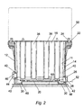
- the drain plugs 26 When it is desired to drain oil from the sump 10, one of the drain plugs 26 is removed, thereby opening the drain aperture 28. The oil in the sump is then free to flow out of the sump 10 through the drain aperture 28. As the oil flows through the drain aperture 28, the level of the oil in the sump falls. Because the gutters 30 are formed to be below the adjacent floor 20, as the oil level falls oil will tend to flow from the floor 20 into the gutter or gutters 30. Oil then flows along the gutter or gutters 30 and then through the drain aperture 28 until the oil level reaches the level of the lowermost part 29 of the drain aperture 28, this level being indicated at 52 in Figure 2. At this point the sump 10 will contain only the small quantity of oil which remains below level 44 in the gutter or gutters 30 in the lowermost portion 32 of the floor. The area of the floor 20 between the gutters 30 will be free of oil.
Landscapes
- Engineering & Computer Science (AREA)
- Mechanical Engineering (AREA)
- General Engineering & Computer Science (AREA)
- Lubrication Details And Ventilation Of Internal Combustion Engines (AREA)
Claims (14)
- Eine Wanne (10) für einen Verbrennungsmotor, die Folgendes beinhaltet:einen Kasten, der eine periphere Wand (11) und einen Boden (20) aufweist;wobei der Boden (20) mit mindestens einer Rinne (30), die an einen Abschnitt der peripheren Wand (11) angrenzt, gebildet ist; undeine erste schließbare Ablassöffnung (28), die mit mindestens dem niedrigsten Teil (29) der Ablassöffnung (28), der innerhalb der mindestens einen Rinne (30) lokalisiert ist, in der peripheren Wand (11) lokalisiert ist.
- Wanne gemäß Anspruch 1, die eine Ablassschraube (26) umfasst, die lösbar innerhalb der ersten Ablassöffnung (28) bereitgestellt ist.
- Wanne gemäß Anspruch 1 oder 2, wobei die periphere Wand (11) eine erste Seitenwand und eine zweite Seitenwand (12, 14) umfasst, und der Boden mit einer ersten Rinne und einer zweiten Rinne (30), die an die erste Seitenwand bzw. die zweite Seitenwand (12, 14) angrenzt, gebildet ist.
- Wanne gemäß Anspruch 3, wobei die erste Ablassöffnung (28) innerhalb der ersten Seitenwand (12) lokalisiert ist, und eine zweite schließbare Ablassöffnung (28) in der zweiten Seitenwand (14) lokalisiert ist, wobei mindestens der niedrigste Teil (29) der zweiten Ablassöffnung (28) innerhalb der zweiten Rinne (30) lokalisiert ist.
- Wanne gemäß Anspruch 3 oder 4, wobei die Rinnen (30) Stützschienen (48) bilden, die angepasst sind, um auf einer Stützoberfläche (60) zu ruhen.
- Wanne gemäß einem der vorhergehenden Ansprüche, wobei der Boden (20) und die Rinnen (30) in Richtung des Standorts der Ablassöffnung (28) abfallen.
- Wanne gemäß einem der Ansprüche 3 bis 5, wobei der Boden (20) einen niedrigsten Abschnitt (32) aufweist, in dem der Boden und die Rinnen (30) horizontal in Verwendung sind; wobei der Boden (20) mindestens einen abfallenden Abschnitt (34, 36), der an den niedrigsten Abschnitt (32) des Bodens angrenzt, aufweist, wobei der Boden und die Rinnen (30) in Richtung des niedrigsten Abschnitts (32) in Verwendung geneigt sind; und wobei jede Ablassöffnung (28) in einem niedrigen Abschnitt (40) der entsprechenden Seitenwand (12, 14), die an den niedrigsten Abschnitt (32) des Bodens angrenzt, lokalisiert ist.
- Wanne gemäß Anspruch 7, wobei die Seitenwände (12, 14) lokal in dem Bereich der niedrigen Abschnitte (40) der Seitenwände eine erhöhte Wanddicke aufweisen.
- Ein Verbrennungsmotor (50), der eine Wanne (10) gemäß einem der vorhergehenden Ansprüche aufweist.
- Ein Verfahren zum Ablassen von Flüssigkeit aus einer Wanne (10), die einen Boden (20) und mindestens eine schließbare Ablassöffnung (28) aufweist, wobei das Verfahren die folgenden Schritte beinhaltet:Aufmachen der mindestens einen Ablassöffnung (28); undVerursachen, dass die Flüssigkeit innerhalb der Wanne entlang mindestens einer Rinne (30), die in dem Boden der Wanne gebildet ist, und durch die mindestens eine Ablassöffnung (28) fließt.
- Verfahren gemäß Anspruch 10, wobei der Schritt des Flüssigkeitsflusses das Verursachen, dass die Flüssigkeit durch mindestens einen niedrigsten Teil (29) der mindestens einen Ablassöffnung (28) fließt, umfasst, wobei der niedrigste Teil (29) innerhalb der mindestens einen Rinne (30) lokalisiert ist.
- Verfahren gemäß Anspruch 10 oder 11, wobei die Wanne (10) eine periphere Wand (11) umfasst und die mindestens eine Ablassöffnung (28) in der peripheren Wand (11) der Wanne gebildet ist, und wobei der Schritt des Flüssigkeitsflusses das Verursachen, dass die Flüssigkeit innerhalb der Wanne entlang einer Rinne (30), die angrenzend an einen Abschnitt der peripheren Wand (11) lokalisiert ist, fließt, umfasst.
- Verfahren gemäß Anspruch 12, wobei die periphere Wand (11) eine erste Seitenwand und eine zweite Seitenwand (12, 14) umfasst und die Wanne eine erste schließbare Ablassöffnung und eine zweite schließbare Ablassöffnung (28), die in der ersten Seitenwand bzw. in der zweiten Seitenwand (12, 14) gebildet sind, umfasst, und wobei der Schritt des Flüssigkeitsflusses das Verursachen, dass die Flüssigkeit innerhalb der Wanne entlang der ersten Rinne und der zweiten Rinne (30), die angrenzend an der ersten Seitenwand bzw. der zweiten Seitenwand (12, 14) lokalisiert sind, fließt, umfasst.
- Verfahren gemäß Anspruch 10, wobei der Boden (20) der Wanne einen niedrigsten Abschnitt (32) aufweist, in dem der Boden und die mindestens eine Rinne (30) horizontal sind und mindestens ein abfallender Abschnitt (34, 36) an den niedrigsten Abschnitt (32) des Bodens angrenzt, wobei der Boden und die mindestens eine Rinne (30) in Richtung des niedrigsten Abschnitts geneigt sind, und wobei der Schritt des Flüssigkeitsflusses das Verursachen, dass die Flüssigkeit innerhalb der Wanne entlang der mindestens einen Rinne (30) zu dem niedrigsten Abschnitt (32) des Bodens und dann durch die Ablassöffnung (28) fließt, umfasst.
Priority Applications (3)
| Application Number | Priority Date | Filing Date | Title |
|---|---|---|---|
| EP01308435A EP1300552B1 (de) | 2001-10-02 | 2001-10-02 | Drainagevorrichtung zum Flüssigkeitsbehälter |
| DE2001627840 DE60127840T2 (de) | 2001-10-02 | 2001-10-02 | Drainagevorrichtung zum Flüssigkeitsbehälter |
| US10/303,682 US20040099481A1 (en) | 2001-10-02 | 2002-11-25 | Fluid sump drainage |
Applications Claiming Priority (2)
| Application Number | Priority Date | Filing Date | Title |
|---|---|---|---|
| EP01308435A EP1300552B1 (de) | 2001-10-02 | 2001-10-02 | Drainagevorrichtung zum Flüssigkeitsbehälter |
| US10/303,682 US20040099481A1 (en) | 2001-10-02 | 2002-11-25 | Fluid sump drainage |
Publications (2)
| Publication Number | Publication Date |
|---|---|
| EP1300552A1 EP1300552A1 (de) | 2003-04-09 |
| EP1300552B1 true EP1300552B1 (de) | 2007-04-11 |
Family
ID=32870702
Family Applications (1)
| Application Number | Title | Priority Date | Filing Date |
|---|---|---|---|
| EP01308435A Expired - Lifetime EP1300552B1 (de) | 2001-10-02 | 2001-10-02 | Drainagevorrichtung zum Flüssigkeitsbehälter |
Country Status (2)
| Country | Link |
|---|---|
| US (1) | US20040099481A1 (de) |
| EP (1) | EP1300552B1 (de) |
Families Citing this family (1)
| Publication number | Priority date | Publication date | Assignee | Title |
|---|---|---|---|---|
| DE102020134074A1 (de) * | 2020-12-18 | 2022-06-23 | Bayerische Motoren Werke Aktiengesellschaft | Ölwanne mit Ölablassschraube |
Family Cites Families (18)
| Publication number | Priority date | Publication date | Assignee | Title |
|---|---|---|---|---|
| US1970754A (en) * | 1933-04-10 | 1934-08-21 | Jonasen Myers | Bed pad |
| US2187247A (en) * | 1939-01-25 | 1940-01-16 | Russell H Nichols | Crankcase drain valve |
| US2577188A (en) * | 1948-04-01 | 1951-12-04 | Michael F Hall | Composite oil pan for engines |
| US3120237A (en) * | 1961-03-15 | 1964-02-04 | Pure Oil Co | Crankcase spray device |
| US3189126A (en) * | 1963-03-18 | 1965-06-15 | Mack Trucks | Engine crankcase |
| US3310133A (en) * | 1964-05-20 | 1967-03-21 | Forrest D Eaker | Remote operated oil drain |
| US3653464A (en) * | 1970-04-13 | 1972-04-04 | Gen Motors Corp | Engine oil pan |
| US4084655A (en) * | 1975-08-15 | 1978-04-18 | Emil Savron | Motor vehicles |
| US4114644A (en) * | 1977-02-08 | 1978-09-19 | Piper Eldon L | Recycling drain pan |
| US4592443A (en) * | 1983-02-01 | 1986-06-03 | Jack Simon | Sobriety interlock |
| DE3831308C1 (de) * | 1988-09-15 | 1990-01-18 | Dr.Ing.H.C. F. Porsche Ag, 7000 Stuttgart, De | |
| JPH0763032A (ja) * | 1993-08-27 | 1995-03-07 | Kubota Corp | 車両用エンジンのオイルパン装置 |
| FR2721976B1 (fr) * | 1994-07-04 | 1996-08-30 | Renault | Moteur a combustion interne a carter d'huile perfectionne et carter pour un tel moteur |
| US5482181A (en) * | 1995-03-20 | 1996-01-09 | Weaver; Donald L. | Portable liquid drain pan with cantilever extensions and pour spout |
| JP3360554B2 (ja) * | 1996-11-26 | 2002-12-24 | スズキ株式会社 | オイルパンのバッフルプレート構造 |
| US5863424A (en) * | 1998-05-05 | 1999-01-26 | Dana Corporation | Filter element for oil pans and filter element/oil pan combination |
| JP2000337123A (ja) * | 1999-05-24 | 2000-12-05 | Yamaha Motor Co Ltd | エンジン装置 |
| US6378639B1 (en) * | 2000-09-15 | 2002-04-30 | Patrick W. Murray | Oil drip pan assembly for a vehicle |
-
2001
- 2001-10-02 EP EP01308435A patent/EP1300552B1/de not_active Expired - Lifetime
-
2002
- 2002-11-25 US US10/303,682 patent/US20040099481A1/en not_active Abandoned
Also Published As
| Publication number | Publication date |
|---|---|
| EP1300552A1 (de) | 2003-04-09 |
| US20040099481A1 (en) | 2004-05-27 |
Similar Documents
| Publication | Publication Date | Title |
|---|---|---|
| US8776757B2 (en) | Transmission fluid pan | |
| US6237720B1 (en) | Engine oil pan including sediment basin and baffle configuration | |
| US6982379B2 (en) | Automotive electrical connection box and a method of mounting it | |
| EP1300552B1 (de) | Drainagevorrichtung zum Flüssigkeitsbehälter | |
| GB2538318A (en) | A sump | |
| US6520164B1 (en) | Crankcase ventilation oil drain tube | |
| EP1550814B1 (de) | Lagergehäuse mit einem aufgeteilten Ring für Öl-Drainage und -Sammlung | |
| DE60127840T2 (de) | Drainagevorrichtung zum Flüssigkeitsbehälter | |
| CN214464475U (zh) | 一种船用柴油机滤器凹凸集油盘 | |
| CN2448429Y (zh) | 油水分离器 | |
| CN206707797U (zh) | 内燃机油底壳 | |
| EP2184516B1 (de) | Fahrzeugwanne | |
| JP3713398B2 (ja) | 鉄道高架橋内部でのグリース阻集方法 | |
| JPS59396Y2 (ja) | グリ−ストラップ桝 | |
| EP1514620B1 (de) | Maschinengehäuse | |
| JPS643449Y2 (de) | ||
| JPS6214322Y2 (de) | ||
| CN207739357U (zh) | 一种地下车库隔油沉砂井 | |
| TH67087A (th) | เครื่องยนต์ | |
| JPH06336952A (ja) | オイルパン | |
| JPS61119586A (ja) | エスカレ−タあるいは動く歩動の集油器 | |
| CN209735100U (zh) | 一种压滤机滤水收集机构 | |
| RU2227787C1 (ru) | Установка для перколяционного выщелачивания алюминийсодержащих руд и спеков | |
| CA2896802C (en) | Grease interceptor system and method of installing a grease interceptor system | |
| JPS5839717B2 (ja) | 浮屋根式タンクの非常用ドレン |
Legal Events
| Date | Code | Title | Description |
|---|---|---|---|
| PUAI | Public reference made under article 153(3) epc to a published international application that has entered the european phase |
Free format text: ORIGINAL CODE: 0009012 |
|
| AK | Designated contracting states |
Kind code of ref document: A1 Designated state(s): AT BE CH CY DE DK ES FI FR GB GR IE IT LI LU MC NL PT SE TR |
|
| AX | Request for extension of the european patent |
Extension state: AL LT LV MK RO SI |
|
| 17P | Request for examination filed |
Effective date: 20030912 |
|
| AKX | Designation fees paid |
Designated state(s): DE FR GB |
|
| RBV | Designated contracting states (corrected) |
Designated state(s): DE FR GB |
|
| GRAP | Despatch of communication of intention to grant a patent |
Free format text: ORIGINAL CODE: EPIDOSNIGR1 |
|
| GRAS | Grant fee paid |
Free format text: ORIGINAL CODE: EPIDOSNIGR3 |
|
| GRAA | (expected) grant |
Free format text: ORIGINAL CODE: 0009210 |
|
| RAP1 | Party data changed (applicant data changed or rights of an application transferred) |
Owner name: PERKINS ENGINES COMPANY LIMITED |
|
| AK | Designated contracting states |
Kind code of ref document: B1 Designated state(s): DE FR GB |
|
| REG | Reference to a national code |
Ref country code: GB Ref legal event code: FG4D |
|
| REF | Corresponds to: |
Ref document number: 60127840 Country of ref document: DE Date of ref document: 20070524 Kind code of ref document: P |
|
| EN | Fr: translation not filed | ||
| PLBE | No opposition filed within time limit |
Free format text: ORIGINAL CODE: 0009261 |
|
| STAA | Information on the status of an ep patent application or granted ep patent |
Free format text: STATUS: NO OPPOSITION FILED WITHIN TIME LIMIT |
|
| 26N | No opposition filed |
Effective date: 20080114 |
|
| PG25 | Lapsed in a contracting state [announced via postgrant information from national office to epo] |
Ref country code: FR Free format text: LAPSE BECAUSE OF FAILURE TO SUBMIT A TRANSLATION OF THE DESCRIPTION OR TO PAY THE FEE WITHIN THE PRESCRIBED TIME-LIMIT Effective date: 20071207 |
|
| PG25 | Lapsed in a contracting state [announced via postgrant information from national office to epo] |
Ref country code: FR Free format text: LAPSE BECAUSE OF FAILURE TO SUBMIT A TRANSLATION OF THE DESCRIPTION OR TO PAY THE FEE WITHIN THE PRESCRIBED TIME-LIMIT Effective date: 20070411 |
|
| PGFP | Annual fee paid to national office [announced via postgrant information from national office to epo] |
Ref country code: DE Payment date: 20121031 Year of fee payment: 12 |
|
| REG | Reference to a national code |
Ref country code: DE Ref legal event code: R119 Ref document number: 60127840 Country of ref document: DE Effective date: 20140501 |
|
| PG25 | Lapsed in a contracting state [announced via postgrant information from national office to epo] |
Ref country code: DE Free format text: LAPSE BECAUSE OF NON-PAYMENT OF DUE FEES Effective date: 20140501 |
|
| PGFP | Annual fee paid to national office [announced via postgrant information from national office to epo] |
Ref country code: GB Payment date: 20160926 Year of fee payment: 16 |
|
| GBPC | Gb: european patent ceased through non-payment of renewal fee |
Effective date: 20171002 |
|
| PG25 | Lapsed in a contracting state [announced via postgrant information from national office to epo] |
Ref country code: GB Free format text: LAPSE BECAUSE OF NON-PAYMENT OF DUE FEES Effective date: 20171002 |