EP1300552B1 - Fluid sump drainage - Google Patents
Fluid sump drainage Download PDFInfo
- Publication number
- EP1300552B1 EP1300552B1 EP01308435A EP01308435A EP1300552B1 EP 1300552 B1 EP1300552 B1 EP 1300552B1 EP 01308435 A EP01308435 A EP 01308435A EP 01308435 A EP01308435 A EP 01308435A EP 1300552 B1 EP1300552 B1 EP 1300552B1
- Authority
- EP
- European Patent Office
- Prior art keywords
- sump
- floor
- gutter
- drain aperture
- drain
- Prior art date
- Legal status (The legal status is an assumption and is not a legal conclusion. Google has not performed a legal analysis and makes no representation as to the accuracy of the status listed.)
- Expired - Lifetime
Links
- 239000012530 fluid Substances 0.000 title claims description 17
- 230000002093 peripheral effect Effects 0.000 claims description 15
- 238000000034 method Methods 0.000 claims description 9
- 238000002485 combustion reaction Methods 0.000 claims description 7
- 230000000284 resting effect Effects 0.000 claims description 2
- 239000003921 oil Substances 0.000 description 20
- 229910000838 Al alloy Inorganic materials 0.000 description 1
- 229910000851 Alloy steel Inorganic materials 0.000 description 1
- 229910001018 Cast iron Inorganic materials 0.000 description 1
- 238000004140 cleaning Methods 0.000 description 1
- 238000011109 contamination Methods 0.000 description 1
- 238000001816 cooling Methods 0.000 description 1
- 230000005484 gravity Effects 0.000 description 1
- 239000010687 lubricating oil Substances 0.000 description 1
- 238000005461 lubrication Methods 0.000 description 1
- 239000000463 material Substances 0.000 description 1
- 229910052751 metal Inorganic materials 0.000 description 1
- 239000002184 metal Substances 0.000 description 1
- 238000012986 modification Methods 0.000 description 1
- 230000004048 modification Effects 0.000 description 1
- 239000002990 reinforced plastic Substances 0.000 description 1
- 230000000717 retained effect Effects 0.000 description 1
- 239000010802 sludge Substances 0.000 description 1
- 239000010959 steel Substances 0.000 description 1
Images

Classifications
-
- F—MECHANICAL ENGINEERING; LIGHTING; HEATING; WEAPONS; BLASTING
- F01—MACHINES OR ENGINES IN GENERAL; ENGINE PLANTS IN GENERAL; STEAM ENGINES
- F01M—LUBRICATING OF MACHINES OR ENGINES IN GENERAL; LUBRICATING INTERNAL COMBUSTION ENGINES; CRANKCASE VENTILATING
- F01M11/00—Component parts, details or accessories, not provided for in, or of interest apart from, groups F01M1/00 - F01M9/00
- F01M11/0004—Oilsumps
-
- F—MECHANICAL ENGINEERING; LIGHTING; HEATING; WEAPONS; BLASTING
- F01—MACHINES OR ENGINES IN GENERAL; ENGINE PLANTS IN GENERAL; STEAM ENGINES
- F01M—LUBRICATING OF MACHINES OR ENGINES IN GENERAL; LUBRICATING INTERNAL COMBUSTION ENGINES; CRANKCASE VENTILATING
- F01M11/00—Component parts, details or accessories, not provided for in, or of interest apart from, groups F01M1/00 - F01M9/00
- F01M11/04—Filling or draining lubricant of or from machines or engines
-
- F—MECHANICAL ENGINEERING; LIGHTING; HEATING; WEAPONS; BLASTING
- F01—MACHINES OR ENGINES IN GENERAL; ENGINE PLANTS IN GENERAL; STEAM ENGINES
- F01M—LUBRICATING OF MACHINES OR ENGINES IN GENERAL; LUBRICATING INTERNAL COMBUSTION ENGINES; CRANKCASE VENTILATING
- F01M11/00—Component parts, details or accessories, not provided for in, or of interest apart from, groups F01M1/00 - F01M9/00
- F01M11/0004—Oilsumps
- F01M2011/002—Oilsumps with means for improving the stiffness
-
- F—MECHANICAL ENGINEERING; LIGHTING; HEATING; WEAPONS; BLASTING
- F01—MACHINES OR ENGINES IN GENERAL; ENGINE PLANTS IN GENERAL; STEAM ENGINES
- F01M—LUBRICATING OF MACHINES OR ENGINES IN GENERAL; LUBRICATING INTERNAL COMBUSTION ENGINES; CRANKCASE VENTILATING
- F01M11/00—Component parts, details or accessories, not provided for in, or of interest apart from, groups F01M1/00 - F01M9/00
- F01M11/0004—Oilsumps
- F01M2011/0066—Oilsumps with passages in the wall, e.g. for axles or fluid passages
Definitions
- lubricating oil drains into a sump from which the oil is drawn to be pumped around the lubrication circuit.
- the sump is conventionally a generally rectangular pan and is provided with a drain aperture closed by a drain plug.
- a closable drain aperture is located in the peripheral wall with at least the lowermost part of the drain aperture located within said at least one gutter.
- the drain plugs 26 When it is desired to drain oil from the sump 10, one of the drain plugs 26 is removed, thereby opening the drain aperture 28. The oil in the sump is then free to flow out of the sump 10 through the drain aperture 28. As the oil flows through the drain aperture 28, the level of the oil in the sump falls. Because the gutters 30 are formed to be below the adjacent floor 20, as the oil level falls oil will tend to flow from the floor 20 into the gutter or gutters 30. Oil then flows along the gutter or gutters 30 and then through the drain aperture 28 until the oil level reaches the level of the lowermost part 29 of the drain aperture 28, this level being indicated at 52 in Figure 2. At this point the sump 10 will contain only the small quantity of oil which remains below level 44 in the gutter or gutters 30 in the lowermost portion 32 of the floor. The area of the floor 20 between the gutters 30 will be free of oil.
Landscapes
- Engineering & Computer Science (AREA)
- Mechanical Engineering (AREA)
- General Engineering & Computer Science (AREA)
- Lubrication Details And Ventilation Of Internal Combustion Engines (AREA)
Description
- This invention relates to the draining of sumps in which fluid is collected, and is particularly but not exclusively applicable to the draining under gravity of oil sumps for internal combustion engines through a closable drain aperture provided in the sump.
- In the majority of internal combustion engines, lubricating oil drains into a sump from which the oil is drawn to be pumped around the lubrication circuit. The sump is conventionally a generally rectangular pan and is provided with a drain aperture closed by a drain plug.
- The drain plug is commonly located on the bottom surface of the sump see for example JP 07063032 A. However there are applications, such as some generator sets and some marine uses, where access to the underside of the sump is restricted or impossible.
- It is known to position the drain plug in the lower region of a side wall of the sump. Because of the need to provide sufficient space to accommodate a screw thread for the drain plug and a landing for a drain plug washer, the actual drainage aperture of a side-located drain plug is some distinct height above the floor of the sump, and thus opening of the drain plug will achieve incomplete removal of the oil. Moreover, the retained contents will include any sludge or contamination present and it will be difficult to flush this out.
- The present invention seeks to provide a sump, and a method of draining a sump, which overcome these problems.
- The present invention provides a sump for an internal combustion engine comprising a box having a peripheral wall and a floor.
- The floor is formed with at least one gutter adjacent a portion of the peripheral wall.
- A closable drain aperture is located in the peripheral wall with at least the lowermost part of the drain aperture located within said at least one gutter.
- From another aspect, the invention provides a method for draining fluid from a sump having a floor and at least one closable drain aperture, the method comprising the steps of:
- opening the at least one drain aperture; and
- causing fluid to flow within the sump along at least one gutter formed in the floor of the sump and through the at least one drain aperture.
-
- Figure 1 is a side view of a sump for an internal combustion engine, forming one embodiment of the present invention; and
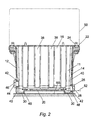
- Figure 2 is a cross-section, to an enlarged scale, taken on the line 2-2 of Figure 1.
- Referring to the drawings, one embodiment of the present invention is now described, by way of example only.
- A sump, generally designated 10, has the general form of an open-topped, rectangular box with a
peripheral wall 11 formed byside walls end walls floor 20. Atop flange 22 provides locations forfasteners 24 by which the sump is secured beneath the crankcase of anengine 50. It is to be understood that thesump 10 may also take the form of a closed box, such as an engine casing. The box may be a shape other than rectangular. Theperipheral wall 11 may be vertical or sloping and may include other arrangements of side walls and end walls. - On each of the
side walls sump 10 is provided with adrain aperture 28 which is shown closed by aremovable drain plug 26 and with an access opening 46 for an optional oil heater circuit which is shown closed by ablanking plug 44. The access opening 46 does not form part of the present invention, and may be omitted. - The
floor 20 is formed with agutter 30 adjacent a portion of the peripheral wall, in this embodiment with agutter 30 on either side adjacent thecorresponding side wall sump 10. Thefloor 20 is also formed (see Fig 1) to have a flatlowermost portion 32 in the vicinity of thedrain plugs 26 which is horizontal in use. On either side of thelowermost portion 32 are slopingportions lowermost portion 32. In the illustrated embodiment thelowermost portion 32 is arranged at the centre of thesump 10, but it is to be understood that it may be arranged at an off-centre position or adjacent to anend wall portion - The
gutters 30 in this embodiment have a cross-sectional shape which is shallow and approximately rectangular, but other shapes could be used, such as part-circular, trapezoidal or triangular. - The
drain plugs 26 are removably secured indrain apertures 28 formed by threadedinserts 42. Eachdrain aperture 28 is positioned to have at least its lowermost part 29 within therespective gutter 30. - The
sump 10 of this embodiment is moulded from reinforced plastics. Alternative materials may be used, such as cast iron or pressed sheet steel or aluminium alloy. Theside walls end walls stiffening ribs 38. Thegutters 30 assist in stiffening thefloor 20, and formsupport rails 48 adapted for resting on asupport surface 60 to carry the weight of anengine 50 to which thesump 10 is attached. - As seen in Figure 2, the thickness of the
side walls lower portions 40 in theside walls lowermost portion 32 of the floor. The thickenedportions 40 of theside walls drain apertures 28 andaccess openings 46. - The
drain plugs 26 andblanking plugs 44 are conventionally threaded plugs which screw into the threadedmetal inserts 42 which are secured in the thickenedwall portions 40. - Modifications to the foregoing embodiment may be made within the scope of the invention. For example, the
sump 10 may have agutter 30 on one side only, asingle drain aperture 28 may be provided, the drain aperture orapertures 28 need not be longitudinally central, and the sloping portions of the floor could be dispensed with so that in use thefloor 20 is horizontal and thegutter 30 is sloping or horizontal. One or more transverse gutters may connect thelongitudinal gutters 30. The gutter adjacent a portion of theperipheral wall 11 may be a transverse gutter extending across thefloor 20 of the sump at an intermediate location, with thedrain aperture 28 provided at the end of the transverse gutter. - When it is desired to drain oil from the
sump 10, one of thedrain plugs 26 is removed, thereby opening thedrain aperture 28. The oil in the sump is then free to flow out of thesump 10 through thedrain aperture 28. As the oil flows through thedrain aperture 28, the level of the oil in the sump falls. Because thegutters 30 are formed to be below theadjacent floor 20, as the oil level falls oil will tend to flow from thefloor 20 into the gutter orgutters 30. Oil then flows along the gutter orgutters 30 and then through thedrain aperture 28 until the oil level reaches the level of the lowermost part 29 of thedrain aperture 28, this level being indicated at 52 in Figure 2. At this point thesump 10 will contain only the small quantity of oil which remains belowlevel 44 in the gutter orgutters 30 in thelowermost portion 32 of the floor. The area of thefloor 20 between thegutters 30 will be free of oil. - It is to be understood that the
sloping portions floor 20 may be omitted. In this case after draining thesump 10 will contain only the small quantity of oil which remains belowlevel 44 along the complete length of the gutter. Since the cross sectional area of the gutter is small compared to the cross sectional area of the sump, this remaining quantity of oil is small compared to the quantity of oil in the sump before draining. Again, the area of thefloor 20 between thegutters 30 will be free of oil. - The thickened
portions 40 in theside walls side walls lowermost portion 32 of thefloor 20. This allows thegutters 30 in thelowermost portion 32 to be used assupport rails 48 to support the weight of anentire engine 50 when they rest temporarily on a supportingsurface 60, without risk of damage to theside walls - The present invention provides an improved sump which may be used with all kinds of internal combustion engines, or with any other mechanical apparatus in which fluid is circulated or stored and from which the fluid must be periodically drained, such as cooling or hydraulic fluid reservoirs. The improved sump allows good oil drainage in situations where access to the underside of the engine is not possible or not practical, with limited residual oil left in the sump. Cleaning of the sump is also facilitated.
Claims (14)
- A sump (10) for an internal combustion engine, comprising:a box having a peripheral wall (11) and a floor (20) ;the floor (20) being formed with at least one gutter (30) adjacent a portion of the peripheral wall (11); anda first closable drain aperture (28) located in the peripheral wall (11) with at least the lowermost part (29) of the drain aperture (28) located within said at least one gutter (30).
- A sump according to claim 1, including a drain plug (26) removably provided within the first drain aperture (28).
- A sump according to claim 1 or 2, wherein the peripheral wall (11) includes first and second side walls (12, 14) and the floor is formed with first and second gutters (30) adjacent the first and second side walls (12, 14) respectively.
- A sump according to claim 3, wherein the first drain aperture (28) is located within the first side wall (12) and a second closable drain aperture (28) is located in the second side wall (14) with at least the lowermost part (29) of the second drain aperture (28) located within said second gutter (30).
- A sump according to claim 3 or 4, wherein the gutters (30) form support rails (48) adapted for resting on a support surface (60).
- A sump according to any preceding claim, wherein the floor (20) and gutters (30) slope towards the location of the drain aperture (28).
- A sump according to any of claims 3 to 5, wherein the floor (20) has a lowermost portion (32) in which the floor and gutters (30) are horizontal in use; wherein the floor (20) has at least one sloping portion (34, 36) adjacent the lowermost portion (32) of the floor in which the floor and gutters (30) drain towards the lowermost portion (32) in use; and wherein each drain aperture (28) is located in a lower portion (40) of the respective side wall (12, 14) adjacent the lowermost portion (32) of the floor.
- A sump according to claim 7, wherein the side walls (12, 14) have an increased wall thickness locally in the area of the lower portions (40) of the side walls.
- An internal combustion engine (50) having a sump (10) in accordance with any preceding claim.
- A method for draining fluid from a sump (10) having a floor (20) and at least one closable drain aperture (28), the method comprising the steps of:opening the at least one drain aperture (28); andcausing fluid to flow within the sump along at least one gutter (30) formed in the floor of the sump and through the at least one drain aperture (28).
- A method according to claim 10, wherein the fluid flow step includes causing fluid to flow through at least a lowermost part (29) of the at least one drain aperture (28), said lowermost part (29) being located within said at least one gutter (30) .
- A method according to claim 10 or 11, wherein the sump (10) includes a peripheral wall (11) and the at least one drain aperture (28) is formed in the peripheral wall (11) of the sump, and wherein the fluid flow step includes causing fluid to flow within the sump along a gutter (30) located adjacent to a portion of the peripheral wall (11).
- A method according to claim 12, wherein said peripheral wall (11) includes first and second side walls (12, 14) and said sump includes first and second closable drain apertures (28) formed in the first and second side walls (12, 14) respectively, and wherein the fluid flow step includes causing fluid to flow within the sump along first and second gutters (30) located adjacent to the first and second side walls (12, 14) respectively.
- A method according to claim 10, wherein the sump floor (20) has a lowermost portion (32) in which the floor and the at least one gutter (30) are horizontal and at least one sloping portion (34, 36) adjacent the lowermost portion (32) of the floor in which the floor and the at least one gutter (30) drain towards the lowermost portion, and wherein the fluid flow step includes causing fluid to flow within the sump along the at least one gutter (30) to the lowermost portion (32) of the floor and then through the drain aperture (28).
Priority Applications (3)
| Application Number | Priority Date | Filing Date | Title |
|---|---|---|---|
| EP01308435A EP1300552B1 (en) | 2001-10-02 | 2001-10-02 | Fluid sump drainage |
| DE2001627840 DE60127840T2 (en) | 2001-10-02 | 2001-10-02 | Drainage device to the liquid container |
| US10/303,682 US20040099481A1 (en) | 2001-10-02 | 2002-11-25 | Fluid sump drainage |
Applications Claiming Priority (2)
| Application Number | Priority Date | Filing Date | Title |
|---|---|---|---|
| EP01308435A EP1300552B1 (en) | 2001-10-02 | 2001-10-02 | Fluid sump drainage |
| US10/303,682 US20040099481A1 (en) | 2001-10-02 | 2002-11-25 | Fluid sump drainage |
Publications (2)
| Publication Number | Publication Date |
|---|---|
| EP1300552A1 EP1300552A1 (en) | 2003-04-09 |
| EP1300552B1 true EP1300552B1 (en) | 2007-04-11 |
Family
ID=32870702
Family Applications (1)
| Application Number | Title | Priority Date | Filing Date |
|---|---|---|---|
| EP01308435A Expired - Lifetime EP1300552B1 (en) | 2001-10-02 | 2001-10-02 | Fluid sump drainage |
Country Status (2)
| Country | Link |
|---|---|
| US (1) | US20040099481A1 (en) |
| EP (1) | EP1300552B1 (en) |
Families Citing this family (1)
| Publication number | Priority date | Publication date | Assignee | Title |
|---|---|---|---|---|
| DE102020134074A1 (en) * | 2020-12-18 | 2022-06-23 | Bayerische Motoren Werke Aktiengesellschaft | Oil pan with oil drain plug |
Family Cites Families (18)
| Publication number | Priority date | Publication date | Assignee | Title |
|---|---|---|---|---|
| US1970754A (en) * | 1933-04-10 | 1934-08-21 | Jonasen Myers | Bed pad |
| US2187247A (en) * | 1939-01-25 | 1940-01-16 | Russell H Nichols | Crankcase drain valve |
| US2577188A (en) * | 1948-04-01 | 1951-12-04 | Michael F Hall | Composite oil pan for engines |
| US3120237A (en) * | 1961-03-15 | 1964-02-04 | Pure Oil Co | Crankcase spray device |
| US3189126A (en) * | 1963-03-18 | 1965-06-15 | Mack Trucks | Engine crankcase |
| US3310133A (en) * | 1964-05-20 | 1967-03-21 | Forrest D Eaker | Remote operated oil drain |
| US3653464A (en) * | 1970-04-13 | 1972-04-04 | Gen Motors Corp | Engine oil pan |
| US4084655A (en) * | 1975-08-15 | 1978-04-18 | Emil Savron | Motor vehicles |
| US4114644A (en) * | 1977-02-08 | 1978-09-19 | Piper Eldon L | Recycling drain pan |
| US4592443A (en) * | 1983-02-01 | 1986-06-03 | Jack Simon | Sobriety interlock |
| DE3831308C1 (en) * | 1988-09-15 | 1990-01-18 | Dr.Ing.H.C. F. Porsche Ag, 7000 Stuttgart, De | |
| JPH0763032A (en) * | 1993-08-27 | 1995-03-07 | Kubota Corp | Oil pan device for vehicle engine |
| FR2721976B1 (en) * | 1994-07-04 | 1996-08-30 | Renault | INTERNAL COMBUSTION ENGINE WITH IMPROVED OIL PAN AND HOUSING FOR SUCH AN ENGINE |
| US5482181A (en) * | 1995-03-20 | 1996-01-09 | Weaver; Donald L. | Portable liquid drain pan with cantilever extensions and pour spout |
| JP3360554B2 (en) * | 1996-11-26 | 2002-12-24 | スズキ株式会社 | Oil pan baffle plate structure |
| US5863424A (en) * | 1998-05-05 | 1999-01-26 | Dana Corporation | Filter element for oil pans and filter element/oil pan combination |
| JP2000337123A (en) * | 1999-05-24 | 2000-12-05 | Yamaha Motor Co Ltd | Engine equipment |
| US6378639B1 (en) * | 2000-09-15 | 2002-04-30 | Patrick W. Murray | Oil drip pan assembly for a vehicle |
-
2001
- 2001-10-02 EP EP01308435A patent/EP1300552B1/en not_active Expired - Lifetime
-
2002
- 2002-11-25 US US10/303,682 patent/US20040099481A1/en not_active Abandoned
Also Published As
| Publication number | Publication date |
|---|---|
| EP1300552A1 (en) | 2003-04-09 |
| US20040099481A1 (en) | 2004-05-27 |
Similar Documents
| Publication | Publication Date | Title |
|---|---|---|
| US8776757B2 (en) | Transmission fluid pan | |
| US6237720B1 (en) | Engine oil pan including sediment basin and baffle configuration | |
| US6982379B2 (en) | Automotive electrical connection box and a method of mounting it | |
| EP1300552B1 (en) | Fluid sump drainage | |
| GB2538318A (en) | A sump | |
| US6520164B1 (en) | Crankcase ventilation oil drain tube | |
| EP1550814B1 (en) | Bearing housing with divided drainage and oil pooling annulus | |
| DE60127840T2 (en) | Drainage device to the liquid container | |
| CN214464475U (en) | Concave-convex oil collecting disc of marine diesel filter | |
| CN2448429Y (en) | Oil and water separator | |
| CN206707797U (en) | Sump for internal combustion engine | |
| EP2184516B1 (en) | Vehicle sump | |
| JP3713398B2 (en) | Grease interception method inside railway viaduct | |
| JPS59396Y2 (en) | Grease trap | |
| EP1514620B1 (en) | Engine block | |
| JPS643449Y2 (en) | ||
| JPS6214322Y2 (en) | ||
| CN207739357U (en) | A kind of underground garage oil removal catch-basin | |
| TH67087A (en) | engine | |
| JPH06336952A (en) | Oil pan | |
| JPS61119586A (en) | Oil collector for escalator or moving sidewalk | |
| CN209735100U (en) | Mechanism is collected to pressure filter drainage | |
| RU2227787C1 (en) | Plant for percolation leaching of aluminum- containing ores and sinters | |
| CA2896802C (en) | Grease interceptor system and method of installing a grease interceptor system | |
| JPS5839717B2 (en) | Emergency drain for floating roof tank |
Legal Events
| Date | Code | Title | Description |
|---|---|---|---|
| PUAI | Public reference made under article 153(3) epc to a published international application that has entered the european phase |
Free format text: ORIGINAL CODE: 0009012 |
|
| AK | Designated contracting states |
Kind code of ref document: A1 Designated state(s): AT BE CH CY DE DK ES FI FR GB GR IE IT LI LU MC NL PT SE TR |
|
| AX | Request for extension of the european patent |
Extension state: AL LT LV MK RO SI |
|
| 17P | Request for examination filed |
Effective date: 20030912 |
|
| AKX | Designation fees paid |
Designated state(s): DE FR GB |
|
| RBV | Designated contracting states (corrected) |
Designated state(s): DE FR GB |
|
| GRAP | Despatch of communication of intention to grant a patent |
Free format text: ORIGINAL CODE: EPIDOSNIGR1 |
|
| GRAS | Grant fee paid |
Free format text: ORIGINAL CODE: EPIDOSNIGR3 |
|
| GRAA | (expected) grant |
Free format text: ORIGINAL CODE: 0009210 |
|
| RAP1 | Party data changed (applicant data changed or rights of an application transferred) |
Owner name: PERKINS ENGINES COMPANY LIMITED |
|
| AK | Designated contracting states |
Kind code of ref document: B1 Designated state(s): DE FR GB |
|
| REG | Reference to a national code |
Ref country code: GB Ref legal event code: FG4D |
|
| REF | Corresponds to: |
Ref document number: 60127840 Country of ref document: DE Date of ref document: 20070524 Kind code of ref document: P |
|
| EN | Fr: translation not filed | ||
| PLBE | No opposition filed within time limit |
Free format text: ORIGINAL CODE: 0009261 |
|
| STAA | Information on the status of an ep patent application or granted ep patent |
Free format text: STATUS: NO OPPOSITION FILED WITHIN TIME LIMIT |
|
| 26N | No opposition filed |
Effective date: 20080114 |
|
| PG25 | Lapsed in a contracting state [announced via postgrant information from national office to epo] |
Ref country code: FR Free format text: LAPSE BECAUSE OF FAILURE TO SUBMIT A TRANSLATION OF THE DESCRIPTION OR TO PAY THE FEE WITHIN THE PRESCRIBED TIME-LIMIT Effective date: 20071207 |
|
| PG25 | Lapsed in a contracting state [announced via postgrant information from national office to epo] |
Ref country code: FR Free format text: LAPSE BECAUSE OF FAILURE TO SUBMIT A TRANSLATION OF THE DESCRIPTION OR TO PAY THE FEE WITHIN THE PRESCRIBED TIME-LIMIT Effective date: 20070411 |
|
| PGFP | Annual fee paid to national office [announced via postgrant information from national office to epo] |
Ref country code: DE Payment date: 20121031 Year of fee payment: 12 |
|
| REG | Reference to a national code |
Ref country code: DE Ref legal event code: R119 Ref document number: 60127840 Country of ref document: DE Effective date: 20140501 |
|
| PG25 | Lapsed in a contracting state [announced via postgrant information from national office to epo] |
Ref country code: DE Free format text: LAPSE BECAUSE OF NON-PAYMENT OF DUE FEES Effective date: 20140501 |
|
| PGFP | Annual fee paid to national office [announced via postgrant information from national office to epo] |
Ref country code: GB Payment date: 20160926 Year of fee payment: 16 |
|
| GBPC | Gb: european patent ceased through non-payment of renewal fee |
Effective date: 20171002 |
|
| PG25 | Lapsed in a contracting state [announced via postgrant information from national office to epo] |
Ref country code: GB Free format text: LAPSE BECAUSE OF NON-PAYMENT OF DUE FEES Effective date: 20171002 |