EP1300326A2 - Dispositif de fixation pour pièces de carrosserie automobile - Google Patents
Dispositif de fixation pour pièces de carrosserie automobile Download PDFInfo
- Publication number
- EP1300326A2 EP1300326A2 EP02019517A EP02019517A EP1300326A2 EP 1300326 A2 EP1300326 A2 EP 1300326A2 EP 02019517 A EP02019517 A EP 02019517A EP 02019517 A EP02019517 A EP 02019517A EP 1300326 A2 EP1300326 A2 EP 1300326A2
- Authority
- EP
- European Patent Office
- Prior art keywords
- channel
- support
- guide rail
- side part
- edge
- Prior art date
- Legal status (The legal status is an assumption and is not a legal conclusion. Google has not performed a legal analysis and makes no representation as to the accuracy of the status listed.)
- Granted
Links
Images


Classifications
-
- B—PERFORMING OPERATIONS; TRANSPORTING
- B62—LAND VEHICLES FOR TRAVELLING OTHERWISE THAN ON RAILS
- B62D—MOTOR VEHICLES; TRAILERS
- B62D25/00—Superstructure or monocoque structure sub-units; Parts or details thereof not otherwise provided for
- B62D25/08—Front or rear portions
- B62D25/16—Mud-guards or wings; Wheel cover panels
- B62D25/163—Mounting devices
-
- B—PERFORMING OPERATIONS; TRANSPORTING
- B60—VEHICLES IN GENERAL
- B60R—VEHICLES, VEHICLE FITTINGS, OR VEHICLE PARTS, NOT OTHERWISE PROVIDED FOR
- B60R19/00—Wheel guards; Radiator guards, e.g. grilles; Obstruction removers; Fittings damping bouncing force in collisions
- B60R19/02—Bumpers, i.e. impact receiving or absorbing members for protecting vehicles or fending off blows from other vehicles or objects
- B60R19/24—Arrangements for mounting bumpers on vehicles
- B60R2019/247—Fastening of bumpers' side ends
Definitions
- the invention relates to a device for fixing body parts, in particular a rear trim part according to the preamble of claim 1.
- the object of the invention is to provide a device for fixing body parts, in particular a rear trim part on a guide rail of a side part create with which it is easily possible to create a defined and lasting To ensure gap between the side part and the rear trim part.
- the main advantages achieved with the invention are that by means of a a precisely positionable guide rail on the respective side part of the vehicle Rear trim part can be mounted with a so-called zero joint.
- first channel-like support in each case in an outward direction of the Vehicle-directed approximately horizontal section of a side part first channel-like support is provided, which in at least one area has branching, downwardly directed second channel-like support.
- second channel-like support In both Support is the guide rail with corresponding channel-like Expressions kept in position.
- the first channel-like support is on an edge region of the side part arranged in a vertical plane and U-shaped in cross section. On this edge region of the side part closes a mounting plate for one Bumper in which the second channel-like support is partially arranged. Consequently the rear panel can be connected to the Edge of the side panel to be attached, with the downward facing second Support by the extension in the bracket for the bumper one Secured fixation of the guide rail in the X direction guaranteed.
- Both the characteristics of the guide rail and the channel-like supports are U-shaped, so that a positive reception of the Guide rail is guaranteed in the channel-like supports.
- the guide rail preferably has an oblong U-shaped cross section Expression, which is arranged in the first channel-like support.
- the leg of the shape is the guide rail on a side wall of the channel-like Support positioned in the Z direction.
- the guide rail on the side wall of the channel-like support is also the Position the rear panel exactly to the side part and it will be a stable one Fixed to the side part achieved.
- the second branching channel-like support in the edge of the side part and in the edge of the mounting plate has an embossing in which the guide rail with an expression in the X direction is held. Since the side part ends up one after has rounded bottom, can via the second channel-like support Achieve the rear trim part on the side part achieved with a so-called zero joint become.
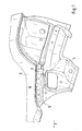
- the device for fixing body parts in particular one Rear trim part 1 on a side part 1 on a side part 2 of a motor vehicle essentially comprises a guide rail 3 which with the side part 2 and one with this connected bracket plate 4 is designed for a bumper.
- a mounting plate 4 On a lower connecting edge 5 of the side part 2 there is a mounting plate 4 attached and the side part 2 has a channel-like approximately horizontally extending first Support 6 on which in the rear section a downward second channel-like Has support 7, which extends partially into the mounting plate 4.
- This channel-like supports 6 and 7 consist of impressions and are in cross section U-shaped.
- the guide profile 3 is used, the corresponding to these supports 6, 7 also in cross section from a Characterization in the form of a U-profile 6a and in the rear area a downward has directed recess 7a corresponding to the support 7.
- the guide rail 3 has 1 leg or for receiving the rear trim part Tabs 10, 11 between which an edge of the rear trim part 1 in Arrow direction A is inserted and attached to the guide rail 3.
- the guide rail 3 is in the channel-like support 6 via screwing means 13 attached so that a stable position is guaranteed.
- a support for the Guide rail 3 in the Z direction takes place on the side wall 14 of the channel-like Support 6.
- the guide rail 3 is held in the downward direction Support 7 on the corresponding side wall parts.
- the side part 2 has an end 17 facing the wheel cutout 16 downward fillet 18; the guide rail 3 is also corresponding executed. Through the downward guide rail 3 in this area is inevitably a close concern of the support 7 Rear trim part 1 achieved on the side part 2.
- the guide profile 3 preferably extends from the rounded end 17 of the Side part 2 to the rear end 19 of the side part 2 or the mounting plate 4, the channel-like support 6 in the side part 2 being limited Area B extends. In the further area C of the side part 2 or Bracket 4 is the guide rail 3 with the bracket 4 directly connected without channel-like support.
Landscapes
- Engineering & Computer Science (AREA)
- Mechanical Engineering (AREA)
- Chemical & Material Sciences (AREA)
- Combustion & Propulsion (AREA)
- Transportation (AREA)
- Body Structure For Vehicles (AREA)
- Vehicle Interior And Exterior Ornaments, Soundproofing, And Insulation (AREA)
- Lighting Device Outwards From Vehicle And Optical Signal (AREA)
- Connection Of Plates (AREA)
Applications Claiming Priority (2)
| Application Number | Priority Date | Filing Date | Title |
|---|---|---|---|
| DE10149003A DE10149003B4 (de) | 2001-10-04 | 2001-10-04 | Vorrichtung zum Fixieren von Karosserieteilen |
| DE10149003 | 2001-10-04 |
Publications (3)
| Publication Number | Publication Date |
|---|---|
| EP1300326A2 true EP1300326A2 (fr) | 2003-04-09 |
| EP1300326A3 EP1300326A3 (fr) | 2003-08-20 |
| EP1300326B1 EP1300326B1 (fr) | 2004-11-03 |
Family
ID=7701395
Family Applications (1)
| Application Number | Title | Priority Date | Filing Date |
|---|---|---|---|
| EP02019517A Expired - Lifetime EP1300326B1 (fr) | 2001-10-04 | 2002-08-31 | Dispositif de fixation pour pièces de carrosserie automobile |
Country Status (6)
| Country | Link |
|---|---|
| US (1) | US6688675B2 (fr) |
| EP (1) | EP1300326B1 (fr) |
| JP (1) | JP3742787B2 (fr) |
| AT (1) | ATE281341T1 (fr) |
| DE (2) | DE10149003B4 (fr) |
| ES (1) | ES2229038T3 (fr) |
Cited By (3)
| Publication number | Priority date | Publication date | Assignee | Title |
|---|---|---|---|---|
| FR2922838A1 (fr) * | 2007-10-26 | 2009-05-01 | Peugeot Citroen Automobiles Sa | Dispositif de fixation d'un pare-chocs arriere sur l'aile arriere d'un vehicule |
| FR2951675A1 (fr) * | 2009-10-28 | 2011-04-29 | Peugeot Citroen Automobiles Sa | Partie arriere de vehicule automobile comprenant deux feux arrieres et des supports pour soutenir le pare-choc |
| CN112550198A (zh) * | 2020-12-23 | 2021-03-26 | 东风小康汽车有限公司重庆分公司 | 一体式后保支架 |
Families Citing this family (3)
| Publication number | Priority date | Publication date | Assignee | Title |
|---|---|---|---|---|
| US7445259B1 (en) | 2007-06-08 | 2008-11-04 | Ford Global Technologies, Llc | Fascia anti-rattle springs |
| DE102010020888B4 (de) | 2010-05-18 | 2022-09-01 | Volkswagen Ag | Verfahren und Anordnung zur Befestigung eines Montageteils eines Fahrzeugs an einem Karosserieteil des Fahrzeugs sowie Halteteil dazu |
| DE102021132489A1 (de) | 2021-12-09 | 2023-06-15 | Bayerische Motoren Werke Aktiengesellschaft | Befestigungsanordnung und Verfahren zur Befestigung eines Bauelements mittels einer derartigen Befestigungsanordnung |
Citations (1)
| Publication number | Priority date | Publication date | Assignee | Title |
|---|---|---|---|---|
| DE19741062A1 (de) | 1997-09-18 | 1999-04-01 | Rehau Ag & Co | Mehrfunktionsschiene |
Family Cites Families (18)
| Publication number | Priority date | Publication date | Assignee | Title |
|---|---|---|---|---|
| JPS5718540A (en) * | 1980-07-07 | 1982-01-30 | Mazda Motor Corp | Bumper-side fixing structure of automobile |
| JPS5718541A (en) * | 1980-07-09 | 1982-01-30 | Nissan Motor Co Ltd | Rear bumper structure of automobile |
| JPS59184066A (ja) * | 1983-03-31 | 1984-10-19 | Nissan Motor Co Ltd | 自動車の後側部構造 |
| JPS604443A (ja) * | 1983-06-23 | 1985-01-10 | Nissan Motor Co Ltd | バンパ−サイドの取付構造 |
| JPS6437754U (fr) * | 1987-09-01 | 1989-03-07 | ||
| US4895406A (en) * | 1988-02-12 | 1990-01-23 | Dr. Ing. H.C.F. Porsche Ag | Bumper arrangement with an adjustable covering for motor vehicles |
| JP2717970B2 (ja) * | 1988-07-28 | 1998-02-25 | スズキ株式会社 | 車体後部構造 |
| US4875728A (en) * | 1988-09-16 | 1989-10-24 | Chrysler Motors Corporation | Bumper facia attachment structure |
| JP2563612B2 (ja) * | 1989-10-20 | 1996-12-11 | 日産自動車株式会社 | バンパフェイシアの取付構造 |
| US5061108A (en) * | 1990-12-24 | 1991-10-29 | Chrysler Corporation | Attaching arrangement for vehicle plastic panel |
| DE4432764A1 (de) * | 1994-09-14 | 1996-03-21 | Braun Pebra Gmbh | Stoßfänger |
| FR2728846A1 (fr) * | 1995-01-03 | 1996-07-05 | Plastic Omnium Cie | Dispositif pour le positionnement precis d'une piece de carrosserie de vehicule sur un support, notamment une autre piece de carrosserie |
| DE19620404C1 (de) * | 1996-05-21 | 1997-08-14 | Porsche Ag | Verkleidungsteil aus nachgiebigem Werkstoff für einen Endbereich eines Fahrzeuges, insbesondere Personenkraftwagen |
| JP3319298B2 (ja) * | 1996-08-27 | 2002-08-26 | 三菱自動車工業株式会社 | バンパフェースの構造 |
| DE10114018B4 (de) * | 2001-03-22 | 2005-05-25 | Dr.Ing.H.C. F. Porsche Ag | Aufnahme- und Verbindungsvorrichtung für eine Bug/Heckschürze eines Kraftfahrzeugs |
| FR2823804B1 (fr) * | 2001-04-19 | 2004-03-26 | Plastic Omnium Cie | Ensemble de deux pieces de carrosserie a reunir bord a bord et piece de carosserie appartenant a un tel ensemble |
| FR2823805B1 (fr) * | 2001-04-19 | 2004-03-12 | Plastic Omnium Cie | Ensemble de deux pieces de carrosserie a reunir bord a bord et une piece de carrosserie appartenant a un tel ensemble |
| JP4806495B2 (ja) * | 2001-06-06 | 2011-11-02 | 水菱プラスチック株式会社 | 車両用外装部材の取付構造 |
-
2001
- 2001-10-04 DE DE10149003A patent/DE10149003B4/de not_active Expired - Fee Related
-
2002
- 2002-08-31 DE DE50201450T patent/DE50201450D1/de not_active Expired - Lifetime
- 2002-08-31 ES ES02019517T patent/ES2229038T3/es not_active Expired - Lifetime
- 2002-08-31 EP EP02019517A patent/EP1300326B1/fr not_active Expired - Lifetime
- 2002-08-31 AT AT02019517T patent/ATE281341T1/de not_active IP Right Cessation
- 2002-10-02 JP JP2002290292A patent/JP3742787B2/ja not_active Expired - Fee Related
- 2002-10-04 US US10/263,776 patent/US6688675B2/en not_active Expired - Lifetime
Patent Citations (1)
| Publication number | Priority date | Publication date | Assignee | Title |
|---|---|---|---|---|
| DE19741062A1 (de) | 1997-09-18 | 1999-04-01 | Rehau Ag & Co | Mehrfunktionsschiene |
Cited By (3)
| Publication number | Priority date | Publication date | Assignee | Title |
|---|---|---|---|---|
| FR2922838A1 (fr) * | 2007-10-26 | 2009-05-01 | Peugeot Citroen Automobiles Sa | Dispositif de fixation d'un pare-chocs arriere sur l'aile arriere d'un vehicule |
| FR2951675A1 (fr) * | 2009-10-28 | 2011-04-29 | Peugeot Citroen Automobiles Sa | Partie arriere de vehicule automobile comprenant deux feux arrieres et des supports pour soutenir le pare-choc |
| CN112550198A (zh) * | 2020-12-23 | 2021-03-26 | 东风小康汽车有限公司重庆分公司 | 一体式后保支架 |
Also Published As
| Publication number | Publication date |
|---|---|
| US6688675B2 (en) | 2004-02-10 |
| EP1300326A3 (fr) | 2003-08-20 |
| DE50201450D1 (de) | 2004-12-09 |
| DE10149003A1 (de) | 2003-04-24 |
| ES2229038T3 (es) | 2005-04-16 |
| JP3742787B2 (ja) | 2006-02-08 |
| JP2003118645A (ja) | 2003-04-23 |
| DE10149003B4 (de) | 2004-06-17 |
| ATE281341T1 (de) | 2004-11-15 |
| EP1300326B1 (fr) | 2004-11-03 |
| US20030080584A1 (en) | 2003-05-01 |
Similar Documents
| Publication | Publication Date | Title |
|---|---|---|
| EP1059221B1 (fr) | Traverse de renfort de tableau de bord pour véhicule automobile | |
| DE10114018B4 (de) | Aufnahme- und Verbindungsvorrichtung für eine Bug/Heckschürze eines Kraftfahrzeugs | |
| EP1780086B1 (fr) | Dispositif pour fixer en position exacte un pare-chocs | |
| DE102006012176A1 (de) | Einstellbarer Fensterheber I | |
| EP0786398A1 (fr) | Structure d'une carrosserie d'un véhicule à moteur et gabarit de montage | |
| EP1912827B1 (fr) | Dispositif de fixation reglable d'un phare | |
| WO2013120894A1 (fr) | Tiroir | |
| DE10203055A1 (de) | Fußstütze für ein Fahrzeug | |
| EP1400707B1 (fr) | Raccordement démontable entre deux composants adjacents, en particulier panneaux externes d'un corps de véhicule | |
| DE19741062A1 (de) | Mehrfunktionsschiene | |
| DE102012008832A1 (de) | Vorbaustruktur eines Kraftfahrzeugs | |
| DE19735818A1 (de) | Befestigungsvorrichtung für eine Scheibenwischeranlage eines Kraftfahrzeuges | |
| EP1300326B1 (fr) | Dispositif de fixation pour pièces de carrosserie automobile | |
| EP1253045A1 (fr) | Dispositif d'attache pour un élément de montage à une structure de carrosserie de véhicule automobile | |
| EP1775173A2 (fr) | Dispositif pour la fixation d'un capteur | |
| EP2730457A1 (fr) | Entraînement d'un dispositif de réglage de siège pour véhicules automobiles | |
| DE3301413C2 (de) | Vorrichtung zur Befestigung eines Dachgepäckträgers , Skihalters od. dgl. auf einem Fahrzeugdach | |
| DE10248169B4 (de) | Vorrichtung zum lagegenauen Einbau eines Montageträgers für eine Schalttafel in ein Kraftfahrzeug | |
| EP1600338A1 (fr) | Véhicule avec un élément déformable absorbeur d'énergie | |
| DE102012023785A1 (de) | Vorrichtung zum spannungsarmen Verbinden zweier Bauteile eines Kraftfahrzeuges sowie Fahrzeug-Scheinwerfer | |
| DE102010051357A1 (de) | Halteanordnung für einen Stoßfänger und Verfahren zum Montieren eines Stoßfängers | |
| DE4426155A1 (de) | Kraftfahrzeug, insbesondere Personenkraftwagen | |
| DE10100333A1 (de) | Fahrzeugkarosserie- und Rahmenanordnung | |
| DE10346893A1 (de) | Verbindungsanordnung im Vorderwagen eines Kraftfahrzeugs | |
| WO2019030369A1 (fr) | Dispositif de réglage longitudinal d'un siège de véhicule |
Legal Events
| Date | Code | Title | Description |
|---|---|---|---|
| PUAI | Public reference made under article 153(3) epc to a published international application that has entered the european phase |
Free format text: ORIGINAL CODE: 0009012 |
|
| AK | Designated contracting states |
Kind code of ref document: A2 Designated state(s): AT BE BG CH CY CZ DE DK EE ES FI FR GB GR IE IT LI LU MC NL PT SE SK TR |
|
| AX | Request for extension of the european patent |
Extension state: AL LT LV MK RO SI |
|
| PUAL | Search report despatched |
Free format text: ORIGINAL CODE: 0009013 |
|
| AK | Designated contracting states |
Designated state(s): AT BE BG CH CY CZ DE DK EE ES FI FR GB GR IE IT LI LU MC NL PT SE SK TR |
|
| AX | Request for extension of the european patent |
Extension state: AL LT LV MK RO SI |
|
| 17P | Request for examination filed |
Effective date: 20040220 |
|
| GRAP | Despatch of communication of intention to grant a patent |
Free format text: ORIGINAL CODE: EPIDOSNIGR1 |
|
| AKX | Designation fees paid |
Designated state(s): AT DE ES FR GB IT |
|
| GRAS | Grant fee paid |
Free format text: ORIGINAL CODE: EPIDOSNIGR3 |
|
| GRAA | (expected) grant |
Free format text: ORIGINAL CODE: 0009210 |
|
| AK | Designated contracting states |
Kind code of ref document: B1 Designated state(s): AT DE ES FR GB IT |
|
| REG | Reference to a national code |
Ref country code: GB Ref legal event code: FG4D Free format text: NOT ENGLISH |
|
| REF | Corresponds to: |
Ref document number: 50201450 Country of ref document: DE Date of ref document: 20041209 Kind code of ref document: P |
|
| REG | Reference to a national code |
Ref country code: IE Ref legal event code: FG4D Free format text: GERMAN |
|
| GBT | Gb: translation of ep patent filed (gb section 77(6)(a)/1977) |
Effective date: 20050303 |
|
| REG | Reference to a national code |
Ref country code: ES Ref legal event code: FG2A Ref document number: 2229038 Country of ref document: ES Kind code of ref document: T3 |
|
| REG | Reference to a national code |
Ref country code: IE Ref legal event code: FD4D |
|
| ET | Fr: translation filed | ||
| PLBE | No opposition filed within time limit |
Free format text: ORIGINAL CODE: 0009261 |
|
| STAA | Information on the status of an ep patent application or granted ep patent |
Free format text: STATUS: NO OPPOSITION FILED WITHIN TIME LIMIT |
|
| 26N | No opposition filed |
Effective date: 20050804 |
|
| PGFP | Annual fee paid to national office [announced via postgrant information from national office to epo] |
Ref country code: ES Payment date: 20070830 Year of fee payment: 6 |
|
| PGFP | Annual fee paid to national office [announced via postgrant information from national office to epo] |
Ref country code: AT Payment date: 20070816 Year of fee payment: 6 |
|
| PG25 | Lapsed in a contracting state [announced via postgrant information from national office to epo] |
Ref country code: AT Free format text: LAPSE BECAUSE OF NON-PAYMENT OF DUE FEES Effective date: 20080831 |
|
| REG | Reference to a national code |
Ref country code: FR Ref legal event code: TP |
|
| REG | Reference to a national code |
Ref country code: ES Ref legal event code: FD2A Effective date: 20080901 |
|
| REG | Reference to a national code |
Ref country code: FR Ref legal event code: CD |
|
| PG25 | Lapsed in a contracting state [announced via postgrant information from national office to epo] |
Ref country code: ES Free format text: LAPSE BECAUSE OF NON-PAYMENT OF DUE FEES Effective date: 20080901 |
|
| REG | Reference to a national code |
Ref country code: FR Ref legal event code: TP |
|
| REG | Reference to a national code |
Ref country code: GB Ref legal event code: 732E Free format text: REGISTERED BETWEEN 20110310 AND 20110316 |
|
| REG | Reference to a national code |
Ref country code: GB Ref legal event code: 732E Free format text: REGISTERED BETWEEN 20110331 AND 20110406 |
|
| REG | Reference to a national code |
Ref country code: FR Ref legal event code: PLFP Year of fee payment: 15 |
|
| PGFP | Annual fee paid to national office [announced via postgrant information from national office to epo] |
Ref country code: IT Payment date: 20160825 Year of fee payment: 15 Ref country code: GB Payment date: 20160819 Year of fee payment: 15 |
|
| PGFP | Annual fee paid to national office [announced via postgrant information from national office to epo] |
Ref country code: FR Payment date: 20160822 Year of fee payment: 15 |
|
| GBPC | Gb: european patent ceased through non-payment of renewal fee |
Effective date: 20170831 |
|
| REG | Reference to a national code |
Ref country code: FR Ref legal event code: ST Effective date: 20180430 |
|
| PG25 | Lapsed in a contracting state [announced via postgrant information from national office to epo] |
Ref country code: GB Free format text: LAPSE BECAUSE OF NON-PAYMENT OF DUE FEES Effective date: 20170831 |
|
| PG25 | Lapsed in a contracting state [announced via postgrant information from national office to epo] |
Ref country code: FR Free format text: LAPSE BECAUSE OF NON-PAYMENT OF DUE FEES Effective date: 20170831 Ref country code: IT Free format text: LAPSE BECAUSE OF NON-PAYMENT OF DUE FEES Effective date: 20170831 |
|
| PGFP | Annual fee paid to national office [announced via postgrant information from national office to epo] |
Ref country code: DE Payment date: 20180827 Year of fee payment: 17 |
|
| REG | Reference to a national code |
Ref country code: DE Ref legal event code: R119 Ref document number: 50201450 Country of ref document: DE |
|
| PG25 | Lapsed in a contracting state [announced via postgrant information from national office to epo] |
Ref country code: DE Free format text: LAPSE BECAUSE OF NON-PAYMENT OF DUE FEES Effective date: 20200303 |