EP1298331A2 - Vis-cheville - Google Patents
Vis-cheville Download PDFInfo
- Publication number
- EP1298331A2 EP1298331A2 EP02405755A EP02405755A EP1298331A2 EP 1298331 A2 EP1298331 A2 EP 1298331A2 EP 02405755 A EP02405755 A EP 02405755A EP 02405755 A EP02405755 A EP 02405755A EP 1298331 A2 EP1298331 A2 EP 1298331A2
- Authority
- EP
- European Patent Office
- Prior art keywords
- screw
- plug
- anchor
- engagement
- flange
- Prior art date
- Legal status (The legal status is an assumption and is not a legal conclusion. Google has not performed a legal analysis and makes no representation as to the accuracy of the status listed.)
- Granted
Links
- 238000005553 drilling Methods 0.000 claims description 12
- 230000008878 coupling Effects 0.000 claims description 10
- 238000010168 coupling process Methods 0.000 claims description 10
- 238000005859 coupling reaction Methods 0.000 claims description 10
- 239000003562 lightweight material Substances 0.000 claims description 3
- 238000000926 separation method Methods 0.000 claims description 3
- 230000002093 peripheral effect Effects 0.000 claims 1
- 239000004035 construction material Substances 0.000 description 6
- 238000004873 anchoring Methods 0.000 description 5
- 239000004566 building material Substances 0.000 description 4
- 238000010276 construction Methods 0.000 description 2
- 230000035515 penetration Effects 0.000 description 2
- 238000010521 absorption reaction Methods 0.000 description 1
- 230000001419 dependent effect Effects 0.000 description 1
- 239000000428 dust Substances 0.000 description 1
- 239000012634 fragment Substances 0.000 description 1
- 238000003780 insertion Methods 0.000 description 1
- 230000037431 insertion Effects 0.000 description 1
- 230000036346 tooth eruption Effects 0.000 description 1
Images


Classifications
-
- B—PERFORMING OPERATIONS; TRANSPORTING
- B25—HAND TOOLS; PORTABLE POWER-DRIVEN TOOLS; MANIPULATORS
- B25B—TOOLS OR BENCH DEVICES NOT OTHERWISE PROVIDED FOR, FOR FASTENING, CONNECTING, DISENGAGING OR HOLDING
- B25B15/00—Screwdrivers
- B25B15/001—Screwdrivers characterised by material or shape of the tool bit
- B25B15/004—Screwdrivers characterised by material or shape of the tool bit characterised by cross-section
- B25B15/005—Screwdrivers characterised by material or shape of the tool bit characterised by cross-section with cross- or star-shaped cross-section
-
- F—MECHANICAL ENGINEERING; LIGHTING; HEATING; WEAPONS; BLASTING
- F16—ENGINEERING ELEMENTS AND UNITS; GENERAL MEASURES FOR PRODUCING AND MAINTAINING EFFECTIVE FUNCTIONING OF MACHINES OR INSTALLATIONS; THERMAL INSULATION IN GENERAL
- F16B—DEVICES FOR FASTENING OR SECURING CONSTRUCTIONAL ELEMENTS OR MACHINE PARTS TOGETHER, e.g. NAILS, BOLTS, CIRCLIPS, CLAMPS, CLIPS OR WEDGES; JOINTS OR JOINTING
- F16B13/00—Dowels or other devices fastened in walls or the like by inserting them in holes made therein for that purpose
- F16B13/002—Dowels or other devices fastened in walls or the like by inserting them in holes made therein for that purpose self-cutting
-
- F—MECHANICAL ENGINEERING; LIGHTING; HEATING; WEAPONS; BLASTING
- F16—ENGINEERING ELEMENTS AND UNITS; GENERAL MEASURES FOR PRODUCING AND MAINTAINING EFFECTIVE FUNCTIONING OF MACHINES OR INSTALLATIONS; THERMAL INSULATION IN GENERAL
- F16B—DEVICES FOR FASTENING OR SECURING CONSTRUCTIONAL ELEMENTS OR MACHINE PARTS TOGETHER, e.g. NAILS, BOLTS, CIRCLIPS, CLAMPS, CLIPS OR WEDGES; JOINTS OR JOINTING
- F16B13/00—Dowels or other devices fastened in walls or the like by inserting them in holes made therein for that purpose
- F16B13/02—Dowels or other devices fastened in walls or the like by inserting them in holes made therein for that purpose in one piece with protrusions or ridges on the shaft
-
- F—MECHANICAL ENGINEERING; LIGHTING; HEATING; WEAPONS; BLASTING
- F16—ENGINEERING ELEMENTS AND UNITS; GENERAL MEASURES FOR PRODUCING AND MAINTAINING EFFECTIVE FUNCTIONING OF MACHINES OR INSTALLATIONS; THERMAL INSULATION IN GENERAL
- F16B—DEVICES FOR FASTENING OR SECURING CONSTRUCTIONAL ELEMENTS OR MACHINE PARTS TOGETHER, e.g. NAILS, BOLTS, CIRCLIPS, CLAMPS, CLIPS OR WEDGES; JOINTS OR JOINTING
- F16B13/00—Dowels or other devices fastened in walls or the like by inserting them in holes made therein for that purpose
- F16B13/12—Separate metal or non-separate or non-metal dowel sleeves fastened by inserting the screw, nail or the like
- F16B13/128—Separate metal or non-separate or non-metal dowel sleeves fastened by inserting the screw, nail or the like with extending protrusions, e.g. discs, segments, ridges, fingers or tongues
-
- F—MECHANICAL ENGINEERING; LIGHTING; HEATING; WEAPONS; BLASTING
- F16—ENGINEERING ELEMENTS AND UNITS; GENERAL MEASURES FOR PRODUCING AND MAINTAINING EFFECTIVE FUNCTIONING OF MACHINES OR INSTALLATIONS; THERMAL INSULATION IN GENERAL
- F16B—DEVICES FOR FASTENING OR SECURING CONSTRUCTIONAL ELEMENTS OR MACHINE PARTS TOGETHER, e.g. NAILS, BOLTS, CIRCLIPS, CLAMPS, CLIPS OR WEDGES; JOINTS OR JOINTING
- F16B23/00—Specially shaped nuts or heads of bolts or screws for rotations by a tool
- F16B23/0007—Specially shaped nuts or heads of bolts or screws for rotations by a tool characterised by the shape of the recess or the protrusion engaging the tool
- F16B23/003—Specially shaped nuts or heads of bolts or screws for rotations by a tool characterised by the shape of the recess or the protrusion engaging the tool star-shaped or multi-lobular, e.g. Torx-type, twelve-point star
-
- F—MECHANICAL ENGINEERING; LIGHTING; HEATING; WEAPONS; BLASTING
- F16—ENGINEERING ELEMENTS AND UNITS; GENERAL MEASURES FOR PRODUCING AND MAINTAINING EFFECTIVE FUNCTIONING OF MACHINES OR INSTALLATIONS; THERMAL INSULATION IN GENERAL
- F16B—DEVICES FOR FASTENING OR SECURING CONSTRUCTIONAL ELEMENTS OR MACHINE PARTS TOGETHER, e.g. NAILS, BOLTS, CIRCLIPS, CLAMPS, CLIPS OR WEDGES; JOINTS OR JOINTING
- F16B23/00—Specially shaped nuts or heads of bolts or screws for rotations by a tool
- F16B23/0007—Specially shaped nuts or heads of bolts or screws for rotations by a tool characterised by the shape of the recess or the protrusion engaging the tool
- F16B23/0038—Specially shaped nuts or heads of bolts or screws for rotations by a tool characterised by the shape of the recess or the protrusion engaging the tool substantially prismatic with up to six edges, e.g. triangular, square, pentagonal, Allen-type cross-sections
-
- F—MECHANICAL ENGINEERING; LIGHTING; HEATING; WEAPONS; BLASTING
- F16—ENGINEERING ELEMENTS AND UNITS; GENERAL MEASURES FOR PRODUCING AND MAINTAINING EFFECTIVE FUNCTIONING OF MACHINES OR INSTALLATIONS; THERMAL INSULATION IN GENERAL
- F16B—DEVICES FOR FASTENING OR SECURING CONSTRUCTIONAL ELEMENTS OR MACHINE PARTS TOGETHER, e.g. NAILS, BOLTS, CIRCLIPS, CLAMPS, CLIPS OR WEDGES; JOINTS OR JOINTING
- F16B37/00—Nuts or like thread-engaging members
- F16B37/005—Nuts or like thread-engaging members into which threads are cut during screwing
-
- F—MECHANICAL ENGINEERING; LIGHTING; HEATING; WEAPONS; BLASTING
- F16—ENGINEERING ELEMENTS AND UNITS; GENERAL MEASURES FOR PRODUCING AND MAINTAINING EFFECTIVE FUNCTIONING OF MACHINES OR INSTALLATIONS; THERMAL INSULATION IN GENERAL
- F16B—DEVICES FOR FASTENING OR SECURING CONSTRUCTIONAL ELEMENTS OR MACHINE PARTS TOGETHER, e.g. NAILS, BOLTS, CIRCLIPS, CLAMPS, CLIPS OR WEDGES; JOINTS OR JOINTING
- F16B37/00—Nuts or like thread-engaging members
- F16B37/12—Nuts or like thread-engaging members with thread-engaging surfaces formed by inserted coil-springs, discs, or the like; Independent pieces of wound wire used as nuts; Threaded inserts for holes
- F16B37/122—Threaded inserts, e.g. "rampa bolts"
- F16B37/125—Threaded inserts, e.g. "rampa bolts" the external surface of the insert being threaded
- F16B37/127—Threaded inserts, e.g. "rampa bolts" the external surface of the insert being threaded and self-tapping
Definitions
- the invention relates to a screw plug according to the Preamble of claim 1.
- Screw dowels with setting tool are known from FR-A-2 653 503 and DE-A-41 06 467.
- Your setting tool has a long shaft with a drilling end, the pre-drilling a dowel receiving hole serves.
- this shaft is on a Schafterweittation a special intervention profiling provided for making a coupling in a matching profiled recess of the screw plug form fit intervenes.
- the screw can due to the drilling rotational movement of the setting tool with its front cutting teeth and its thread into a lightweight building material, e.g. a plasterboard.
- DE-A-40 39 831 is also a screw with Setting tool known in which the coupling between the two through a flat tool shank and a suitably shaped, extending through the entire screw plug engaging groove takes place, so that a coupling engagement over the entire dowel length given is.
- the drill bit of the setting tools according to FR-A-2 653 503 and DE-A-40 39 831 is also shaped so that the Setting tool after setting the screw anchor also for screwing a Phillips screw can be used.
- the known screw anchors have the disadvantage that they only set with the trained for them setting tool can be and that their setting tool in addition only to Screwing in Phillips screws can be used.
- the Screw dowel FR-A-2 653 503 and DE-41 06 467 have also the disadvantage that the thread of a fastener or a screw in the cylindrical inner wall of the screw anchor, so that this a relatively high torque is required by that the engagement connection between the screw plug and the Lightweight construction material can be destroyed.
- the screw anchors 1 shown in Figures 1 to 5 have a sleeve-shaped dowel body 2, the one to be cut enclosed in lightweight construction thread 3 is. Towards the front, the screw anchor 1 ends in a drill bit 4, so that he drilled self-drilling in lightweight construction material can be. For the absorption of Bohrmehl are in the sleeve-shaped dowel body 2, adjacent to the drill bit, laterally and forwards to the drill bit 4 through openings 5 to 7 intended. In a further opening 8 of the dowel body. 2 An anchor latch 9 is provided, which when screwing a Fastener 10 is pressed into the screw plug 1 to the outside and thus anchoring in the surrounding lightweight building material improved.
- the torque required for screwing in the screw anchor 1 is by the engagement of a setting tool 13 in the Transfer screw anchor 1. Due to the invention may additionally to a special, designed for the screw plug Setting tool with Oberschlitzeingriff, also one under the Designation "bit" market known screwing tool 14 -16 used be almost all users about the screwing already has screws.
- FIGS. 1 to 3 show exemplary embodiments such bit tools, all one identical having molded and dimensioned hex shank.
- a screw according to the invention also a novel Arrangement of along its inner wall 23 by longitudinal ribs 24,25 formed internal profiling. This arrangement prevents an engagement head 26 or 27 of a bit tool 15 or 16 with six engagement ribs 28 and 29 on the longitudinal ribs 24,25 abuts and thus a positive engagement of the bit tool 15 or 16 in the screw plug 1 becomes impossible.
- the illustrations in Figures 8 and 9 show this novel arrangement with four longitudinal ribs 24,25, with a larger and a smaller distance between two pairs of ribs in diametrical in pairs the same arrangement.
- the smaller distance between a pair of longitudinal ribs corresponds to an angle of 60 degrees and must be in the range of 60 to 80 degrees.
- the 8 and 9 also make it clear that the arrangement of Longitudinal ribs 24,25 allows the engagement of Bittechnikmaschineen, which have a two-, four- or six-edged engaging head.
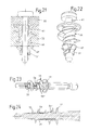
- FIGS. 11 to 14 show an example second embodiment of a screw plug 30 two different Setting tools 31,32, the one on the screw plug 30th out forward outstanding square shaft 33 with a Drill 34 have.
- Bohrende 34 is when setting of the screw plug 30 a hole predrilled, so that the fferdübel 30 no pointed expiring bore end needed and can be made correspondingly much shorter.
- the boring 34 is shaped so that the setting tool 31 and 32 also suitable for screwing Phillips screws.
- a third function of the wall parts 40 is the penetration of a Fastener 41 realized as the representations Figs. 19 and 20 illustrate.
- a Fastener 41 realized as the representations Figs. 19 and 20 illustrate.
- anchor latches 47 to the outside into the lightweight construction material and thus contribute to the additional Anchoring the screw anchor 35 at.
- the anchor latches 47 have a part of the inwardly projecting one Longitudinal ribs 24 and 25, so that the thread of the fastener 41 on this rib part the anchor latch 47th pushes outward.
- Screw anchor differs from the second Embodiment by the arrangement of several anchoring latches 49th at the same distance from the dowel end.
- a Fastener 41 in the screw dowel 48 they are first pressed something outward.
- Fig. 23 and Fig. 24 show a fourth embodiment of a Screw anchor 53.
- This has for engaging in a thicker Layer of lightweight material a greater length and points after a first, outgoing from the flange 11 thread or in a central region of the dowel longitudinal extension one circumferential set separation area 54, so that the front Part 55 of the screw plug is breakable, if a shorter Screw dowel 55 'corresponding to the rear part of such Long dowel 53 is needed.
- the target separation region slits separated by predetermined breaking points, so that after the breakage at them remains sharp-edged fragments of fracture, the later setting of the screw anchor 55 'the task of Drill teeth (37) according to the second embodiment assume the Fig.15 to 18.
- third and fourth embodiments are also a bit tool e.g. according to the illustrations of FIG. 1 to 3, but their use presupposes drilling in advance in a previous operation.
- To set the Screw anchor 30,48,53 in one operation is however a special, to use a drilling 34 having setting tool as shown in Figures 11 to 14 in engagement with a fferdübel 30 and in Fig.23 and 24 in engagement with a Screw plug 53 is shown.
- FIG. 12 to 14 differs from the already on hand 11 setting tool 31 by an additional Coil spring 56 through which the screw 30 already at the beginning of setting on the setting tool 32, a front position as shown in Fig.13 occupies and through which he drilled into the lightweight construction material one of the Spring force receives corresponding feed force.
- a feed force on the screw plug 30 be exercised and the setting of the screw plug 30 continued when the drilling end 34 of the setting tool 32 immediately after passing through a lightweight construction panel, e.g. at a concrete wall finds resistance.
- the screwing takes place until the flange 11 protrudes on the outside surfacechtbaustoff existing plate 52 buried and supported there.
- this is a drill with adjustable Torque is used as it is e.g. on commercial Cordless screwdriving is possible.
- the setting tools 13, 31 and 32 have a hexagonal coupling shaft 57,58 with standardized dimensions.
- the Setting tool according to Fig.11 closes to the coupling shaft 57 of the square guide shaft 33 at.
- setting tool 32 after 12 to 14 ends of the hexagonal coupling shaft 58 at one annular collar 59 and sits in a cylindrical Shank portion 60 of sufficient length continues to the pushed onto this coil spring 56 a guide to give.
Applications Claiming Priority (2)
| Application Number | Priority Date | Filing Date | Title |
|---|---|---|---|
| CH18162001 | 2001-10-01 | ||
| CH18162001 | 2001-10-01 |
Publications (3)
| Publication Number | Publication Date |
|---|---|
| EP1298331A2 true EP1298331A2 (fr) | 2003-04-02 |
| EP1298331A3 EP1298331A3 (fr) | 2003-08-13 |
| EP1298331B1 EP1298331B1 (fr) | 2006-06-07 |
Family
ID=4566373
Family Applications (1)
| Application Number | Title | Priority Date | Filing Date |
|---|---|---|---|
| EP02405755A Expired - Lifetime EP1298331B1 (fr) | 2001-10-01 | 2002-09-02 | Vis-cheville |
Country Status (3)
| Country | Link |
|---|---|
| EP (1) | EP1298331B1 (fr) |
| AT (1) | ATE329163T1 (fr) |
| DE (1) | DE50207083D1 (fr) |
Cited By (20)
| Publication number | Priority date | Publication date | Assignee | Title |
|---|---|---|---|---|
| EP1493929A1 (fr) * | 2003-07-03 | 2005-01-05 | Turner Intellectual Property Limited | Vis-cheville |
| EP1522744A1 (fr) * | 2003-10-10 | 2005-04-13 | Illinois Tool Works Inc. | Boulon d'ancrage autoperceur |
| FR2895295A1 (fr) * | 2005-12-23 | 2007-06-29 | Black & Decker Inc | Embout cruciforme de tournevis et tournevis comportant un tel embout |
| WO2007086988A3 (fr) * | 2005-11-30 | 2007-10-04 | Illinois Tool Works | Ancrage |
| US7661917B2 (en) | 2003-10-10 | 2010-02-16 | Illinois Tool Works, Inc. | Three piece garage hook |
| US7762751B2 (en) | 2004-02-05 | 2010-07-27 | Illinois Tool Works Inc. | Anchor |
| US8114226B2 (en) | 2008-03-14 | 2012-02-14 | Illinois Tool Works Inc. | Wall mountable holder |
| EP2039845A3 (fr) * | 2007-09-20 | 2012-04-04 | HILTI Aktiengesellschaft | Elément de fixation pour la fixation de plaques de matériau isolant sur un sous-sol |
| US8192123B2 (en) | 2003-10-10 | 2012-06-05 | Illinois Tool Works Inc. | Drywall fastener |
| US8272610B2 (en) | 2008-03-14 | 2012-09-25 | Illinois Tool Works Inc. | Wall mountable holder |
| US8317148B2 (en) | 2009-02-27 | 2012-11-27 | Illinois Tool Works Inc. | Wall mountable holder system |
| US8333356B2 (en) | 2009-11-02 | 2012-12-18 | Illinois Tool Works Inc. | Wall mountable holder system |
| US8448910B2 (en) | 2009-02-27 | 2013-05-28 | Illinois Tool Works Inc. | Wall mountable holder system |
| US8757570B2 (en) | 2009-02-27 | 2014-06-24 | Illinois Tool Works Inc. | Wall mountable holder system |
| EP3214321A1 (fr) * | 2016-03-01 | 2017-09-06 | Adolf Würth GmbH & Co. KG | Cheville pour panneau de construction léger, système comprenant un panneau de construction léger et une cheville et procédé d'insertion d'une cheville dans un panneau de construction léger |
| EP3249245A1 (fr) * | 2016-05-26 | 2017-11-29 | UK Building Products Ltd. | Dispositif d'ancrage autoperçant de cloison sèche et procédé de fixation d'un dispositif d'ancrage dans une cloison sèche |
| EP3399198A1 (fr) | 2017-05-05 | 2018-11-07 | fischerwerke GmbH & Co. KG | Cheville filetée |
| WO2019154485A1 (fr) | 2018-02-07 | 2019-08-15 | Mungo Befestigungstechnik Ag | Cheville murale auto-foreuse |
| USD860770S1 (en) | 2017-09-15 | 2019-09-24 | Fischerwerke Gmbh & Co. Kg | Anchor |
| CN113970487A (zh) * | 2021-10-25 | 2022-01-25 | 南京新核复合材料有限公司 | 玻璃钢管道水压试验内涨密封装置 |
Families Citing this family (4)
| Publication number | Priority date | Publication date | Assignee | Title |
|---|---|---|---|---|
| US7160074B2 (en) | 2004-09-13 | 2007-01-09 | Illinois Tool Works Inc. | Garage hook |
| US8057147B2 (en) | 2008-07-03 | 2011-11-15 | Illinois Tool Works Inc | Self-drilling anchor |
| US7883307B2 (en) | 2009-02-27 | 2011-02-08 | Illinois Tool Works Inc. | Self-drilling fastener |
| DE102011100247A1 (de) | 2011-04-26 | 2012-10-31 | Oswald Gleixner-Hauler | Verbindungssystem |
Citations (3)
| Publication number | Priority date | Publication date | Assignee | Title |
|---|---|---|---|---|
| FR2653503A1 (fr) | 1989-10-25 | 1991-04-26 | Legrand Sa | |
| DE4039831C1 (en) | 1990-12-13 | 1992-06-04 | Upat Gmbh & Co, 7830 Emmendingen, De | Object fastener to lightweight wall - has tool stem on setting tool as flat rod, whose drill tip is movable through insert inner cavity |
| DE4106467A1 (de) | 1991-02-28 | 1992-09-03 | Allfa Duebel Gmbh | Bausatz zum eindrehen von duebeln in poroeses material |
Family Cites Families (6)
| Publication number | Priority date | Publication date | Assignee | Title |
|---|---|---|---|---|
| FR1458166A (fr) * | 1965-05-07 | 1966-03-04 | Cheville en matière plastique pour le montage de vis, pitons et organes de fixation analogues | |
| US5690454A (en) * | 1992-11-23 | 1997-11-25 | Dry Dock Industries, Inc. | Anchoring retainer for threaded fasteners |
| CH687746A5 (de) * | 1993-11-25 | 1997-02-14 | Mungo Befestigungstech Ag | Werkzeug zum Einbringen eines mit Aussengewinde versehenen Befestigungselementes in Baumaterial. |
| US5558479A (en) * | 1995-05-19 | 1996-09-24 | Illinois Tool Works Inc. | Wall anchor accommodating fasteners of varying thread diameters |
| GB9929005D0 (en) * | 1999-12-09 | 2000-02-02 | Taylor Ronald | Anchorage |
| DE10038016A1 (de) * | 2000-08-04 | 2002-02-14 | Wuerth Adolf Gmbh & Co Kg | Dübel für Leichtbaustoffe |
-
2002
- 2002-09-02 DE DE50207083T patent/DE50207083D1/de not_active Expired - Lifetime
- 2002-09-02 EP EP02405755A patent/EP1298331B1/fr not_active Expired - Lifetime
- 2002-09-02 AT AT02405755T patent/ATE329163T1/de not_active IP Right Cessation
Patent Citations (3)
| Publication number | Priority date | Publication date | Assignee | Title |
|---|---|---|---|---|
| FR2653503A1 (fr) | 1989-10-25 | 1991-04-26 | Legrand Sa | |
| DE4039831C1 (en) | 1990-12-13 | 1992-06-04 | Upat Gmbh & Co, 7830 Emmendingen, De | Object fastener to lightweight wall - has tool stem on setting tool as flat rod, whose drill tip is movable through insert inner cavity |
| DE4106467A1 (de) | 1991-02-28 | 1992-09-03 | Allfa Duebel Gmbh | Bausatz zum eindrehen von duebeln in poroeses material |
Cited By (30)
| Publication number | Priority date | Publication date | Assignee | Title |
|---|---|---|---|---|
| US7237994B2 (en) | 2003-07-03 | 2007-07-03 | Turner Intellectual Property Limited | Wall plug |
| EP1493929A1 (fr) * | 2003-07-03 | 2005-01-05 | Turner Intellectual Property Limited | Vis-cheville |
| US7266874B2 (en) | 2003-10-10 | 2007-09-11 | Illinois Tool Works Inc. | Method of installing a self-drilling anchor |
| AU2004218639B2 (en) * | 2003-10-10 | 2007-03-08 | Illinois Tool Works Inc. | Self-drilling anchor |
| JP2005121224A (ja) * | 2003-10-10 | 2005-05-12 | Illinois Tool Works Inc <Itw> | セルフドリルアンカー |
| EP1522744A1 (fr) * | 2003-10-10 | 2005-04-13 | Illinois Tool Works Inc. | Boulon d'ancrage autoperceur |
| US7661917B2 (en) | 2003-10-10 | 2010-02-16 | Illinois Tool Works, Inc. | Three piece garage hook |
| US7934895B2 (en) | 2003-10-10 | 2011-05-03 | Illinois Tool Works Inc. | Self-drilling anchor |
| CN1605761B (zh) * | 2003-10-10 | 2011-06-15 | 伊利诺斯器械工程公司 | 自钻孔固定器 |
| US8192123B2 (en) | 2003-10-10 | 2012-06-05 | Illinois Tool Works Inc. | Drywall fastener |
| US7762751B2 (en) | 2004-02-05 | 2010-07-27 | Illinois Tool Works Inc. | Anchor |
| WO2007086988A3 (fr) * | 2005-11-30 | 2007-10-04 | Illinois Tool Works | Ancrage |
| CN101331329B (zh) * | 2005-11-30 | 2011-01-26 | 伊利诺斯工具制品有限公司 | 锚 |
| FR2895295A1 (fr) * | 2005-12-23 | 2007-06-29 | Black & Decker Inc | Embout cruciforme de tournevis et tournevis comportant un tel embout |
| EP2039845A3 (fr) * | 2007-09-20 | 2012-04-04 | HILTI Aktiengesellschaft | Elément de fixation pour la fixation de plaques de matériau isolant sur un sous-sol |
| US8114226B2 (en) | 2008-03-14 | 2012-02-14 | Illinois Tool Works Inc. | Wall mountable holder |
| US8272610B2 (en) | 2008-03-14 | 2012-09-25 | Illinois Tool Works Inc. | Wall mountable holder |
| US8317148B2 (en) | 2009-02-27 | 2012-11-27 | Illinois Tool Works Inc. | Wall mountable holder system |
| US8448910B2 (en) | 2009-02-27 | 2013-05-28 | Illinois Tool Works Inc. | Wall mountable holder system |
| US8757570B2 (en) | 2009-02-27 | 2014-06-24 | Illinois Tool Works Inc. | Wall mountable holder system |
| US8333356B2 (en) | 2009-11-02 | 2012-12-18 | Illinois Tool Works Inc. | Wall mountable holder system |
| EP3214321A1 (fr) * | 2016-03-01 | 2017-09-06 | Adolf Würth GmbH & Co. KG | Cheville pour panneau de construction léger, système comprenant un panneau de construction léger et une cheville et procédé d'insertion d'une cheville dans un panneau de construction léger |
| DE102016203308A1 (de) * | 2016-03-01 | 2017-09-07 | Adolf Würth GmbH & Co. KG | Dübel für Leichtbauplatten, Anordnung mit einer Leichtbauplatte und einem Dübel sowie Verfahren zum Einsetzen eines Dübels in eine Leichtbauplatte |
| EP3249245A1 (fr) * | 2016-05-26 | 2017-11-29 | UK Building Products Ltd. | Dispositif d'ancrage autoperçant de cloison sèche et procédé de fixation d'un dispositif d'ancrage dans une cloison sèche |
| EP3399198A1 (fr) | 2017-05-05 | 2018-11-07 | fischerwerke GmbH & Co. KG | Cheville filetée |
| USD860770S1 (en) | 2017-09-15 | 2019-09-24 | Fischerwerke Gmbh & Co. Kg | Anchor |
| WO2019154485A1 (fr) | 2018-02-07 | 2019-08-15 | Mungo Befestigungstechnik Ag | Cheville murale auto-foreuse |
| JP2021513033A (ja) * | 2018-02-07 | 2021-05-20 | ムンゴ ベフェスティガングステクニク アーゲーMungo Befestigungstechnik Ag | 自穿孔式壁プラグ |
| CN113970487A (zh) * | 2021-10-25 | 2022-01-25 | 南京新核复合材料有限公司 | 玻璃钢管道水压试验内涨密封装置 |
| CN113970487B (zh) * | 2021-10-25 | 2024-01-19 | 南京新核复合材料有限公司 | 玻璃钢管道水压试验内涨密封装置 |
Also Published As
| Publication number | Publication date |
|---|---|
| ATE329163T1 (de) | 2006-06-15 |
| EP1298331A3 (fr) | 2003-08-13 |
| DE50207083D1 (de) | 2006-07-20 |
| EP1298331B1 (fr) | 2006-06-07 |
Similar Documents
| Publication | Publication Date | Title |
|---|---|---|
| EP1298331A2 (fr) | Vis-cheville | |
| DE60210025T2 (de) | Wanddübel mit verbesserter Bohrspitze | |
| DE2521555C2 (de) | Schraube | |
| DE3936703C2 (fr) | ||
| DE2805071A1 (de) | Schraube | |
| EP1984632B1 (fr) | Cheville expansible | |
| DE2433294A1 (de) | Verankerungsvorrichtung fuer holz- und maschinenschrauben | |
| EP1305529B1 (fr) | Cheville pour materiaux legers, et utilisation d'un embout de tournevis pour visser une telle cheville | |
| DE4414765A1 (de) | Schraubbefestigung | |
| EP0575295B1 (fr) | Manchon à vis | |
| EP0463278A1 (fr) | Manchon à vis | |
| EP0874165A1 (fr) | Dispositif de fixation murale | |
| DE10134734A1 (de) | Spreizdübel | |
| EP2039845B1 (fr) | Elément de fixation pour la fixation de plaques de matériau isolant sur un sous-sol | |
| DE19956906A1 (de) | Isolierdübel | |
| DE8401123U1 (de) | Formschlußdübel für Beton | |
| DE19931794A1 (de) | Isolierdübel | |
| EP0045974B1 (fr) | Fixation d'une cheville au moyen d'un clou | |
| DE4010999A1 (de) | Befestigungselement | |
| DE4106467C2 (de) | Bausatz zum Eindrehen von Dübeln in poröses Material | |
| DE102007005280A1 (de) | Spreizdübel | |
| DE3820759A1 (de) | Spreizduebel zum einschlagen in ein bohrloch mit hinterschneidung | |
| DE102021209067A1 (de) | Befestigungssystem und Verfahren zum vertieften Halten von Dämmstoffelementen | |
| DE3615091A1 (de) | Befestigungsduebel | |
| EP3882475A1 (fr) | Cheville en placoplâtre et combinaison de la cheville en placoplâtre avec un outil de perçage et de tournage |
Legal Events
| Date | Code | Title | Description |
|---|---|---|---|
| PUAI | Public reference made under article 153(3) epc to a published international application that has entered the european phase |
Free format text: ORIGINAL CODE: 0009012 |
|
| AK | Designated contracting states |
Kind code of ref document: A2 Designated state(s): AT BE BG CH CY CZ DE DK EE ES FI FR GB GR IE IT LI LU MC NL PT SE SK TR |
|
| AX | Request for extension of the european patent |
Extension state: AL LT LV MK RO SI |
|
| PUAL | Search report despatched |
Free format text: ORIGINAL CODE: 0009013 |
|
| AK | Designated contracting states |
Designated state(s): AT BE BG CH CY CZ DE DK EE ES FI FR GB GR IE IT LI LU MC NL PT SE SK TR |
|
| AX | Request for extension of the european patent |
Extension state: AL LT LV MK RO SI |
|
| RIC1 | Information provided on ipc code assigned before grant |
Ipc: 7F 16B 13/12 B Ipc: 7F 16B 37/12 B Ipc: 7F 16B 23/00 B Ipc: 7F 16B 37/00 B Ipc: 7B 25B 15/00 B Ipc: 7F 16B 13/00 A Ipc: 7F 16B 13/02 B |
|
| 17P | Request for examination filed |
Effective date: 20040213 |
|
| AKX | Designation fees paid |
Designated state(s): AT BE BG CH CY CZ DE DK EE ES FI FR GB GR IE IT LI LU MC NL PT SE SK TR |
|
| 17Q | First examination report despatched |
Effective date: 20050506 |
|
| GRAP | Despatch of communication of intention to grant a patent |
Free format text: ORIGINAL CODE: EPIDOSNIGR1 |
|
| GRAS | Grant fee paid |
Free format text: ORIGINAL CODE: EPIDOSNIGR3 |
|
| GRAA | (expected) grant |
Free format text: ORIGINAL CODE: 0009210 |
|
| AK | Designated contracting states |
Kind code of ref document: B1 Designated state(s): AT BE BG CH CY CZ DE DK EE ES FI FR GB GR IE IT LI LU MC NL PT SE SK TR |
|
| PG25 | Lapsed in a contracting state [announced via postgrant information from national office to epo] |
Ref country code: IT Free format text: LAPSE BECAUSE OF FAILURE TO SUBMIT A TRANSLATION OF THE DESCRIPTION OR TO PAY THE FEE WITHIN THE PRESCRIBED TIME-LIMIT;WARNING: LAPSES OF ITALIAN PATENTS WITH EFFECTIVE DATE BEFORE 2007 MAY HAVE OCCURRED AT ANY TIME BEFORE 2007. THE CORRECT EFFECTIVE DATE MAY BE DIFFERENT FROM THE ONE RECORDED. Effective date: 20060607 Ref country code: NL Free format text: LAPSE BECAUSE OF FAILURE TO SUBMIT A TRANSLATION OF THE DESCRIPTION OR TO PAY THE FEE WITHIN THE PRESCRIBED TIME-LIMIT Effective date: 20060607 Ref country code: IE Free format text: LAPSE BECAUSE OF FAILURE TO SUBMIT A TRANSLATION OF THE DESCRIPTION OR TO PAY THE FEE WITHIN THE PRESCRIBED TIME-LIMIT Effective date: 20060607 Ref country code: SK Free format text: LAPSE BECAUSE OF FAILURE TO SUBMIT A TRANSLATION OF THE DESCRIPTION OR TO PAY THE FEE WITHIN THE PRESCRIBED TIME-LIMIT Effective date: 20060607 Ref country code: CZ Free format text: LAPSE BECAUSE OF FAILURE TO SUBMIT A TRANSLATION OF THE DESCRIPTION OR TO PAY THE FEE WITHIN THE PRESCRIBED TIME-LIMIT Effective date: 20060607 Ref country code: FI Free format text: LAPSE BECAUSE OF FAILURE TO SUBMIT A TRANSLATION OF THE DESCRIPTION OR TO PAY THE FEE WITHIN THE PRESCRIBED TIME-LIMIT Effective date: 20060607 |
|
| REG | Reference to a national code |
Ref country code: GB Ref legal event code: FG4D Free format text: NOT ENGLISH |
|
| REG | Reference to a national code |
Ref country code: CH Ref legal event code: EP |
|
| REG | Reference to a national code |
Ref country code: CH Ref legal event code: NV Representative=s name: DIPL.-ING. HORST QUEHL PATENTANWALT |
|
| REG | Reference to a national code |
Ref country code: IE Ref legal event code: FG4D Free format text: LANGUAGE OF EP DOCUMENT: GERMAN |
|
| GBT | Gb: translation of ep patent filed (gb section 77(6)(a)/1977) |
Effective date: 20060626 |
|
| REF | Corresponds to: |
Ref document number: 50207083 Country of ref document: DE Date of ref document: 20060720 Kind code of ref document: P |
|
| PG25 | Lapsed in a contracting state [announced via postgrant information from national office to epo] |
Ref country code: SE Free format text: LAPSE BECAUSE OF FAILURE TO SUBMIT A TRANSLATION OF THE DESCRIPTION OR TO PAY THE FEE WITHIN THE PRESCRIBED TIME-LIMIT Effective date: 20060907 Ref country code: DK Free format text: LAPSE BECAUSE OF FAILURE TO SUBMIT A TRANSLATION OF THE DESCRIPTION OR TO PAY THE FEE WITHIN THE PRESCRIBED TIME-LIMIT Effective date: 20060907 |
|
| PG25 | Lapsed in a contracting state [announced via postgrant information from national office to epo] |
Ref country code: ES Free format text: LAPSE BECAUSE OF FAILURE TO SUBMIT A TRANSLATION OF THE DESCRIPTION OR TO PAY THE FEE WITHIN THE PRESCRIBED TIME-LIMIT Effective date: 20060918 |
|
| PG25 | Lapsed in a contracting state [announced via postgrant information from national office to epo] |
Ref country code: MC Free format text: LAPSE BECAUSE OF NON-PAYMENT OF DUE FEES Effective date: 20060930 Ref country code: BE Free format text: LAPSE BECAUSE OF NON-PAYMENT OF DUE FEES Effective date: 20060930 |
|
| ET | Fr: translation filed | ||
| PG25 | Lapsed in a contracting state [announced via postgrant information from national office to epo] |
Ref country code: PT Free format text: LAPSE BECAUSE OF FAILURE TO SUBMIT A TRANSLATION OF THE DESCRIPTION OR TO PAY THE FEE WITHIN THE PRESCRIBED TIME-LIMIT Effective date: 20061107 |
|
| NLV1 | Nl: lapsed or annulled due to failure to fulfill the requirements of art. 29p and 29m of the patents act | ||
| REG | Reference to a national code |
Ref country code: IE Ref legal event code: FD4D |
|
| PLBE | No opposition filed within time limit |
Free format text: ORIGINAL CODE: 0009261 |
|
| STAA | Information on the status of an ep patent application or granted ep patent |
Free format text: STATUS: NO OPPOSITION FILED WITHIN TIME LIMIT |
|
| 26N | No opposition filed |
Effective date: 20070308 |
|
| PG25 | Lapsed in a contracting state [announced via postgrant information from national office to epo] |
Ref country code: AT Free format text: LAPSE BECAUSE OF NON-PAYMENT OF DUE FEES Effective date: 20060902 |
|
| BERE | Be: lapsed |
Owner name: MUNGO BEFESTIGUNGSTECHNIK A.G. Effective date: 20060930 |
|
| PG25 | Lapsed in a contracting state [announced via postgrant information from national office to epo] |
Ref country code: GR Free format text: LAPSE BECAUSE OF FAILURE TO SUBMIT A TRANSLATION OF THE DESCRIPTION OR TO PAY THE FEE WITHIN THE PRESCRIBED TIME-LIMIT Effective date: 20060908 |
|
| PG25 | Lapsed in a contracting state [announced via postgrant information from national office to epo] |
Ref country code: EE Free format text: LAPSE BECAUSE OF FAILURE TO SUBMIT A TRANSLATION OF THE DESCRIPTION OR TO PAY THE FEE WITHIN THE PRESCRIBED TIME-LIMIT Effective date: 20060607 Ref country code: BG Free format text: LAPSE BECAUSE OF FAILURE TO SUBMIT A TRANSLATION OF THE DESCRIPTION OR TO PAY THE FEE WITHIN THE PRESCRIBED TIME-LIMIT Effective date: 20060907 |
|
| PG25 | Lapsed in a contracting state [announced via postgrant information from national office to epo] |
Ref country code: LU Free format text: LAPSE BECAUSE OF NON-PAYMENT OF DUE FEES Effective date: 20060902 Ref country code: TR Free format text: LAPSE BECAUSE OF FAILURE TO SUBMIT A TRANSLATION OF THE DESCRIPTION OR TO PAY THE FEE WITHIN THE PRESCRIBED TIME-LIMIT Effective date: 20060607 |
|
| PG25 | Lapsed in a contracting state [announced via postgrant information from national office to epo] |
Ref country code: CY Free format text: LAPSE BECAUSE OF FAILURE TO SUBMIT A TRANSLATION OF THE DESCRIPTION OR TO PAY THE FEE WITHIN THE PRESCRIBED TIME-LIMIT Effective date: 20060607 |
|
| REG | Reference to a national code |
Ref country code: CH Ref legal event code: NV Representative=s name: ZIMMERLI, WAGNER & PARTNER AG |
|
| PGFP | Annual fee paid to national office [announced via postgrant information from national office to epo] |
Ref country code: DE Payment date: 20130919 Year of fee payment: 12 Ref country code: CH Payment date: 20130924 Year of fee payment: 12 |
|
| REG | Reference to a national code |
Ref country code: CH Ref legal event code: NV Representative=s name: WAGNER PATENT AG, CH |
|
| REG | Reference to a national code |
Ref country code: DE Ref legal event code: R119 Ref document number: 50207083 Country of ref document: DE |
|
| REG | Reference to a national code |
Ref country code: CH Ref legal event code: PL |
|
| PG25 | Lapsed in a contracting state [announced via postgrant information from national office to epo] |
Ref country code: DE Free format text: LAPSE BECAUSE OF NON-PAYMENT OF DUE FEES Effective date: 20150401 Ref country code: CH Free format text: LAPSE BECAUSE OF NON-PAYMENT OF DUE FEES Effective date: 20140930 Ref country code: LI Free format text: LAPSE BECAUSE OF NON-PAYMENT OF DUE FEES Effective date: 20140930 |
|
| REG | Reference to a national code |
Ref country code: FR Ref legal event code: PLFP Year of fee payment: 15 |
|
| REG | Reference to a national code |
Ref country code: FR Ref legal event code: PLFP Year of fee payment: 16 |
|
| REG | Reference to a national code |
Ref country code: FR Ref legal event code: PLFP Year of fee payment: 17 |
|
| PGFP | Annual fee paid to national office [announced via postgrant information from national office to epo] |
Ref country code: FR Payment date: 20190925 Year of fee payment: 18 |
|
| PGFP | Annual fee paid to national office [announced via postgrant information from national office to epo] |
Ref country code: GB Payment date: 20190920 Year of fee payment: 18 |
|
| GBPC | Gb: european patent ceased through non-payment of renewal fee |
Effective date: 20200902 |
|
| PG25 | Lapsed in a contracting state [announced via postgrant information from national office to epo] |
Ref country code: FR Free format text: LAPSE BECAUSE OF NON-PAYMENT OF DUE FEES Effective date: 20200930 |
|
| PG25 | Lapsed in a contracting state [announced via postgrant information from national office to epo] |
Ref country code: GB Free format text: LAPSE BECAUSE OF NON-PAYMENT OF DUE FEES Effective date: 20200902 |