EP1298331A2 - Screw-plug - Google Patents
Screw-plug Download PDFInfo
- Publication number
- EP1298331A2 EP1298331A2 EP02405755A EP02405755A EP1298331A2 EP 1298331 A2 EP1298331 A2 EP 1298331A2 EP 02405755 A EP02405755 A EP 02405755A EP 02405755 A EP02405755 A EP 02405755A EP 1298331 A2 EP1298331 A2 EP 1298331A2
- Authority
- EP
- European Patent Office
- Prior art keywords
- screw
- plug
- anchor
- engagement
- flange
- Prior art date
- Legal status (The legal status is an assumption and is not a legal conclusion. Google has not performed a legal analysis and makes no representation as to the accuracy of the status listed.)
- Granted
Links
- 238000005553 drilling Methods 0.000 claims description 12
- 230000008878 coupling Effects 0.000 claims description 10
- 238000010168 coupling process Methods 0.000 claims description 10
- 238000005859 coupling reaction Methods 0.000 claims description 10
- 239000003562 lightweight material Substances 0.000 claims description 3
- 238000000926 separation method Methods 0.000 claims description 3
- 230000002093 peripheral effect Effects 0.000 claims 1
- 239000004035 construction material Substances 0.000 description 6
- 238000004873 anchoring Methods 0.000 description 5
- 239000004566 building material Substances 0.000 description 4
- 238000010276 construction Methods 0.000 description 2
- 230000035515 penetration Effects 0.000 description 2
- 238000010521 absorption reaction Methods 0.000 description 1
- 230000001419 dependent effect Effects 0.000 description 1
- 239000000428 dust Substances 0.000 description 1
- 239000012634 fragment Substances 0.000 description 1
- 238000003780 insertion Methods 0.000 description 1
- 230000037431 insertion Effects 0.000 description 1
- 230000036346 tooth eruption Effects 0.000 description 1
Images


Classifications
-
- B—PERFORMING OPERATIONS; TRANSPORTING
- B25—HAND TOOLS; PORTABLE POWER-DRIVEN TOOLS; MANIPULATORS
- B25B—TOOLS OR BENCH DEVICES NOT OTHERWISE PROVIDED FOR, FOR FASTENING, CONNECTING, DISENGAGING OR HOLDING
- B25B15/00—Screwdrivers
- B25B15/001—Screwdrivers characterised by material or shape of the tool bit
- B25B15/004—Screwdrivers characterised by material or shape of the tool bit characterised by cross-section
- B25B15/005—Screwdrivers characterised by material or shape of the tool bit characterised by cross-section with cross- or star-shaped cross-section
-
- F—MECHANICAL ENGINEERING; LIGHTING; HEATING; WEAPONS; BLASTING
- F16—ENGINEERING ELEMENTS AND UNITS; GENERAL MEASURES FOR PRODUCING AND MAINTAINING EFFECTIVE FUNCTIONING OF MACHINES OR INSTALLATIONS; THERMAL INSULATION IN GENERAL
- F16B—DEVICES FOR FASTENING OR SECURING CONSTRUCTIONAL ELEMENTS OR MACHINE PARTS TOGETHER, e.g. NAILS, BOLTS, CIRCLIPS, CLAMPS, CLIPS OR WEDGES; JOINTS OR JOINTING
- F16B13/00—Dowels or other devices fastened in walls or the like by inserting them in holes made therein for that purpose
- F16B13/002—Dowels or other devices fastened in walls or the like by inserting them in holes made therein for that purpose self-cutting
-
- F—MECHANICAL ENGINEERING; LIGHTING; HEATING; WEAPONS; BLASTING
- F16—ENGINEERING ELEMENTS AND UNITS; GENERAL MEASURES FOR PRODUCING AND MAINTAINING EFFECTIVE FUNCTIONING OF MACHINES OR INSTALLATIONS; THERMAL INSULATION IN GENERAL
- F16B—DEVICES FOR FASTENING OR SECURING CONSTRUCTIONAL ELEMENTS OR MACHINE PARTS TOGETHER, e.g. NAILS, BOLTS, CIRCLIPS, CLAMPS, CLIPS OR WEDGES; JOINTS OR JOINTING
- F16B13/00—Dowels or other devices fastened in walls or the like by inserting them in holes made therein for that purpose
- F16B13/02—Dowels or other devices fastened in walls or the like by inserting them in holes made therein for that purpose in one piece with protrusions or ridges on the shaft
-
- F—MECHANICAL ENGINEERING; LIGHTING; HEATING; WEAPONS; BLASTING
- F16—ENGINEERING ELEMENTS AND UNITS; GENERAL MEASURES FOR PRODUCING AND MAINTAINING EFFECTIVE FUNCTIONING OF MACHINES OR INSTALLATIONS; THERMAL INSULATION IN GENERAL
- F16B—DEVICES FOR FASTENING OR SECURING CONSTRUCTIONAL ELEMENTS OR MACHINE PARTS TOGETHER, e.g. NAILS, BOLTS, CIRCLIPS, CLAMPS, CLIPS OR WEDGES; JOINTS OR JOINTING
- F16B13/00—Dowels or other devices fastened in walls or the like by inserting them in holes made therein for that purpose
- F16B13/12—Separate metal or non-separate or non-metal dowel sleeves fastened by inserting the screw, nail or the like
- F16B13/128—Separate metal or non-separate or non-metal dowel sleeves fastened by inserting the screw, nail or the like with extending protrusions, e.g. discs, segments, ridges, fingers or tongues
-
- F—MECHANICAL ENGINEERING; LIGHTING; HEATING; WEAPONS; BLASTING
- F16—ENGINEERING ELEMENTS AND UNITS; GENERAL MEASURES FOR PRODUCING AND MAINTAINING EFFECTIVE FUNCTIONING OF MACHINES OR INSTALLATIONS; THERMAL INSULATION IN GENERAL
- F16B—DEVICES FOR FASTENING OR SECURING CONSTRUCTIONAL ELEMENTS OR MACHINE PARTS TOGETHER, e.g. NAILS, BOLTS, CIRCLIPS, CLAMPS, CLIPS OR WEDGES; JOINTS OR JOINTING
- F16B23/00—Specially shaped nuts or heads of bolts or screws for rotations by a tool
- F16B23/0007—Specially shaped nuts or heads of bolts or screws for rotations by a tool characterised by the shape of the recess or the protrusion engaging the tool
- F16B23/003—Specially shaped nuts or heads of bolts or screws for rotations by a tool characterised by the shape of the recess or the protrusion engaging the tool star-shaped or multi-lobular, e.g. Torx-type, twelve-point star
-
- F—MECHANICAL ENGINEERING; LIGHTING; HEATING; WEAPONS; BLASTING
- F16—ENGINEERING ELEMENTS AND UNITS; GENERAL MEASURES FOR PRODUCING AND MAINTAINING EFFECTIVE FUNCTIONING OF MACHINES OR INSTALLATIONS; THERMAL INSULATION IN GENERAL
- F16B—DEVICES FOR FASTENING OR SECURING CONSTRUCTIONAL ELEMENTS OR MACHINE PARTS TOGETHER, e.g. NAILS, BOLTS, CIRCLIPS, CLAMPS, CLIPS OR WEDGES; JOINTS OR JOINTING
- F16B23/00—Specially shaped nuts or heads of bolts or screws for rotations by a tool
- F16B23/0007—Specially shaped nuts or heads of bolts or screws for rotations by a tool characterised by the shape of the recess or the protrusion engaging the tool
- F16B23/0038—Specially shaped nuts or heads of bolts or screws for rotations by a tool characterised by the shape of the recess or the protrusion engaging the tool substantially prismatic with up to six edges, e.g. triangular, square, pentagonal, Allen-type cross-sections
-
- F—MECHANICAL ENGINEERING; LIGHTING; HEATING; WEAPONS; BLASTING
- F16—ENGINEERING ELEMENTS AND UNITS; GENERAL MEASURES FOR PRODUCING AND MAINTAINING EFFECTIVE FUNCTIONING OF MACHINES OR INSTALLATIONS; THERMAL INSULATION IN GENERAL
- F16B—DEVICES FOR FASTENING OR SECURING CONSTRUCTIONAL ELEMENTS OR MACHINE PARTS TOGETHER, e.g. NAILS, BOLTS, CIRCLIPS, CLAMPS, CLIPS OR WEDGES; JOINTS OR JOINTING
- F16B37/00—Nuts or like thread-engaging members
- F16B37/005—Nuts or like thread-engaging members into which threads are cut during screwing
-
- F—MECHANICAL ENGINEERING; LIGHTING; HEATING; WEAPONS; BLASTING
- F16—ENGINEERING ELEMENTS AND UNITS; GENERAL MEASURES FOR PRODUCING AND MAINTAINING EFFECTIVE FUNCTIONING OF MACHINES OR INSTALLATIONS; THERMAL INSULATION IN GENERAL
- F16B—DEVICES FOR FASTENING OR SECURING CONSTRUCTIONAL ELEMENTS OR MACHINE PARTS TOGETHER, e.g. NAILS, BOLTS, CIRCLIPS, CLAMPS, CLIPS OR WEDGES; JOINTS OR JOINTING
- F16B37/00—Nuts or like thread-engaging members
- F16B37/12—Nuts or like thread-engaging members with thread-engaging surfaces formed by inserted coil-springs, discs, or the like; Independent pieces of wound wire used as nuts; Threaded inserts for holes
- F16B37/122—Threaded inserts, e.g. "rampa bolts"
- F16B37/125—Threaded inserts, e.g. "rampa bolts" the external surface of the insert being threaded
- F16B37/127—Threaded inserts, e.g. "rampa bolts" the external surface of the insert being threaded and self-tapping
Definitions
- the invention relates to a screw plug according to the Preamble of claim 1.
- Screw dowels with setting tool are known from FR-A-2 653 503 and DE-A-41 06 467.
- Your setting tool has a long shaft with a drilling end, the pre-drilling a dowel receiving hole serves.
- this shaft is on a Schafterweittation a special intervention profiling provided for making a coupling in a matching profiled recess of the screw plug form fit intervenes.
- the screw can due to the drilling rotational movement of the setting tool with its front cutting teeth and its thread into a lightweight building material, e.g. a plasterboard.
- DE-A-40 39 831 is also a screw with Setting tool known in which the coupling between the two through a flat tool shank and a suitably shaped, extending through the entire screw plug engaging groove takes place, so that a coupling engagement over the entire dowel length given is.
- the drill bit of the setting tools according to FR-A-2 653 503 and DE-A-40 39 831 is also shaped so that the Setting tool after setting the screw anchor also for screwing a Phillips screw can be used.
- the known screw anchors have the disadvantage that they only set with the trained for them setting tool can be and that their setting tool in addition only to Screwing in Phillips screws can be used.
- the Screw dowel FR-A-2 653 503 and DE-41 06 467 have also the disadvantage that the thread of a fastener or a screw in the cylindrical inner wall of the screw anchor, so that this a relatively high torque is required by that the engagement connection between the screw plug and the Lightweight construction material can be destroyed.
- the screw anchors 1 shown in Figures 1 to 5 have a sleeve-shaped dowel body 2, the one to be cut enclosed in lightweight construction thread 3 is. Towards the front, the screw anchor 1 ends in a drill bit 4, so that he drilled self-drilling in lightweight construction material can be. For the absorption of Bohrmehl are in the sleeve-shaped dowel body 2, adjacent to the drill bit, laterally and forwards to the drill bit 4 through openings 5 to 7 intended. In a further opening 8 of the dowel body. 2 An anchor latch 9 is provided, which when screwing a Fastener 10 is pressed into the screw plug 1 to the outside and thus anchoring in the surrounding lightweight building material improved.
- the torque required for screwing in the screw anchor 1 is by the engagement of a setting tool 13 in the Transfer screw anchor 1. Due to the invention may additionally to a special, designed for the screw plug Setting tool with Oberschlitzeingriff, also one under the Designation "bit" market known screwing tool 14 -16 used be almost all users about the screwing already has screws.
- FIGS. 1 to 3 show exemplary embodiments such bit tools, all one identical having molded and dimensioned hex shank.
- a screw according to the invention also a novel Arrangement of along its inner wall 23 by longitudinal ribs 24,25 formed internal profiling. This arrangement prevents an engagement head 26 or 27 of a bit tool 15 or 16 with six engagement ribs 28 and 29 on the longitudinal ribs 24,25 abuts and thus a positive engagement of the bit tool 15 or 16 in the screw plug 1 becomes impossible.
- the illustrations in Figures 8 and 9 show this novel arrangement with four longitudinal ribs 24,25, with a larger and a smaller distance between two pairs of ribs in diametrical in pairs the same arrangement.
- the smaller distance between a pair of longitudinal ribs corresponds to an angle of 60 degrees and must be in the range of 60 to 80 degrees.
- the 8 and 9 also make it clear that the arrangement of Longitudinal ribs 24,25 allows the engagement of Bittechnikmaschineen, which have a two-, four- or six-edged engaging head.
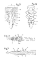
- FIGS. 11 to 14 show an example second embodiment of a screw plug 30 two different Setting tools 31,32, the one on the screw plug 30th out forward outstanding square shaft 33 with a Drill 34 have.
- Bohrende 34 is when setting of the screw plug 30 a hole predrilled, so that the fferdübel 30 no pointed expiring bore end needed and can be made correspondingly much shorter.
- the boring 34 is shaped so that the setting tool 31 and 32 also suitable for screwing Phillips screws.
- a third function of the wall parts 40 is the penetration of a Fastener 41 realized as the representations Figs. 19 and 20 illustrate.
- a Fastener 41 realized as the representations Figs. 19 and 20 illustrate.
- anchor latches 47 to the outside into the lightweight construction material and thus contribute to the additional Anchoring the screw anchor 35 at.
- the anchor latches 47 have a part of the inwardly projecting one Longitudinal ribs 24 and 25, so that the thread of the fastener 41 on this rib part the anchor latch 47th pushes outward.
- Screw anchor differs from the second Embodiment by the arrangement of several anchoring latches 49th at the same distance from the dowel end.
- a Fastener 41 in the screw dowel 48 they are first pressed something outward.
- Fig. 23 and Fig. 24 show a fourth embodiment of a Screw anchor 53.
- This has for engaging in a thicker Layer of lightweight material a greater length and points after a first, outgoing from the flange 11 thread or in a central region of the dowel longitudinal extension one circumferential set separation area 54, so that the front Part 55 of the screw plug is breakable, if a shorter Screw dowel 55 'corresponding to the rear part of such Long dowel 53 is needed.
- the target separation region slits separated by predetermined breaking points, so that after the breakage at them remains sharp-edged fragments of fracture, the later setting of the screw anchor 55 'the task of Drill teeth (37) according to the second embodiment assume the Fig.15 to 18.
- third and fourth embodiments are also a bit tool e.g. according to the illustrations of FIG. 1 to 3, but their use presupposes drilling in advance in a previous operation.
- To set the Screw anchor 30,48,53 in one operation is however a special, to use a drilling 34 having setting tool as shown in Figures 11 to 14 in engagement with a fferdübel 30 and in Fig.23 and 24 in engagement with a Screw plug 53 is shown.
- FIG. 12 to 14 differs from the already on hand 11 setting tool 31 by an additional Coil spring 56 through which the screw 30 already at the beginning of setting on the setting tool 32, a front position as shown in Fig.13 occupies and through which he drilled into the lightweight construction material one of the Spring force receives corresponding feed force.
- a feed force on the screw plug 30 be exercised and the setting of the screw plug 30 continued when the drilling end 34 of the setting tool 32 immediately after passing through a lightweight construction panel, e.g. at a concrete wall finds resistance.
- the screwing takes place until the flange 11 protrudes on the outside surfacechtbaustoff existing plate 52 buried and supported there.
- this is a drill with adjustable Torque is used as it is e.g. on commercial Cordless screwdriving is possible.
- the setting tools 13, 31 and 32 have a hexagonal coupling shaft 57,58 with standardized dimensions.
- the Setting tool according to Fig.11 closes to the coupling shaft 57 of the square guide shaft 33 at.
- setting tool 32 after 12 to 14 ends of the hexagonal coupling shaft 58 at one annular collar 59 and sits in a cylindrical Shank portion 60 of sufficient length continues to the pushed onto this coil spring 56 a guide to give.
Landscapes
- Engineering & Computer Science (AREA)
- General Engineering & Computer Science (AREA)
- Mechanical Engineering (AREA)
- Dowels (AREA)
- Joining Of Building Structures In Genera (AREA)
- Mutual Connection Of Rods And Tubes (AREA)
Abstract
Description
Die Erfindung betrifft einen Schraubdübel entsprechend dem
Oberbegriff des Anspruchs 1.The invention relates to a screw plug according to the
Preamble of
Schraubdübel mit Setzwerkzeug sind bekannt durch die FR-A-2 653 503 und die DE-A-41 06 467. Ihr Setzwerkzeug hat einen langen Schaft mit einem Bohrende, das dem Vorbohren eines Dübelaufnahmelochs dient. Im hinteren Bereich dieses Schaftes ist an einer Schafterweiterung eine besondere Eingriffsprofilierung vorgesehen, die zur Herstellung einer Kopplung in eine dazu passend profilierte Ausnehmung des Schraubdübel formschlüssig eingreift. Auf diese Weise kann sich der Schraubdübel aufgrund der dem Bohren dienenden-Drehbewegung des Setzwerkzeuges mit seinen vorderen Schneidzähnen und seinem Gewinde in einen Leichtbaustoff, z.B. eine Gipsplatte, einschneiden.Screw dowels with setting tool are known from FR-A-2 653 503 and DE-A-41 06 467. Your setting tool has a long shaft with a drilling end, the pre-drilling a dowel receiving hole serves. In the back of this shaft is on a Schafterweiterung a special intervention profiling provided for making a coupling in a matching profiled recess of the screw plug form fit intervenes. In this way, the screw can due to the drilling rotational movement of the setting tool with its front cutting teeth and its thread into a lightweight building material, e.g. a plasterboard.
Durch die DE-A-40 39 831 ist ausserdem ein Schraubdübel mit Setzwerkzeug bekannt, bei dem die Kopplung zwischen beiden durch einen flachen Werkzeugschaft und eine passend geformte, sich durch den gesamten Schraubdübel erstreckende Eingriffsnut erfolgt, so dass ein Kopplungseingriff über die gesamte Dübellänge gegeben ist.By DE-A-40 39 831 is also a screw with Setting tool known in which the coupling between the two through a flat tool shank and a suitably shaped, extending through the entire screw plug engaging groove takes place, so that a coupling engagement over the entire dowel length given is.
Die Bohrspitze der Setzwerkzeuge entsprechend der FR-A-2 653 503 und der DE-A-40 39 831 ist ausserdem so geformt, dass das Setzwerkzeug nach dem Setzen des Schraubdübels auch zum Einschrauben einer Kreuzschlitzschraube verwendet werden kann.The drill bit of the setting tools according to FR-A-2 653 503 and DE-A-40 39 831 is also shaped so that the Setting tool after setting the screw anchor also for screwing a Phillips screw can be used.
Die bekannten Schraubdübel haben den Nachteil, dass sie nur zusammen mit dem für sie ausgebildeten Setzwerkzeug gesetzt werden können und dass ihr Setzwerkzeug zusätzlich nur zum Einschrauben von Kreuzschlitzschrauben einsetzbar ist. Die Schraubdübel der FR-A-2 653 503 und der DE-41 06 467 haben auch den Nachteil, dass sich das Gewinde eines Befestigungselementes bzw. einer Schraube in die zylindrische Innenwand des Schraubdübels einschneiden muss, so dass hierzu ein verhältnismässig hohes Drehmoment erforderlich ist, durch dass die Eingriffsverbindung zwischen dem Schraubdübel und dem Leichtbaustoff zerstört werden kann.The known screw anchors have the disadvantage that they only set with the trained for them setting tool can be and that their setting tool in addition only to Screwing in Phillips screws can be used. The Screw dowel FR-A-2 653 503 and DE-41 06 467 have also the disadvantage that the thread of a fastener or a screw in the cylindrical inner wall of the screw anchor, so that this a relatively high torque is required by that the engagement connection between the screw plug and the Lightweight construction material can be destroyed.
Der Erfindung liegt die Aufgabe zugrunde, die genannten
Nachteile zu vermeiden und einen Schraubdübel zu finden, der
zum Setzen nicht ein speziell für ihn geformtes Setzwerkzeug
erfordert und somit mit verschiedenartigen Setzwerkzeugen
setzbar. Die Lösung dieser Aufgabe erfolgt aufgrund der kennzeichnenden
Merkmale des Patentanspruchs 1. Vorteilhafte Ausführungsbeispiele
der Erfindung sind Gegenstand der abhängigen
Patentansprüche und werden im Folgenden an Hand der Zeichnungen
beschrieben. Es zeigen:
Die in den Fig.1 bis Fig.5 dargestellten Schraubdübel 1 haben
einen hülsenförmigen Dübelkörper 2, der von einem zum Einschneiden
in Leichtbaustoff geeigneten Gewindegang 3 umschlossen
ist. Nach vorn endet der Schraubdübel 1 in einer Bohrspitze
4, so dass er selbstbohrend in Leichtbaustoff eingebohrt
werden kann. Für die Aufnahme von Bohrmehl sind in dem
hülsenförmigern Dübelkörper 2, angrenzend an die Bohrspitze,
seitlich und nach vorn zur Bohrspitze 4 hin Öffnungen 5 bis 7
vorgesehen. In einer weiteren Öffnung 8 des Dübelkörpers 2
ist eine Ankerklinke 9 vorgesehen, die beim Einschrauben eines
Befestigungselementes 10 in den Schraubdübel 1 nach aussen gedrückt
wird und somit die Verankerung im umgebenden Leichtbaustoff
verbessert. Eine nähere Beschreibung und deutlichere
Darstellung der Ankerklinke 9 folgt an Hand einer weiteren
Ausführungsform eines Schraubdübels entsprechend den Fig. 14
bis 18. Für die Abstützung an der Bauwerksoberfläche hat der
Schraubdübel 1 an seinem hinteren Ende einen Flansch 11. Rippen
12 an seiner Unterseite unterstützen die torsionsfeste
Verankerung des Schraubdübels 1 im Leichtbaustoff.The
Das zum Einschrauben des Schraubdübels 1 erforderliche Drehmoment
wird durch den Eingriff eines Setzwerkzeuges 13 in den
Schraubdübel 1 übertragen. Aufgrund der Erfindung kann zusätzlich
zu einem speziellen, für den Schraubdübel gestalteten
Setzwerkzeuges mit Kreuzschlitzeingriff, auch ein unter der
Bezeichnung "Bit" marktbekanntes Schraubwerkzeug 14 -16 verwendet
werden, über das nahezu jeder Anwender zum Eindrehen
von Schrauben bereits verfügt. Die Fig.1 bis Fig.3 zeigen Ausführungsbeispiele
solcher Bitwerkzeuge, die alle einen identisch
geformten und dimensionierten Sechskantschaft aufweisen.The torque required for screwing in the
Um diese zusätzliche Verwendung von Bitwerkzeugen verschiedener
Art zu ermöglichen, hat ein erfindungsgemässer Schraubdübel
1 in seinem Flansch 11 eine profilierte Ausnehmung 17 mit
mehreren Eingriffbereichen 18,19, die aufgrund ihrer Anzahl
und Anordnung sowohl einen Vierkanteingriff z.B. des erweiterten
Bereichs der Rippen 20,21 des Setzwerkzeuges 13 nach Fig.4
als auch den Sechskanteingriff des Sechskantschaftes 22 der
Bitwerkzeuge 14 bis 16 ermöglichen. Wie die Aufsicht auf den
Flansch 11 der Darstellung in Fig.7 zeigt, sind in der Ausnehmung
17 vier zueinander diametral bzw. kreuzschlitzartig angeordnete
Eingriffsbereiche 18 und zwischen diesen jeweils zwei
winkelförmige Eingriffsbereiche 19. Durch die somit gegebene
Gesamtzahl von 12 Eingriffsbereichen 18,19 der Ausnehmung 17
kann der Sechskantschaft 22 der Bitwerkzeuge 14 bis 16 formschlüssig
in die Ausnehmung 17 eingreifen, wie die in nahezu
vollständigem Eingriff gezeigten Bitwerkzeuge 14,15 der
Schnittdarstellungen der Fig.5 und Fig.6 veranschaulichen. To this additional use of bit tools of various
To allow kind, has a screw according to the
Um die Verwendung von Bitwerkzeugen als Setzwerkzeug, d.h. zum
Halten, Führen und Drehen des Schraubdübels 1 beim selbstbohrenden
Einbringen in einen Leichtbaustoff zu ermöglichen, hat
ein erfindungsgemässer Schraubdübel ausserdem eine neuartige
Anordnung der entlang seiner Innenwand 23 durch Längsrippen
24,25 gebildeten Innenprofilierung. Diese Anordnung verhindert,
dass ein Eingriffskopf 26 oder 27 eines Bitwerkzeuges
15 bzw. 16 mit sechs Eingriffsrippen 28 bzw. 29 an den Längsrippen
24,25 anstösst und somit ein formschlüssiger Eingriff
des Bitwerkzeuges 15 bzw. 16 im Schraubdübel 1 unmöglich wird.
Die Darstellungen in Fig.8 und 9 zeigen diese neuartige Anordnung
mit vier Längsrippen 24,25, mit einem grösseren und
einem kleineren Abstand zwischen zwei Rippenpaaren in diametral
paarweise gleicher Anordnung. Der kleinere Abstand zwischen
einem Paar von Längsrippen entspricht einem Winkel von
60 Grad und muss im Bereich von 60 bis 80 Grad liegen. Die
Fig.8 und 9 machen auch deutlich, dass die Anordnung der
Längsrippen 24,25 den Eingriff von Bitwerkzeugen zulässt,
die eine zwei-, vier- oder sechskantigen Eingriffskopf aufweisen.To avoid the use of bit tools as a setting tool, i. to the
Holding, guiding and turning the
Die Darstellungen der Fig.11 bis 14 zeigen am Beispiel einer
zweiten Ausführungsform eines Schraubdübels 30 zwei verschiedene
Setzwerkzeuge 31,32, die ein über den Schraubdübel 30
hinaus nach vorn herausragenden Vierkantschaft 33 mit einem
Bohrende 34 aufweisen. Durch dieses Bohrende 34 wird beim Setzen
des Schraubdübels 30 ein Loch vorgebohrt, so dass der
Schraubdübel 30 kein spitz auslaufendes Bohrende benötigt und
entsprechend wesentlich kürzer ausgeführt sein kann. Das Bohrende
34 ist so geformt, dass das Setzwerkzeug 31 bzw. 32 auch
zum Eindrehen von Kreuzschlitzschrauben geeignet ist.The illustrations of FIGS. 11 to 14 show an example
second embodiment of a
Um das Bohren bis auf den Aussendurchmesser des hülsenförmigen
Dübelkörpers 35 zu ermöglichen, sind an der Stirnfläche 36 des
Dübelkörpers 35 in Umfangsrichtung verteilt fräserartig mehrere
kleine Bohrzähne 37 vorgesehen. Für die Aufnahme der
vier Schaftrippen 38,39 des Vierkantschaftes 33 hat die Stirnfläche
36 des Dübelkörpers 35 eine entsprechend geformte,
kreuzförmige Öffnung 38', wie sie besonders gut in der Darstellung
der Fig.17 zu sehen ist. Auf diese Weise wird die das
erforderliche Drehmoment übertragende Kopplung und Führung
zwischen Setzwerkzeug 31 bzw. 32 und Schraubdübel 30 zusätzlich
zu dem Eingriff der bogenförmigen Erweiterungen 39' der
Schaftrippen 38,39 in der flanschseitigen Ausnehmung 17 verbessert.
Ausserdem verhindern die stirnseitigen Wandteile 40
ein Eindringen von Bohrmehl in den Schraubdübel 30.To drill down to the outside diameter of the sleeve-shaped
To allow
Eine dritte Funktion der Wandteile 40 wird beim Eindringen eines
Befestigungselementes 41 verwirklicht, wie es die Darstellungen
der Fig.19 und 20 veranschaulichen. Beim Einschrauben
eines Befestigungselementes in den Schraubdübel 30 drückt dessen
spitz auslaufendes Ende 42 die Wandteile 40, zusammen mit
einem nach hinten durch Kerblinien 43,43' begrenzten Wandteil
44 des Dübelkörpers 35, klappenartig nach aussen, so dass die
entstehende Erweiterung zur Verankerung des Schraubdübels 30
im Leichtbaustoff oder hinter einer Baustoffplatte 45 entsprechend
der Darstellung in Fig.20 beiträgt.A third function of the
Ausserdem schwenken beim Einschrauben des Befestigungselementes
41 die in der Wand des Dübelkörpers 35 an verschiedenen
Stellen in Öffnungen 46 angeordneten Ankerklinken 47 nach aussen
in den Leichtbaustoff hinein und tragen so zur zusätzlichen
Verankerung des Schraubdübels 35 bei. Zum Dübelinnenraum
hin weisen die Ankerklinken 47 einen Teilder nach innen ragenden
Längsrippen 24 bzw. 25 auf, so dass das Gewinde des Befestigungselementes
41 über diesen Rippenteil die Ankerklinke 47
nach aussen drückt.In addition, pivot when screwing in the
Die in den Fig. 21 und 22 gezeigte dritte Ausführungsform eines
Schraubdübels unterscheidet sich gegenüber der zweiten
Ausführungsform durch die Anordnung mehrerer Ankerklinken 49
in gleichem Abstand vom Dübelende. Beim Einschrauben eines
Befestigungselementes 41 in den Schraubdübel 48 werden sie zuerst
etwas nach aussen gedrückt. Durch eine weitere Drehbewegung
des sich an einem Bauelement 50 abstützenden Befestigungselementes
41 im Gewindeeingriff mit dem äusseren Endbereich
51 des Schraubdübels 48 wird dieser an den übrigen Teil
des Schraubdübels 48 herangezogen und die entsprechende
Stauchbewegung bewirkt entsprechend der Darstellung in Fig.21
ein weiteres Ausklappen der Ankerklinken 49, so dass sie bei
einer der Dicke des plattenförmigen Leichtbaustoffes 52 angepassten
bzw. entsprechend ausgewählten Dübellänge hinter der
Platte eingreifen.The third embodiment of a shown in FIGS. 21 and 22
Screw anchor differs from the second
Embodiment by the arrangement of several anchoring latches 49th
at the same distance from the dowel end. When screwing in a
Fig.23 und Fig.24 zeigen ein viertes Ausführungsbeispiel eines
Schraubdübels 53. Dieser hat für den Eingriff in eine dickere
Schicht von Leichtbaustoff eine grössere Länge und weist
nach einem ersten, vom Flansch 11 ausgehenden Gewindegang
bzw. in einem mittleren Bereich der Dübellängserstreckung einen
umlaufenden Solltrennbereich 54 auf, so dass der vordere
Teil 55 des Schraubdübels abbrechbar ist, falls ein kürzerer
Schraubdübel 55' entsprechend dem hinteren Teil eines solchen
Langdübels 53 benötigt wird. Vorzugsweise hat der Solltrennbereich
durch Schlitze getrennte Sollbruchstellen, so dass nach
dem Sollbruch an ihnen scharfkantige Bruchreste übrigbleiben,
die beim späteren Setzen des Schraubdübels 55' die Aufgabe von
Bohrzähnen (37) entsprechend dem zweiten Ausführungsbeispiel
der Fig.15 bis 18 übernehmen.Fig. 23 and Fig. 24 show a fourth embodiment of a
Zum Setzen der Schraubdübel 30, 48 und 53 entsprechend dem
zweiten, dritten und vierten Ausführungsbeispiel ist ebenfalls
ein Bitwerkzeug z.B. entsprechend den Darstellungen der Fig. 1
bis 3 geeignet, jedoch setzt deren Verwendung ein Vorbohren
in einem vorausgehenden Arbeitsgang voraus. Zum Setzen der
Schraubdübel 30,48,53 in einem Arbeitsgang ist jedoch ein besonderes,
ein Bohrende 34 aufweisendes Setzwerkzeug zu verwenden,
wie es in den Fig.11 bis 14 im Eingriff mit einem
Schraubdübel 30 und in Fig.23 und 24 im Eingriff mit einem
Schraubdübel 53 gezeigt ist.To set the screw plugs 30, 48 and 53 according to the
Second, third and fourth embodiments are also
a bit tool e.g. according to the illustrations of FIG. 1
to 3, but their use presupposes drilling
in advance in a previous operation. To set the
Das Ausführungsbeispiel eines Setzwerkzeuges entsprechend
Fig.12 bis 14 unterscheidet sich gegenüber dem bereits an Hand
der Fig.11 beschriebenen Setzwerkzeug 31 durch eine zusätzliche
Schraubenfeder 56, durch die der Schraubdübel 30 bereits
zu Beginn des Setzens auf dem Setzwerkzeug 32 eine vordere Position
entsprechend der Darstellung in Fig.13 einnimmt und
durch die er beim Einbohren in den Leichtbaustoff eine der
Federkraft entsprechende Vorschubkraft erhält. Auf diese Weise
kann auf den Schraubdübel 30 auch dann eine Vorschubkraft
ausgeübt werden und das Setzen des Schraubdübels 30 fortgesetzt
werden , wenn das Bohrende 34 des Setzwerkzeuges 32 sofort
nach Durchdringen einer Platte aus Leichtbaustoff z.B. an
einer Betonwand Widerstand findet. Das Einschrauben erfolgt
so lange, bis der Flansch 11 sich an der Aussenfläche der aus
Leichtbaustoff bestehenden Platte 52 eingräbt und dort abstützt.
Zweckmässig wird hierbei eine Bohrmaschine mit einstellbarem
Drehmoment verwendet, wie es z.B. an handelsüblichen
Akkuschraubern möglich ist.The embodiment of a setting tool accordingly
Figures 12 to 14 differs from the already on
Für die Aufnahme im Bohrfutter einer nichtdargestellten Bohrmaschine
haben die Setzwerkzeuge 13,31 und 32 einen Sechskant-Kupplungsschaft
57,58 mit genormten Abmessungen. Beim
Setzwerkzeug nach Fig.11 schliesst sich an den Kupplungsschaft
57 der Vierkant-Führungschaft 33 an. Beim Setzwerkzeug 32 nach
Fig.12 bis 14 endet der Sechskant-Kupplungsschaft 58 an einem
ringförmig umlaufenden Bund 59 und setzt sich in einem zylindrischen
Schaftteil 60 mit einer ausreichenden Länge fort, um
der auf diesen aufgeschobenen Schraubenfeder 56 eine Führung
zu geben.For insertion in the chuck of an unillustrated drill
the
Claims (10)
Applications Claiming Priority (2)
| Application Number | Priority Date | Filing Date | Title |
|---|---|---|---|
| CH18162001 | 2001-10-01 | ||
| CH18162001 | 2001-10-01 |
Publications (3)
| Publication Number | Publication Date |
|---|---|
| EP1298331A2 true EP1298331A2 (en) | 2003-04-02 |
| EP1298331A3 EP1298331A3 (en) | 2003-08-13 |
| EP1298331B1 EP1298331B1 (en) | 2006-06-07 |
Family
ID=4566373
Family Applications (1)
| Application Number | Title | Priority Date | Filing Date |
|---|---|---|---|
| EP02405755A Expired - Lifetime EP1298331B1 (en) | 2001-10-01 | 2002-09-02 | Screw-plug |
Country Status (3)
| Country | Link |
|---|---|
| EP (1) | EP1298331B1 (en) |
| AT (1) | ATE329163T1 (en) |
| DE (1) | DE50207083D1 (en) |
Cited By (20)
| Publication number | Priority date | Publication date | Assignee | Title |
|---|---|---|---|---|
| EP1493929A1 (en) * | 2003-07-03 | 2005-01-05 | Turner Intellectual Property Limited | Wall plug |
| EP1522744A1 (en) * | 2003-10-10 | 2005-04-13 | Illinois Tool Works Inc. | Self-drilling anchor |
| FR2895295A1 (en) * | 2005-12-23 | 2007-06-29 | Black & Decker Inc | Cross threaded screwdriver bit for e.g. piercing reception hole, has coaxial piercing point situated inside tapered cover revolution surface forming angle with respect to axis of bit, where angle is greater than angle that forms end sides |
| WO2007086988A3 (en) * | 2005-11-30 | 2007-10-04 | Illinois Tool Works | Anchor |
| US7661917B2 (en) | 2003-10-10 | 2010-02-16 | Illinois Tool Works, Inc. | Three piece garage hook |
| US7762751B2 (en) | 2004-02-05 | 2010-07-27 | Illinois Tool Works Inc. | Anchor |
| US8114226B2 (en) | 2008-03-14 | 2012-02-14 | Illinois Tool Works Inc. | Wall mountable holder |
| EP2039845A3 (en) * | 2007-09-20 | 2012-04-04 | HILTI Aktiengesellschaft | Mounting element for attaching insulation boards to a substructure |
| US8192123B2 (en) | 2003-10-10 | 2012-06-05 | Illinois Tool Works Inc. | Drywall fastener |
| US8272610B2 (en) | 2008-03-14 | 2012-09-25 | Illinois Tool Works Inc. | Wall mountable holder |
| US8317148B2 (en) | 2009-02-27 | 2012-11-27 | Illinois Tool Works Inc. | Wall mountable holder system |
| US8333356B2 (en) | 2009-11-02 | 2012-12-18 | Illinois Tool Works Inc. | Wall mountable holder system |
| US8448910B2 (en) | 2009-02-27 | 2013-05-28 | Illinois Tool Works Inc. | Wall mountable holder system |
| US8757570B2 (en) | 2009-02-27 | 2014-06-24 | Illinois Tool Works Inc. | Wall mountable holder system |
| EP3214321A1 (en) * | 2016-03-01 | 2017-09-06 | Adolf Würth GmbH & Co. KG | Dowel for lightweight structural panels, assembly with a lightweight structural panel and a dowel and method for installing a dowel in a lightweight structural panel |
| EP3249245A1 (en) * | 2016-05-26 | 2017-11-29 | UK Building Products Ltd. | A self-drilling drywall anchor and a method of securing an anchor in a drywall |
| EP3399198A1 (en) | 2017-05-05 | 2018-11-07 | fischerwerke GmbH & Co. KG | Screw dowel |
| WO2019154485A1 (en) | 2018-02-07 | 2019-08-15 | Mungo Befestigungstechnik Ag | Self-drilling wall plug |
| USD860770S1 (en) | 2017-09-15 | 2019-09-24 | Fischerwerke Gmbh & Co. Kg | Anchor |
| CN113970487A (en) * | 2021-10-25 | 2022-01-25 | 南京新核复合材料有限公司 | Internal expansion sealing device for glass fiber reinforced plastic pipeline hydrostatic test |
Families Citing this family (4)
| Publication number | Priority date | Publication date | Assignee | Title |
|---|---|---|---|---|
| US7160074B2 (en) | 2004-09-13 | 2007-01-09 | Illinois Tool Works Inc. | Garage hook |
| US8057147B2 (en) | 2008-07-03 | 2011-11-15 | Illinois Tool Works Inc | Self-drilling anchor |
| US7883307B2 (en) | 2009-02-27 | 2011-02-08 | Illinois Tool Works Inc. | Self-drilling fastener |
| DE102011100247A1 (en) | 2011-04-26 | 2012-10-31 | Oswald Gleixner-Hauler | connection system |
Citations (3)
| Publication number | Priority date | Publication date | Assignee | Title |
|---|---|---|---|---|
| FR2653503A1 (en) | 1989-10-25 | 1991-04-26 | Legrand Sa | |
| DE4039831C1 (en) | 1990-12-13 | 1992-06-04 | Upat Gmbh & Co, 7830 Emmendingen, De | Object fastener to lightweight wall - has tool stem on setting tool as flat rod, whose drill tip is movable through insert inner cavity |
| DE4106467A1 (en) | 1991-02-28 | 1992-09-03 | Allfa Duebel Gmbh | Wall-plug combined drill and screw driver |
Family Cites Families (6)
| Publication number | Priority date | Publication date | Assignee | Title |
|---|---|---|---|---|
| FR1458166A (en) * | 1965-05-07 | 1966-03-04 | Plastic plug for mounting screws, eyebolts and similar fasteners | |
| US5690454A (en) * | 1992-11-23 | 1997-11-25 | Dry Dock Industries, Inc. | Anchoring retainer for threaded fasteners |
| CH687746A5 (en) * | 1993-11-25 | 1997-02-14 | Mungo Befestigungstech Ag | Tool for introducing an externally threaded fastener element in a building material. |
| US5558479A (en) * | 1995-05-19 | 1996-09-24 | Illinois Tool Works Inc. | Wall anchor accommodating fasteners of varying thread diameters |
| GB9929005D0 (en) * | 1999-12-09 | 2000-02-02 | Taylor Ronald | Anchorage |
| DE10038016A1 (en) * | 2000-08-04 | 2002-02-14 | Wuerth Adolf Gmbh & Co Kg | Dowels for lightweight materials |
-
2002
- 2002-09-02 EP EP02405755A patent/EP1298331B1/en not_active Expired - Lifetime
- 2002-09-02 AT AT02405755T patent/ATE329163T1/en not_active IP Right Cessation
- 2002-09-02 DE DE50207083T patent/DE50207083D1/en not_active Expired - Lifetime
Patent Citations (3)
| Publication number | Priority date | Publication date | Assignee | Title |
|---|---|---|---|---|
| FR2653503A1 (en) | 1989-10-25 | 1991-04-26 | Legrand Sa | |
| DE4039831C1 (en) | 1990-12-13 | 1992-06-04 | Upat Gmbh & Co, 7830 Emmendingen, De | Object fastener to lightweight wall - has tool stem on setting tool as flat rod, whose drill tip is movable through insert inner cavity |
| DE4106467A1 (en) | 1991-02-28 | 1992-09-03 | Allfa Duebel Gmbh | Wall-plug combined drill and screw driver |
Cited By (30)
| Publication number | Priority date | Publication date | Assignee | Title |
|---|---|---|---|---|
| US7237994B2 (en) | 2003-07-03 | 2007-07-03 | Turner Intellectual Property Limited | Wall plug |
| EP1493929A1 (en) * | 2003-07-03 | 2005-01-05 | Turner Intellectual Property Limited | Wall plug |
| US7266874B2 (en) | 2003-10-10 | 2007-09-11 | Illinois Tool Works Inc. | Method of installing a self-drilling anchor |
| AU2004218639B2 (en) * | 2003-10-10 | 2007-03-08 | Illinois Tool Works Inc. | Self-drilling anchor |
| JP2005121224A (en) * | 2003-10-10 | 2005-05-12 | Illinois Tool Works Inc <Itw> | Self-drilling anchor |
| EP1522744A1 (en) * | 2003-10-10 | 2005-04-13 | Illinois Tool Works Inc. | Self-drilling anchor |
| US7661917B2 (en) | 2003-10-10 | 2010-02-16 | Illinois Tool Works, Inc. | Three piece garage hook |
| US7934895B2 (en) | 2003-10-10 | 2011-05-03 | Illinois Tool Works Inc. | Self-drilling anchor |
| CN1605761B (en) * | 2003-10-10 | 2011-06-15 | 伊利诺斯器械工程公司 | Self-drilling anchor |
| US8192123B2 (en) | 2003-10-10 | 2012-06-05 | Illinois Tool Works Inc. | Drywall fastener |
| US7762751B2 (en) | 2004-02-05 | 2010-07-27 | Illinois Tool Works Inc. | Anchor |
| WO2007086988A3 (en) * | 2005-11-30 | 2007-10-04 | Illinois Tool Works | Anchor |
| CN101331329B (en) * | 2005-11-30 | 2011-01-26 | 伊利诺斯工具制品有限公司 | Anchor |
| FR2895295A1 (en) * | 2005-12-23 | 2007-06-29 | Black & Decker Inc | Cross threaded screwdriver bit for e.g. piercing reception hole, has coaxial piercing point situated inside tapered cover revolution surface forming angle with respect to axis of bit, where angle is greater than angle that forms end sides |
| EP2039845A3 (en) * | 2007-09-20 | 2012-04-04 | HILTI Aktiengesellschaft | Mounting element for attaching insulation boards to a substructure |
| US8114226B2 (en) | 2008-03-14 | 2012-02-14 | Illinois Tool Works Inc. | Wall mountable holder |
| US8272610B2 (en) | 2008-03-14 | 2012-09-25 | Illinois Tool Works Inc. | Wall mountable holder |
| US8317148B2 (en) | 2009-02-27 | 2012-11-27 | Illinois Tool Works Inc. | Wall mountable holder system |
| US8448910B2 (en) | 2009-02-27 | 2013-05-28 | Illinois Tool Works Inc. | Wall mountable holder system |
| US8757570B2 (en) | 2009-02-27 | 2014-06-24 | Illinois Tool Works Inc. | Wall mountable holder system |
| US8333356B2 (en) | 2009-11-02 | 2012-12-18 | Illinois Tool Works Inc. | Wall mountable holder system |
| EP3214321A1 (en) * | 2016-03-01 | 2017-09-06 | Adolf Würth GmbH & Co. KG | Dowel for lightweight structural panels, assembly with a lightweight structural panel and a dowel and method for installing a dowel in a lightweight structural panel |
| DE102016203308A1 (en) * | 2016-03-01 | 2017-09-07 | Adolf Würth GmbH & Co. KG | Dowels for lightweight panels, arrangement with a lightweight board and a dowel and method for inserting a dowel in a lightweight board |
| EP3249245A1 (en) * | 2016-05-26 | 2017-11-29 | UK Building Products Ltd. | A self-drilling drywall anchor and a method of securing an anchor in a drywall |
| EP3399198A1 (en) | 2017-05-05 | 2018-11-07 | fischerwerke GmbH & Co. KG | Screw dowel |
| USD860770S1 (en) | 2017-09-15 | 2019-09-24 | Fischerwerke Gmbh & Co. Kg | Anchor |
| WO2019154485A1 (en) | 2018-02-07 | 2019-08-15 | Mungo Befestigungstechnik Ag | Self-drilling wall plug |
| JP2021513033A (en) * | 2018-02-07 | 2021-05-20 | ムンゴ ベフェスティガングステクニク アーゲーMungo Befestigungstechnik Ag | Self-drilling wall plug |
| CN113970487A (en) * | 2021-10-25 | 2022-01-25 | 南京新核复合材料有限公司 | Internal expansion sealing device for glass fiber reinforced plastic pipeline hydrostatic test |
| CN113970487B (en) * | 2021-10-25 | 2024-01-19 | 南京新核复合材料有限公司 | Internal expansion sealing device for glass fiber reinforced plastic pipeline hydrostatic test |
Also Published As
| Publication number | Publication date |
|---|---|
| DE50207083D1 (en) | 2006-07-20 |
| EP1298331B1 (en) | 2006-06-07 |
| ATE329163T1 (en) | 2006-06-15 |
| EP1298331A3 (en) | 2003-08-13 |
Similar Documents
| Publication | Publication Date | Title |
|---|---|---|
| EP1298331A2 (en) | Screw-plug | |
| DE60210025T2 (en) | Wall plug with improved drill tip | |
| DE2521555C2 (en) | screw | |
| DE3936703C2 (en) | ||
| DE2805071A1 (en) | SCREW | |
| EP1984632B1 (en) | Spreading plug | |
| DE2433294A1 (en) | ANCHORING DEVICE FOR WOODEN AND MACHINE SCREWS | |
| EP1305529B1 (en) | Dowel for lightweight building materials and use of a screw driver bit for screwing in such dowels | |
| DE4414765A1 (en) | Screw-fastening | |
| EP0575295B1 (en) | Screw-type sleeve | |
| EP0463278A1 (en) | Screw-type sleeve | |
| EP0874165A1 (en) | Device for fixation to a wall | |
| DE10134734A1 (en) | Dowel, for use in brickwork drillings, has a screw to expand the dowel sleeve with rear screw flanks to expand the sleeve, and radial flanks to prevent unscrewing | |
| EP2039845B1 (en) | Mounting element for attaching insulation boards to a substructure | |
| DE19956906A1 (en) | Insulating plug made of plastic, with device for axial compression of material as plug is inserted | |
| DE8401123U1 (en) | Form-fitting dowels for concrete | |
| DE19931794A1 (en) | Plastic insulating plug has threaded shaft with foot and head part, spanner insert, flange cap, cutting edge and cylindrical and conical shaft parts | |
| EP0045974B1 (en) | Dowel secured by a nail | |
| DE4010999A1 (en) | Anchor bolt with two bush portions - has second bush portion with expanding segments joined to first and also engaged by screw | |
| DE4106467C2 (en) | Kit for screwing dowels into porous material | |
| DE102007005280A1 (en) | Expansion anchor, has boring bit for boring borehole using rotating actuator and having inclined plane intersecting screwing hole of anchor, where anchor is anchored in borehole and expansion body in anchor is moved during screwing | |
| DE3820759A1 (en) | Expansion dowel for driving into a bore with an undercut | |
| DE102021209067A1 (en) | Fastening system and method for recessed holding of insulating elements | |
| DE3615091A1 (en) | Fastening dowel | |
| EP3882475A1 (en) | Gypsum board dowel and combination of the gypsum board with a drilling and rotating tool |
Legal Events
| Date | Code | Title | Description |
|---|---|---|---|
| PUAI | Public reference made under article 153(3) epc to a published international application that has entered the european phase |
Free format text: ORIGINAL CODE: 0009012 |
|
| AK | Designated contracting states |
Kind code of ref document: A2 Designated state(s): AT BE BG CH CY CZ DE DK EE ES FI FR GB GR IE IT LI LU MC NL PT SE SK TR |
|
| AX | Request for extension of the european patent |
Extension state: AL LT LV MK RO SI |
|
| PUAL | Search report despatched |
Free format text: ORIGINAL CODE: 0009013 |
|
| AK | Designated contracting states |
Designated state(s): AT BE BG CH CY CZ DE DK EE ES FI FR GB GR IE IT LI LU MC NL PT SE SK TR |
|
| AX | Request for extension of the european patent |
Extension state: AL LT LV MK RO SI |
|
| RIC1 | Information provided on ipc code assigned before grant |
Ipc: 7F 16B 13/12 B Ipc: 7F 16B 37/12 B Ipc: 7F 16B 23/00 B Ipc: 7F 16B 37/00 B Ipc: 7B 25B 15/00 B Ipc: 7F 16B 13/00 A Ipc: 7F 16B 13/02 B |
|
| 17P | Request for examination filed |
Effective date: 20040213 |
|
| AKX | Designation fees paid |
Designated state(s): AT BE BG CH CY CZ DE DK EE ES FI FR GB GR IE IT LI LU MC NL PT SE SK TR |
|
| 17Q | First examination report despatched |
Effective date: 20050506 |
|
| GRAP | Despatch of communication of intention to grant a patent |
Free format text: ORIGINAL CODE: EPIDOSNIGR1 |
|
| GRAS | Grant fee paid |
Free format text: ORIGINAL CODE: EPIDOSNIGR3 |
|
| GRAA | (expected) grant |
Free format text: ORIGINAL CODE: 0009210 |
|
| AK | Designated contracting states |
Kind code of ref document: B1 Designated state(s): AT BE BG CH CY CZ DE DK EE ES FI FR GB GR IE IT LI LU MC NL PT SE SK TR |
|
| PG25 | Lapsed in a contracting state [announced via postgrant information from national office to epo] |
Ref country code: IT Free format text: LAPSE BECAUSE OF FAILURE TO SUBMIT A TRANSLATION OF THE DESCRIPTION OR TO PAY THE FEE WITHIN THE PRESCRIBED TIME-LIMIT;WARNING: LAPSES OF ITALIAN PATENTS WITH EFFECTIVE DATE BEFORE 2007 MAY HAVE OCCURRED AT ANY TIME BEFORE 2007. THE CORRECT EFFECTIVE DATE MAY BE DIFFERENT FROM THE ONE RECORDED. Effective date: 20060607 Ref country code: NL Free format text: LAPSE BECAUSE OF FAILURE TO SUBMIT A TRANSLATION OF THE DESCRIPTION OR TO PAY THE FEE WITHIN THE PRESCRIBED TIME-LIMIT Effective date: 20060607 Ref country code: IE Free format text: LAPSE BECAUSE OF FAILURE TO SUBMIT A TRANSLATION OF THE DESCRIPTION OR TO PAY THE FEE WITHIN THE PRESCRIBED TIME-LIMIT Effective date: 20060607 Ref country code: SK Free format text: LAPSE BECAUSE OF FAILURE TO SUBMIT A TRANSLATION OF THE DESCRIPTION OR TO PAY THE FEE WITHIN THE PRESCRIBED TIME-LIMIT Effective date: 20060607 Ref country code: CZ Free format text: LAPSE BECAUSE OF FAILURE TO SUBMIT A TRANSLATION OF THE DESCRIPTION OR TO PAY THE FEE WITHIN THE PRESCRIBED TIME-LIMIT Effective date: 20060607 Ref country code: FI Free format text: LAPSE BECAUSE OF FAILURE TO SUBMIT A TRANSLATION OF THE DESCRIPTION OR TO PAY THE FEE WITHIN THE PRESCRIBED TIME-LIMIT Effective date: 20060607 |
|
| REG | Reference to a national code |
Ref country code: GB Ref legal event code: FG4D Free format text: NOT ENGLISH |
|
| REG | Reference to a national code |
Ref country code: CH Ref legal event code: EP |
|
| REG | Reference to a national code |
Ref country code: CH Ref legal event code: NV Representative=s name: DIPL.-ING. HORST QUEHL PATENTANWALT |
|
| REG | Reference to a national code |
Ref country code: IE Ref legal event code: FG4D Free format text: LANGUAGE OF EP DOCUMENT: GERMAN |
|
| GBT | Gb: translation of ep patent filed (gb section 77(6)(a)/1977) |
Effective date: 20060626 |
|
| REF | Corresponds to: |
Ref document number: 50207083 Country of ref document: DE Date of ref document: 20060720 Kind code of ref document: P |
|
| PG25 | Lapsed in a contracting state [announced via postgrant information from national office to epo] |
Ref country code: SE Free format text: LAPSE BECAUSE OF FAILURE TO SUBMIT A TRANSLATION OF THE DESCRIPTION OR TO PAY THE FEE WITHIN THE PRESCRIBED TIME-LIMIT Effective date: 20060907 Ref country code: DK Free format text: LAPSE BECAUSE OF FAILURE TO SUBMIT A TRANSLATION OF THE DESCRIPTION OR TO PAY THE FEE WITHIN THE PRESCRIBED TIME-LIMIT Effective date: 20060907 |
|
| PG25 | Lapsed in a contracting state [announced via postgrant information from national office to epo] |
Ref country code: ES Free format text: LAPSE BECAUSE OF FAILURE TO SUBMIT A TRANSLATION OF THE DESCRIPTION OR TO PAY THE FEE WITHIN THE PRESCRIBED TIME-LIMIT Effective date: 20060918 |
|
| PG25 | Lapsed in a contracting state [announced via postgrant information from national office to epo] |
Ref country code: MC Free format text: LAPSE BECAUSE OF NON-PAYMENT OF DUE FEES Effective date: 20060930 Ref country code: BE Free format text: LAPSE BECAUSE OF NON-PAYMENT OF DUE FEES Effective date: 20060930 |
|
| ET | Fr: translation filed | ||
| PG25 | Lapsed in a contracting state [announced via postgrant information from national office to epo] |
Ref country code: PT Free format text: LAPSE BECAUSE OF FAILURE TO SUBMIT A TRANSLATION OF THE DESCRIPTION OR TO PAY THE FEE WITHIN THE PRESCRIBED TIME-LIMIT Effective date: 20061107 |
|
| NLV1 | Nl: lapsed or annulled due to failure to fulfill the requirements of art. 29p and 29m of the patents act | ||
| REG | Reference to a national code |
Ref country code: IE Ref legal event code: FD4D |
|
| PLBE | No opposition filed within time limit |
Free format text: ORIGINAL CODE: 0009261 |
|
| STAA | Information on the status of an ep patent application or granted ep patent |
Free format text: STATUS: NO OPPOSITION FILED WITHIN TIME LIMIT |
|
| 26N | No opposition filed |
Effective date: 20070308 |
|
| PG25 | Lapsed in a contracting state [announced via postgrant information from national office to epo] |
Ref country code: AT Free format text: LAPSE BECAUSE OF NON-PAYMENT OF DUE FEES Effective date: 20060902 |
|
| BERE | Be: lapsed |
Owner name: MUNGO BEFESTIGUNGSTECHNIK A.G. Effective date: 20060930 |
|
| PG25 | Lapsed in a contracting state [announced via postgrant information from national office to epo] |
Ref country code: GR Free format text: LAPSE BECAUSE OF FAILURE TO SUBMIT A TRANSLATION OF THE DESCRIPTION OR TO PAY THE FEE WITHIN THE PRESCRIBED TIME-LIMIT Effective date: 20060908 |
|
| PG25 | Lapsed in a contracting state [announced via postgrant information from national office to epo] |
Ref country code: EE Free format text: LAPSE BECAUSE OF FAILURE TO SUBMIT A TRANSLATION OF THE DESCRIPTION OR TO PAY THE FEE WITHIN THE PRESCRIBED TIME-LIMIT Effective date: 20060607 Ref country code: BG Free format text: LAPSE BECAUSE OF FAILURE TO SUBMIT A TRANSLATION OF THE DESCRIPTION OR TO PAY THE FEE WITHIN THE PRESCRIBED TIME-LIMIT Effective date: 20060907 |
|
| PG25 | Lapsed in a contracting state [announced via postgrant information from national office to epo] |
Ref country code: LU Free format text: LAPSE BECAUSE OF NON-PAYMENT OF DUE FEES Effective date: 20060902 Ref country code: TR Free format text: LAPSE BECAUSE OF FAILURE TO SUBMIT A TRANSLATION OF THE DESCRIPTION OR TO PAY THE FEE WITHIN THE PRESCRIBED TIME-LIMIT Effective date: 20060607 |
|
| PG25 | Lapsed in a contracting state [announced via postgrant information from national office to epo] |
Ref country code: CY Free format text: LAPSE BECAUSE OF FAILURE TO SUBMIT A TRANSLATION OF THE DESCRIPTION OR TO PAY THE FEE WITHIN THE PRESCRIBED TIME-LIMIT Effective date: 20060607 |
|
| REG | Reference to a national code |
Ref country code: CH Ref legal event code: NV Representative=s name: ZIMMERLI, WAGNER & PARTNER AG |
|
| PGFP | Annual fee paid to national office [announced via postgrant information from national office to epo] |
Ref country code: DE Payment date: 20130919 Year of fee payment: 12 Ref country code: CH Payment date: 20130924 Year of fee payment: 12 |
|
| REG | Reference to a national code |
Ref country code: CH Ref legal event code: NV Representative=s name: WAGNER PATENT AG, CH |
|
| REG | Reference to a national code |
Ref country code: DE Ref legal event code: R119 Ref document number: 50207083 Country of ref document: DE |
|
| REG | Reference to a national code |
Ref country code: CH Ref legal event code: PL |
|
| PG25 | Lapsed in a contracting state [announced via postgrant information from national office to epo] |
Ref country code: DE Free format text: LAPSE BECAUSE OF NON-PAYMENT OF DUE FEES Effective date: 20150401 Ref country code: CH Free format text: LAPSE BECAUSE OF NON-PAYMENT OF DUE FEES Effective date: 20140930 Ref country code: LI Free format text: LAPSE BECAUSE OF NON-PAYMENT OF DUE FEES Effective date: 20140930 |
|
| REG | Reference to a national code |
Ref country code: FR Ref legal event code: PLFP Year of fee payment: 15 |
|
| REG | Reference to a national code |
Ref country code: FR Ref legal event code: PLFP Year of fee payment: 16 |
|
| REG | Reference to a national code |
Ref country code: FR Ref legal event code: PLFP Year of fee payment: 17 |
|
| PGFP | Annual fee paid to national office [announced via postgrant information from national office to epo] |
Ref country code: FR Payment date: 20190925 Year of fee payment: 18 |
|
| PGFP | Annual fee paid to national office [announced via postgrant information from national office to epo] |
Ref country code: GB Payment date: 20190920 Year of fee payment: 18 |
|
| GBPC | Gb: european patent ceased through non-payment of renewal fee |
Effective date: 20200902 |
|
| PG25 | Lapsed in a contracting state [announced via postgrant information from national office to epo] |
Ref country code: FR Free format text: LAPSE BECAUSE OF NON-PAYMENT OF DUE FEES Effective date: 20200930 |
|
| PG25 | Lapsed in a contracting state [announced via postgrant information from national office to epo] |
Ref country code: GB Free format text: LAPSE BECAUSE OF NON-PAYMENT OF DUE FEES Effective date: 20200902 |