EP1298289A1 - Abgasreinigungsanordnung einer Kraftfahrzeug-Abgasanlage - Google Patents
Abgasreinigungsanordnung einer Kraftfahrzeug-Abgasanlage Download PDFInfo
- Publication number
- EP1298289A1 EP1298289A1 EP02015880A EP02015880A EP1298289A1 EP 1298289 A1 EP1298289 A1 EP 1298289A1 EP 02015880 A EP02015880 A EP 02015880A EP 02015880 A EP02015880 A EP 02015880A EP 1298289 A1 EP1298289 A1 EP 1298289A1
- Authority
- EP
- European Patent Office
- Prior art keywords
- housing
- exhaust gas
- gas purification
- muffler
- removable
- Prior art date
- Legal status (The legal status is an assumption and is not a legal conclusion. Google has not performed a legal analysis and makes no representation as to the accuracy of the status listed.)
- Granted
Links
Images


Classifications
-
- F—MECHANICAL ENGINEERING; LIGHTING; HEATING; WEAPONS; BLASTING
- F01—MACHINES OR ENGINES IN GENERAL; ENGINE PLANTS IN GENERAL; STEAM ENGINES
- F01N—GAS-FLOW SILENCERS OR EXHAUST APPARATUS FOR MACHINES OR ENGINES IN GENERAL; GAS-FLOW SILENCERS OR EXHAUST APPARATUS FOR INTERNAL-COMBUSTION ENGINES
- F01N3/00—Exhaust or silencing apparatus having means for purifying, rendering innocuous, or otherwise treating exhaust
- F01N3/02—Exhaust or silencing apparatus having means for purifying, rendering innocuous, or otherwise treating exhaust for cooling, or for removing solid constituents of, exhaust
- F01N3/021—Exhaust or silencing apparatus having means for purifying, rendering innocuous, or otherwise treating exhaust for cooling, or for removing solid constituents of, exhaust by means of filters
- F01N3/0211—Arrangements for mounting filtering elements in housing, e.g. with means for compensating thermal expansion or vibration
-
- F—MECHANICAL ENGINEERING; LIGHTING; HEATING; WEAPONS; BLASTING
- F01—MACHINES OR ENGINES IN GENERAL; ENGINE PLANTS IN GENERAL; STEAM ENGINES
- F01N—GAS-FLOW SILENCERS OR EXHAUST APPARATUS FOR MACHINES OR ENGINES IN GENERAL; GAS-FLOW SILENCERS OR EXHAUST APPARATUS FOR INTERNAL-COMBUSTION ENGINES
- F01N1/00—Silencing apparatus characterised by method of silencing
- F01N1/08—Silencing apparatus characterised by method of silencing by reducing exhaust energy by throttling or whirling
- F01N1/10—Silencing apparatus characterised by method of silencing by reducing exhaust energy by throttling or whirling in combination with sound-absorbing materials
-
- F—MECHANICAL ENGINEERING; LIGHTING; HEATING; WEAPONS; BLASTING
- F01—MACHINES OR ENGINES IN GENERAL; ENGINE PLANTS IN GENERAL; STEAM ENGINES
- F01N—GAS-FLOW SILENCERS OR EXHAUST APPARATUS FOR MACHINES OR ENGINES IN GENERAL; GAS-FLOW SILENCERS OR EXHAUST APPARATUS FOR INTERNAL-COMBUSTION ENGINES
- F01N3/00—Exhaust or silencing apparatus having means for purifying, rendering innocuous, or otherwise treating exhaust
- F01N3/02—Exhaust or silencing apparatus having means for purifying, rendering innocuous, or otherwise treating exhaust for cooling, or for removing solid constituents of, exhaust
- F01N3/021—Exhaust or silencing apparatus having means for purifying, rendering innocuous, or otherwise treating exhaust for cooling, or for removing solid constituents of, exhaust by means of filters
- F01N3/033—Exhaust or silencing apparatus having means for purifying, rendering innocuous, or otherwise treating exhaust for cooling, or for removing solid constituents of, exhaust by means of filters in combination with other devices
- F01N3/0335—Exhaust or silencing apparatus having means for purifying, rendering innocuous, or otherwise treating exhaust for cooling, or for removing solid constituents of, exhaust by means of filters in combination with other devices with exhaust silencers in a single housing
-
- F—MECHANICAL ENGINEERING; LIGHTING; HEATING; WEAPONS; BLASTING
- F01—MACHINES OR ENGINES IN GENERAL; ENGINE PLANTS IN GENERAL; STEAM ENGINES
- F01N—GAS-FLOW SILENCERS OR EXHAUST APPARATUS FOR MACHINES OR ENGINES IN GENERAL; GAS-FLOW SILENCERS OR EXHAUST APPARATUS FOR INTERNAL-COMBUSTION ENGINES
- F01N1/00—Silencing apparatus characterised by method of silencing
- F01N1/08—Silencing apparatus characterised by method of silencing by reducing exhaust energy by throttling or whirling
- F01N1/089—Silencing apparatus characterised by method of silencing by reducing exhaust energy by throttling or whirling using two or more expansion chambers in series
-
- F—MECHANICAL ENGINEERING; LIGHTING; HEATING; WEAPONS; BLASTING
- F01—MACHINES OR ENGINES IN GENERAL; ENGINE PLANTS IN GENERAL; STEAM ENGINES
- F01N—GAS-FLOW SILENCERS OR EXHAUST APPARATUS FOR MACHINES OR ENGINES IN GENERAL; GAS-FLOW SILENCERS OR EXHAUST APPARATUS FOR INTERNAL-COMBUSTION ENGINES
- F01N1/00—Silencing apparatus characterised by method of silencing
- F01N1/24—Silencing apparatus characterised by method of silencing by using sound-absorbing materials
-
- F—MECHANICAL ENGINEERING; LIGHTING; HEATING; WEAPONS; BLASTING
- F01—MACHINES OR ENGINES IN GENERAL; ENGINE PLANTS IN GENERAL; STEAM ENGINES
- F01N—GAS-FLOW SILENCERS OR EXHAUST APPARATUS FOR MACHINES OR ENGINES IN GENERAL; GAS-FLOW SILENCERS OR EXHAUST APPARATUS FOR INTERNAL-COMBUSTION ENGINES
- F01N2230/00—Combination of silencers and other devices
- F01N2230/02—Exhaust filters
-
- F—MECHANICAL ENGINEERING; LIGHTING; HEATING; WEAPONS; BLASTING
- F01—MACHINES OR ENGINES IN GENERAL; ENGINE PLANTS IN GENERAL; STEAM ENGINES
- F01N—GAS-FLOW SILENCERS OR EXHAUST APPARATUS FOR MACHINES OR ENGINES IN GENERAL; GAS-FLOW SILENCERS OR EXHAUST APPARATUS FOR INTERNAL-COMBUSTION ENGINES
- F01N2450/00—Methods or apparatus for fitting, inserting or repairing different elements
- F01N2450/24—Methods or apparatus for fitting, inserting or repairing different elements by bolts, screws, rivets or the like
-
- F—MECHANICAL ENGINEERING; LIGHTING; HEATING; WEAPONS; BLASTING
- F01—MACHINES OR ENGINES IN GENERAL; ENGINE PLANTS IN GENERAL; STEAM ENGINES
- F01N—GAS-FLOW SILENCERS OR EXHAUST APPARATUS FOR MACHINES OR ENGINES IN GENERAL; GAS-FLOW SILENCERS OR EXHAUST APPARATUS FOR INTERNAL-COMBUSTION ENGINES
- F01N2450/00—Methods or apparatus for fitting, inserting or repairing different elements
- F01N2450/30—Removable or rechangeable blocks or cartridges, e.g. for filters
-
- Y—GENERAL TAGGING OF NEW TECHNOLOGICAL DEVELOPMENTS; GENERAL TAGGING OF CROSS-SECTIONAL TECHNOLOGIES SPANNING OVER SEVERAL SECTIONS OF THE IPC; TECHNICAL SUBJECTS COVERED BY FORMER USPC CROSS-REFERENCE ART COLLECTIONS [XRACs] AND DIGESTS
- Y02—TECHNOLOGIES OR APPLICATIONS FOR MITIGATION OR ADAPTATION AGAINST CLIMATE CHANGE
- Y02T—CLIMATE CHANGE MITIGATION TECHNOLOGIES RELATED TO TRANSPORTATION
- Y02T10/00—Road transport of goods or passengers
- Y02T10/10—Internal combustion engine [ICE] based vehicles
- Y02T10/12—Improving ICE efficiencies
Definitions
- the invention relates to an exhaust gas purification arrangement of a Automotive exhaust system, with a muffler in shell construction and an integrated particle filter.
- a particulate filter must be freed of its soot deposits, so that the flow resistance does not reduce the engine power.
- thermal regeneration has proved to be the most environmentally friendly method.
- the soot layer is burned off, forming from the carbon dioxide (CO 2 ) and water vapor.
- CO 2 carbon dioxide
- a particle filter is operated for a long time, larger amounts of ash accumulate in the filter. Ash forms from engine oil and abrasion. As a result, the flow resistance of the filter increases, resulting in a reduction in engine performance and an increase in fuel consumption. Therefore, the ash must be removed from the filter at regular intervals. This can be done, for example, by washing out the filter with water.
- the particulate filter must be removed from the silencer housing.
- the expansion is relatively difficult according to the prior art. Since the particulate filter is usually a high-quality component (eg, a monolithic ceramic filter made of cordierite or SiC, or a sintered metal filter), care must be taken during removal to prevent damage to the particulate filter. The same applies to the replacement after removing the ash from the filter.
- a high-quality component eg, a monolithic ceramic filter made of cordierite or SiC, or a sintered metal filter
- the object of the invention is to provide an exhaust gas purification arrangement of the type mentioned, in which with Simple means facilitated removal and installation of a particulate filter is.
- the particulate filter in a own cup-like removable housing inside the muffler housing which is in turn together with the particulate filter easily and quickly from the silencer housing without special precautions for maintenance can be separated because of the high quality Particle filter sufficient for a removal in a removable housing is protected.
- the Ash from the particle filter through the axial frontal Opening of the removable housing removed or washed out and the particle filter together with interchangeable housing then again to be built in. Is it necessary to adjust the scope of the particulate filter to control, so the particulate filter optionally still with simple means from the removable housing be pulled out axially.
- Particle filter including removable housing extend preferably coaxial with the axis of the shell of the Silencer and are in the range of the pot bottom of the removable housing on an axial end face of the muffler housing preferably via a peripheral flange or through other connecting means, such as a V-shaped Band clamp, sufficiently stable and easily detachable with the Silencer housing connected.
- the changeover housing On the other side facing away from the pot bottom open axial side can the changeover housing additionally axially and / or radially supported on inner walls of the muffler housing and in particular by an elastic angular peripheral seal be sealed and biased.
- the bias is by the flange or band clamp mounting on the Pot bottom side of the change-over housing on the silencer housing reached.
- a Form fitting ring In the open axial side of the removable housing, a Form fitting ring be used, which has an enlarged axial Support surface in the direction of angle-circumferential seal creates.
- the Formpnutring can inside the interchangeable housing a further ring seal to be upstream, the inside the change-over housing preferably received positively Particle filter supported on the axial side.
- the jacket of the removable housing own a perforation, through the exhaust evenly in a subsequent muffler chamber can flow.
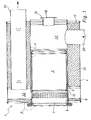
- the exhaust gas purification arrangement shown in FIGS. 1 to 4 an exhaust system of a motor vehicle comprises a Silencer 1 with integrated particle filter Second
- the muffler 1 is designed in shell construction and has a muffler housing 4 consisting of a circumferential mantle and axial end faces 6, 17.
- the muffler does not have any further interest here Items, such as a co-mated input pipe 29, a coaxial laterally offset output tube 30 and insulation material 31 for the formation of absorption chambers. Also the muffler has reflection chambers 32.
- the right in Figure 1 axial end face 17 has a central maintenance opening 18 with a peripheral flange 19 for Fixing a burner.
- the left in Figure 1 axial end face 6 has a central axial housing opening 5 for receiving a pot-like Removable housing 3.
- the removable housing 3 is in a form-fitting fit a particulate filter 2 arranged in the form of a monolithic ceramic filter.
- the open according to Figure 1 on the right axial side Removable housing 3 has a pot bottom 7 and a circumferential jacket.
- the pot bottom region of the removable housing 3 extends through the left axial housing opening 5 of the muffler housing 4th
- the removable housing 3 is in the region of the pot bottom 7 its periphery with the end face 6 of the muffler housing releasably connected.
- the pot bottom 7 of the removable housing 3 a radial peripheral flange 27, which at a radial Counter flange 28 on the front side 6 of the muffler housing 4 is screwed.
- the removable housing 3 extends in the axial direction of Silencer housing 4.
- the pot bottom 7 facing away from the other open end of the removable housing 3 is characterized by at least one muffler housing inner wall, preferably one of the removable housing. 3 enclosing housing inner shell 12 and a radial wall 13 with passage opening, supported.
- the open end of the removable housing 3 is an angular peripheral seal 14 radially and axially on the silencer housing inner walls supported, especially when screwed the change-over housing axially biased.
- a detachable Form fitting ring 15 used in the open end of the removable housing 3 in the open end of the removable housing 3 in the open end of the removable housing 3 is a detachable Form fitting ring 15 used.
- the Formpnutring 14 has a U-shaped cross section and is supported axially on the angle-circumferential seal 14.
- Preceded seal 16 Inside the removable housing 3 is another axial Preceded seal 16, which is preferably ceramic Particle filter 2 in the interior of the removable housing 3 axially fixed.
- the circumferential shell of the removable housing 3 is in the range of Saucepan 7 perforated.
- the interchangeable housing 3 including Particle filter 2 For disassembly of the removable housing 3 including Particle filter 2 are the screws of the flange mounting 27, 28 solved and the interchangeable housing plus content including Form fitting ring 15 and axial seal 16 axially from the muffler housing 4 through the end face 6 according to Drawing pulled out to the left. After a washout of the particulate filter 2, the interchangeable housing 3 including Particle filter 2 used again accordingly. Possibly is at a maintenance of the particulate filter. 2 this completely from the removable housing 3 by removing the Formpavyrings 15 and the axial seal 16 exposed.
- an exhaust gas purification arrangement substantially corresponds the embodiment of Figures 1 to 4, however, has instead of the local peripheral flange attachment a Tape clamp fastening on.
- the pot bottom 7 of the removable housing has 3 a computersserweittation 9, which via a band clamp 10th detachable with an extension 11 of the muffler housing is fastened, wherein the peripheral extension 9 of the pot bottom 7 and the extension 11 of the muffler housing are conformed to.
- the peripheral extension 9 and the band clamp 10 have a V-shaped cross section, and it is between the perimeter extension and the band clamp the conical extension 11 of the muffler housing releasably clamped.
- the band clamp 10 For disassembly, the band clamp 10 by opening a Screw loosened. Then the removable housing 3 together with Content pulled out of the muffler housing 4 and vice versa after maintenance of the particulate filter 2 be inserted into the muffler housing 4.
Landscapes
- Engineering & Computer Science (AREA)
- Chemical & Material Sciences (AREA)
- Combustion & Propulsion (AREA)
- Mechanical Engineering (AREA)
- General Engineering & Computer Science (AREA)
- Processes For Solid Components From Exhaust (AREA)
Abstract
Description
- Figur 1
- einen schematischen Axialschnitt durch eine Abgasreinigungsanordnung mit Wechselgehäuse und Partikelfilter in einer Ausführungsvariante,
- Figur 2
- die Abgasreinigungsanordnung nach Figur 1 in einer Stirnansicht,
- Figur 3
- die Einzelheit Z der Figur 1 in einer vergrößerten Darstellung,
- Figur 4
- die Einzelheit Y der Figur 1 in einer vergrößerten Darstellung, und
- Figuren 5 bis 8
- eine Abgasreinigungsanordnung in einer anderen Ausführungsvariante in Darstellungen entsprechend den Figuren 1 bis 4.
Claims (13)
- Abgasreinigungsanordnung einer Kraftfahrzeug-Abgasanlage, mit einem Schalldämpfer (1) in Mantelbauweise und einem integrierten Partikelfilter (2),
dadurch gekennzeichnet, daß der Partikelfilter (2) in einem topfartigen Wechselgehäuse (3) im Innern des Schalldämpfergehäuses (4) aufgenommen ist, wobei sich der Topfboden-Bereich des Wechselgehäuses durch eine axiale Gehäuseöffnung (5) in einer Stirnseite (6) des Schalldämpfergehäuses erstreckt und auf seinem Umfang mit der Stirnseite (6) des Schalldämpfergehäuses (4) lösbar verbunden ist. - Abgasreinigungsanordnung nach Anspruch 1,
dadurch gekennzeichnet, daß der Topfboden (7) des Wechselgehäuses (3) einen radialen Umfangsflansch (27) aufweist, welcher an einem radialen Gegenflansch (28) an der Stirnseite (6) des Schalldämpfergehäuses (4) schraubbefestigt ist. - Abgasreinigungsanordnung nach Anspruch 1,
dadurch gekennzeichnet, daß der Topfboden (7) des Wechselgehäuses (3) eine Umfangserweiterung (9) besitzt, welche über eine Bandschelle (10) mit einer Erweiterung (11) des Schalldämpfergehäuses (4) lösbar befestigt ist, wobei die Umfangserweiterung (9) des Topfbodens und die Erweiterung (11) des Schalldämpfergehäuses formangepaßt sind. - Abgasreinigungsanordnung nach Anspruch 3,
dadurch gekennzeichnet, daß die Umfangserweiterung (9) und die Bandschelle (10) V-förmigen Querschnitt besitzen, und zwischen Umfangserweiterung (9) und Bandschelle (10) eine konische Erweiterung (11) des Schalldämpfergehäuses (4) lösbar eingespannt ist. - Abgasreinigungsanordnung nach einem der Ansprüche 1 bis 4,
dadurch gekennzeichnet, daß sich das Wechselgehäuse (3) in Axialrichtung des Schalldämpfergehäuses (4) erstreckt. - Abgasreinigungsanordnung nach einem der Ansprüche 1 bis 5,
dadurch gekennzeichnet, daß das dem Topfboden (7) abgewandte andere offene Ende dessen Wechselgehäuses (3) durch zumindest eine Schalldämpfer-Gehäuseinnenwand, vorzugsweise einen das Wechselgehäuse umschließenden Gehäuseinnenmantel (12) und eine Radialwand (13) mit Durchgangsöffnung, abgestützt ist. - Abgasreinigungsanordnung nach Anspruch 6,
dadurch gekennzeichnet, daß das offene Ende des Wechselgehäuses (3) über eine Winkel-Umfangsabdichtung (14) radial und axial an den Schalldämpfer-Gehäuseinnenwänden abgestützt ist, insbesondere bei Schraub- oder Bandschellen-Befestigung des Wechselgehäuses (3) axial vorgespannt ist. - Abgasreinigungsanordnung nach Anspruch 6 oder 7,
dadurch gekennzeichnet, daß im offenen Ende des Wechselgehäuses (3) ein lösbarer Formpaßring (15) eingesetzt ist. - Abgasreinigungsanordnung nach Anspruch 8,
dadurch gekennzeichnet, daß der Formpaßring (15) einen U-förmigen Querschnitt besitzt. - Abgasreinigungsanordnung nach Anspruch 8 oder 9,
dadurch gekennzeichnet, daß der Formpaßring (15) sich axial an der Winkel-Umfangsabdichtung (14) abstützt. - Abgasreinigungsanordnung nach einem der Ansprüche 8 bis 10,
dadurch gekennzeichnet, daß im Innern des Wechselgehäuses (3) eine weitere axiale Dichtung (16) vorgelagert ist, welche den vorzugsweise keramischen Partikelfilter (2) im Innern des Wechselgehäuses axial fixiert. - Abgasreinigungsanordnung nach einem der Ansprüche 1 bis 11,
dadurch gekennzeichnet, daß der Umfangsmantel des Wechselgehäuses (3) im Bereich des Topfbodens (7) perforiert ist. - Abgasreinigungsanordnung nach einem der Ansprüche 1 bis 12,
dadurch gekennzeichnet, daß die dem Topfboden (7) des Wechselgehäuses (3) abgewandte andere Stirnseite (17) des Schalldämpfergehäuses (4) eine Wartungsöffnung (18) mit einem Befestigungsflansch (19) aufweist, an welchem ein Brenner für eine Partikelverbrennung im Innern des Schalldämpfers befestigbar ist.
Applications Claiming Priority (2)
| Application Number | Priority Date | Filing Date | Title |
|---|---|---|---|
| DE10144613A DE10144613A1 (de) | 2001-09-11 | 2001-09-11 | Abgasreinigungsanordnung einer Kraftfahrzeug-Abgasanlage |
| DE10144613 | 2001-09-11 |
Publications (2)
| Publication Number | Publication Date |
|---|---|
| EP1298289A1 true EP1298289A1 (de) | 2003-04-02 |
| EP1298289B1 EP1298289B1 (de) | 2005-04-06 |
Family
ID=7698560
Family Applications (1)
| Application Number | Title | Priority Date | Filing Date |
|---|---|---|---|
| EP02015880A Expired - Lifetime EP1298289B1 (de) | 2001-09-11 | 2002-07-17 | Abgasreinigungsanordnung einer Kraftfahrzeug-Abgasanlage |
Country Status (2)
| Country | Link |
|---|---|
| EP (1) | EP1298289B1 (de) |
| DE (2) | DE10144613A1 (de) |
Cited By (8)
| Publication number | Priority date | Publication date | Assignee | Title |
|---|---|---|---|---|
| GB2419635A (en) * | 2003-10-14 | 2006-05-03 | Fleetguard Inc | Muffler or silencer with readily removable end plate to allow access to an internal element requiring servicing |
| EP1701011A4 (de) * | 2003-11-27 | 2010-07-07 | Hino Motors Ltd | Abgasentgiftungsvorrichtung |
| WO2013167556A1 (de) * | 2012-05-11 | 2013-11-14 | Eberspächer Exhaust Technology GmbH & Co. KG | Partikelfilter |
| WO2014008930A1 (en) * | 2012-07-10 | 2014-01-16 | Swenox Ab | Apparatus for treating an exhaust gas stream with removable module |
| DE102015214765A1 (de) * | 2015-08-03 | 2017-02-09 | Mtu Friedrichshafen Gmbh | Wechseleinschubelement für eine Abgasnachbehandlungs-Anordnung, Abgasnachbehandlungs-Anordnung, Abgassystem und Brennkraftmaschine |
| EP3147472A1 (de) * | 2015-09-25 | 2017-03-29 | Eberspächer Exhaust Technology GmbH & Co. KG | Abgasnachbehandlungseinrichtung |
| CN113692482A (zh) * | 2019-04-23 | 2021-11-23 | 斯堪尼亚商用车有限公司 | 包括带螺纹的拆卸元件的排放控制装置 |
| US11268432B2 (en) | 2020-01-09 | 2022-03-08 | Purem GmbH | Exhaust system |
Families Citing this family (5)
| Publication number | Priority date | Publication date | Assignee | Title |
|---|---|---|---|---|
| DE102008031874B4 (de) * | 2008-07-05 | 2015-12-17 | Man Truck & Bus Ag | Abgasreinigungsvorrichtung für eine Brennkraftmaschine eines Fahrzeuges, insbesondere eines Nutzfahrzeuges sowie Anordnung einer Abgasreinigungsvorrichtung |
| DE102009012892B4 (de) * | 2009-03-12 | 2022-06-15 | Friedrich Boysen Gmbh & Co. Kg | Dieselpartikelfilteranordnung |
| DE102009014435A1 (de) | 2009-03-26 | 2010-10-14 | J. Eberspächer GmbH & Co. KG | Abgasbehandlungseinrichtung |
| CN105370346A (zh) * | 2015-12-17 | 2016-03-02 | 无锡威孚力达催化净化器有限责任公司 | 颗粒捕集器安装及拆卸结构 |
| CN112752896B (zh) * | 2018-10-09 | 2024-02-06 | 沃尔沃卡车集团 | 用于内燃机的排气系统的排气后处理装置 |
Citations (6)
| Publication number | Priority date | Publication date | Assignee | Title |
|---|---|---|---|---|
| US4264344A (en) * | 1980-02-06 | 1981-04-28 | General Motors Corporation | Diesel engine exhaust particulate trap |
| US4896503A (en) * | 1987-11-19 | 1990-01-30 | Alexandrex, Inc. | Muffling and purifying device for combustion gases of general application |
| US5139107A (en) * | 1990-12-11 | 1992-08-18 | Kioritz Corporation | Exhaust muffler for internal combustion engines |
| US5373119A (en) * | 1990-11-23 | 1994-12-13 | Kioritz Corporation | Exhaust muffler for internal combustion engine |
| WO1997005368A1 (en) * | 1995-06-30 | 1997-02-13 | Antoine Poppe | Filter for exhaust gases of a gasoline engine, respectively a diesel engine |
| WO1998040610A1 (en) * | 1997-03-13 | 1998-09-17 | The Associated Octel Company Limited | An engine exhaust system |
Family Cites Families (5)
| Publication number | Priority date | Publication date | Assignee | Title |
|---|---|---|---|---|
| DE3203237A1 (de) * | 1982-02-01 | 1983-08-11 | Knecht Filterwerke Gmbh, 7000 Stuttgart | Abgasfilter fuer verbrennungsmotoren |
| DE3832987A1 (de) * | 1988-09-29 | 1989-05-18 | Gerhard Fabritz | Schalldaempfer fuer verbrennungsmotoren |
| DE4130376A1 (de) * | 1991-09-12 | 1993-03-18 | Eberspaecher J | Vorrichtung zum entfernen von partikeln aus dieselmotorenabgas |
| DE9312405U1 (de) * | 1993-08-19 | 1993-10-21 | Heinrich Gillet Gmbh & Co Kg, 67480 Edenkoben | Abgasanlage für Verbrennungsmotoren |
| FR2735179A1 (fr) * | 1995-06-06 | 1996-12-13 | Chetwood International Sa | Perfectionnement pour dispositif d'echappement d'un moteur a combustion interne |
-
2001
- 2001-09-11 DE DE10144613A patent/DE10144613A1/de not_active Withdrawn
-
2002
- 2002-07-17 EP EP02015880A patent/EP1298289B1/de not_active Expired - Lifetime
- 2002-07-17 DE DE50202697T patent/DE50202697D1/de not_active Expired - Lifetime
Patent Citations (6)
| Publication number | Priority date | Publication date | Assignee | Title |
|---|---|---|---|---|
| US4264344A (en) * | 1980-02-06 | 1981-04-28 | General Motors Corporation | Diesel engine exhaust particulate trap |
| US4896503A (en) * | 1987-11-19 | 1990-01-30 | Alexandrex, Inc. | Muffling and purifying device for combustion gases of general application |
| US5373119A (en) * | 1990-11-23 | 1994-12-13 | Kioritz Corporation | Exhaust muffler for internal combustion engine |
| US5139107A (en) * | 1990-12-11 | 1992-08-18 | Kioritz Corporation | Exhaust muffler for internal combustion engines |
| WO1997005368A1 (en) * | 1995-06-30 | 1997-02-13 | Antoine Poppe | Filter for exhaust gases of a gasoline engine, respectively a diesel engine |
| WO1998040610A1 (en) * | 1997-03-13 | 1998-09-17 | The Associated Octel Company Limited | An engine exhaust system |
Cited By (20)
| Publication number | Priority date | Publication date | Assignee | Title |
|---|---|---|---|---|
| US7100736B2 (en) | 2003-10-14 | 2006-09-05 | Fleetguard, Inc. | Serviceable muffler |
| GB2419635B (en) * | 2003-10-14 | 2007-05-09 | Fleetguard Inc | Serviceable muffler |
| GB2419635A (en) * | 2003-10-14 | 2006-05-03 | Fleetguard Inc | Muffler or silencer with readily removable end plate to allow access to an internal element requiring servicing |
| EP1701011A4 (de) * | 2003-11-27 | 2010-07-07 | Hino Motors Ltd | Abgasentgiftungsvorrichtung |
| CN104271905B (zh) * | 2012-05-11 | 2017-05-10 | 埃贝斯佩歇废气技术合资公司 | 粒子过滤器及消音器 |
| WO2013167556A1 (de) * | 2012-05-11 | 2013-11-14 | Eberspächer Exhaust Technology GmbH & Co. KG | Partikelfilter |
| CN104271905A (zh) * | 2012-05-11 | 2015-01-07 | 埃贝斯佩歇废气技术合资公司 | 粒子过滤器 |
| JP2015517619A (ja) * | 2012-05-11 | 2015-06-22 | エーバーシュペッヒャー・エグゾースト・テクノロジー・ゲーエムベーハー・ウント・コンパニー・カーゲー | 粒子フィルター |
| RU2599094C2 (ru) * | 2012-05-11 | 2016-10-10 | Эбершпехер Игзост Текнолоджи Гмбх Унд Ко. Кг | Фильтр частиц |
| US9540976B2 (en) | 2012-05-11 | 2017-01-10 | Eberspächer Exhaust Technology GmbH & Co. KG | Particle filter |
| WO2014008930A1 (en) * | 2012-07-10 | 2014-01-16 | Swenox Ab | Apparatus for treating an exhaust gas stream with removable module |
| DE102015214765A1 (de) * | 2015-08-03 | 2017-02-09 | Mtu Friedrichshafen Gmbh | Wechseleinschubelement für eine Abgasnachbehandlungs-Anordnung, Abgasnachbehandlungs-Anordnung, Abgassystem und Brennkraftmaschine |
| DE102015214765B4 (de) | 2015-08-03 | 2025-10-02 | Rolls-Royce Solutions GmbH | Abgasnachbehandlungs-Anordnung, Abgassystem und Brennkraftmaschine |
| US20170089249A1 (en) * | 2015-09-25 | 2017-03-30 | Eberspächer Exhaust Technology GmbH & Co. KG | Exhaust gas treatment device |
| EP3147472A1 (de) * | 2015-09-25 | 2017-03-29 | Eberspächer Exhaust Technology GmbH & Co. KG | Abgasnachbehandlungseinrichtung |
| CN107035497A (zh) * | 2015-09-25 | 2017-08-11 | 埃贝斯佩歇废气技术合资公司 | 废气后处理装置 |
| US10294847B2 (en) | 2015-09-25 | 2019-05-21 | Eberspächer Exhaust Technology GmbH & Co. KG | Exhaust gas treatment device |
| CN107035497B (zh) * | 2015-09-25 | 2019-08-30 | 埃贝斯佩歇废气技术合资公司 | 废气后处理装置 |
| CN113692482A (zh) * | 2019-04-23 | 2021-11-23 | 斯堪尼亚商用车有限公司 | 包括带螺纹的拆卸元件的排放控制装置 |
| US11268432B2 (en) | 2020-01-09 | 2022-03-08 | Purem GmbH | Exhaust system |
Also Published As
| Publication number | Publication date |
|---|---|
| DE50202697D1 (de) | 2005-05-12 |
| EP1298289B1 (de) | 2005-04-06 |
| DE10144613A1 (de) | 2003-04-03 |
Similar Documents
| Publication | Publication Date | Title |
|---|---|---|
| EP1298289B1 (de) | Abgasreinigungsanordnung einer Kraftfahrzeug-Abgasanlage | |
| EP1691045B1 (de) | Abgasreinigungssystem | |
| DE69507728T2 (de) | Verfahren und Vorrichtung zur Behandlung von Abgasen | |
| DE19959955C2 (de) | Vorrichtung zur Reinigung der Abgase eines Verbrennungsmotors | |
| DE60212351T2 (de) | Abgasreinigungsvorrichtung | |
| EP2261475B1 (de) | Abgasreinigungseinrichtung | |
| DE10296366B4 (de) | Reinigungsfähige Vorrichtung zur Schadstoffbeseitigung in Motorabgasen | |
| US4709549A (en) | Assembly for engine exhaust gas particulate filter traps | |
| DE60304339T2 (de) | Reinigbare vorrichtung zur entgiftung von motorabgasen | |
| EP0191437A1 (de) | Vorrichtung und Verfahren zum Beseitigen von Russ o. dgl. aus den Abgasen einer Brennkraftmaschine | |
| WO2013167556A1 (de) | Partikelfilter | |
| DE3883746T2 (de) | Abgasvorrichtung mit russfilter für eine brennkraftmaschine. | |
| EP0212396A2 (de) | Vorrichtung zum Beseitigen von Russ o. dgl. ausden Abgasen einer Brennkraftmaschine | |
| DE10216272B4 (de) | Abgasbehandlungsanordnung für eine Brennkraftmaschine | |
| EP0357595B1 (de) | Abgasreinigungsvorrichtung für dieselmotoren | |
| EP0511415A1 (de) | Filtereinrichtung und Verfahren zur Abgasreinigung durch Filtration | |
| DE10202005B4 (de) | Filtereinrichtung | |
| DE4207005A1 (de) | Abgasreiniger | |
| DE102004013786A1 (de) | Abgasnachbehandlungssystem für ein Kraftfahrzeug | |
| DE102008032766A1 (de) | Vorrichtung zum Reinigen der Abgase von Dieselmotoren | |
| EP1767752B1 (de) | Abgasbehandlungseinrichtung | |
| EP0693616A1 (de) | Vorrichtung zur katalytischen Reinigung bzw. Zerlegung von heissen Agbasen | |
| DE102009034085A1 (de) | Abgasanlage | |
| EP0326659B1 (de) | Regenerierbarer Russfilter für das Abgas von Verbrennungsmotoren | |
| AT500745A4 (de) | Abgasreinigungsvorrichtung |
Legal Events
| Date | Code | Title | Description |
|---|---|---|---|
| PUAI | Public reference made under article 153(3) epc to a published international application that has entered the european phase |
Free format text: ORIGINAL CODE: 0009012 |
|
| AK | Designated contracting states |
Kind code of ref document: A1 Designated state(s): AT BE BG CH CY CZ DE DK EE ES FI FR GB GR IE IT LI LU MC NL PT SE SK TR Designated state(s): AT BE BG CH CY CZ DE DK EE ES FI FR GB GR IE IT LI LU MC NL PT SE SK TR |
|
| AX | Request for extension of the european patent |
Extension state: AL LT LV MK RO SI |
|
| 17P | Request for examination filed |
Effective date: 20030211 |
|
| 17Q | First examination report despatched |
Effective date: 20030519 |
|
| AKX | Designation fees paid |
Designated state(s): DE FR GB IT SE |
|
| GRAP | Despatch of communication of intention to grant a patent |
Free format text: ORIGINAL CODE: EPIDOSNIGR1 |
|
| GRAS | Grant fee paid |
Free format text: ORIGINAL CODE: EPIDOSNIGR3 |
|
| GRAA | (expected) grant |
Free format text: ORIGINAL CODE: 0009210 |
|
| AK | Designated contracting states |
Kind code of ref document: B1 Designated state(s): DE FR GB IT SE |
|
| REG | Reference to a national code |
Ref country code: GB Ref legal event code: FG4D Free format text: NOT ENGLISH |
|
| REG | Reference to a national code |
Ref country code: IE Ref legal event code: FG4D Free format text: LANGUAGE OF EP DOCUMENT: GERMAN |
|
| REF | Corresponds to: |
Ref document number: 50202697 Country of ref document: DE Date of ref document: 20050512 Kind code of ref document: P |
|
| REG | Reference to a national code |
Ref country code: SE Ref legal event code: TRGR |
|
| GBT | Gb: translation of ep patent filed (gb section 77(6)(a)/1977) |
Effective date: 20050608 |
|
| PLBE | No opposition filed within time limit |
Free format text: ORIGINAL CODE: 0009261 |
|
| STAA | Information on the status of an ep patent application or granted ep patent |
Free format text: STATUS: NO OPPOSITION FILED WITHIN TIME LIMIT |
|
| ET | Fr: translation filed | ||
| 26N | No opposition filed |
Effective date: 20060110 |
|
| REG | Reference to a national code |
Ref country code: FR Ref legal event code: PLFP Year of fee payment: 14 |
|
| REG | Reference to a national code |
Ref country code: FR Ref legal event code: PLFP Year of fee payment: 15 |
|
| REG | Reference to a national code |
Ref country code: FR Ref legal event code: PLFP Year of fee payment: 16 |
|
| PGFP | Annual fee paid to national office [announced via postgrant information from national office to epo] |
Ref country code: IT Payment date: 20170721 Year of fee payment: 16 |
|
| REG | Reference to a national code |
Ref country code: FR Ref legal event code: PLFP Year of fee payment: 17 |
|
| REG | Reference to a national code |
Ref country code: DE Ref legal event code: R081 Ref document number: 50202697 Country of ref document: DE Owner name: PUREM GMBH, DE Free format text: FORMER OWNER: J. EBERSPAECHER GMBH & CO. KG, 73730 ESSLINGEN, DE Ref country code: DE Ref legal event code: R081 Ref document number: 50202697 Country of ref document: DE Owner name: EBERSPAECHER EXHAUST TECHNOLOGY GMBH & CO. KG, DE Free format text: FORMER OWNER: J. EBERSPAECHER GMBH & CO. KG, 73730 ESSLINGEN, DE |
|
| REG | Reference to a national code |
Ref country code: GB Ref legal event code: 732E Free format text: REGISTERED BETWEEN 20181220 AND 20181224 |
|
| PG25 | Lapsed in a contracting state [announced via postgrant information from national office to epo] |
Ref country code: IT Free format text: LAPSE BECAUSE OF NON-PAYMENT OF DUE FEES Effective date: 20180717 |
|
| REG | Reference to a national code |
Ref country code: DE Ref legal event code: R082 Ref document number: 50202697 Country of ref document: DE Representative=s name: RUTTENSPERGER LACHNIT TROSSIN GOMOLL, PATENT- , DE Ref country code: DE Ref legal event code: R081 Ref document number: 50202697 Country of ref document: DE Owner name: PUREM GMBH, DE Free format text: FORMER OWNER: EBERSPAECHER EXHAUST TECHNOLOGY GMBH & CO. KG, 66539 NEUNKIRCHEN, DE |
|
| REG | Reference to a national code |
Ref country code: GB Ref legal event code: 732E Free format text: REGISTERED BETWEEN 20210902 AND 20210908 |
|
| PGFP | Annual fee paid to national office [announced via postgrant information from national office to epo] |
Ref country code: FR Payment date: 20210721 Year of fee payment: 20 |
|
| PGFP | Annual fee paid to national office [announced via postgrant information from national office to epo] |
Ref country code: GB Payment date: 20210722 Year of fee payment: 20 Ref country code: SE Payment date: 20210721 Year of fee payment: 20 Ref country code: DE Payment date: 20210721 Year of fee payment: 20 |
|
| REG | Reference to a national code |
Ref country code: DE Ref legal event code: R071 Ref document number: 50202697 Country of ref document: DE |
|
| REG | Reference to a national code |
Ref country code: GB Ref legal event code: PE20 Expiry date: 20220716 |
|
| REG | Reference to a national code |
Ref country code: SE Ref legal event code: EUG |
|
| PG25 | Lapsed in a contracting state [announced via postgrant information from national office to epo] |
Ref country code: GB Free format text: LAPSE BECAUSE OF EXPIRATION OF PROTECTION Effective date: 20220716 |