EP1298264A2 - Back-pull drive for a conservatory awning - Google Patents
Back-pull drive for a conservatory awning Download PDFInfo
- Publication number
- EP1298264A2 EP1298264A2 EP02021496A EP02021496A EP1298264A2 EP 1298264 A2 EP1298264 A2 EP 1298264A2 EP 02021496 A EP02021496 A EP 02021496A EP 02021496 A EP02021496 A EP 02021496A EP 1298264 A2 EP1298264 A2 EP 1298264A2
- Authority
- EP
- European Patent Office
- Prior art keywords
- carriage
- fixed
- counter
- toothed
- toothed belt
- Prior art date
- Legal status (The legal status is an assumption and is not a legal conclusion. Google has not performed a legal analysis and makes no representation as to the accuracy of the status listed.)
- Withdrawn
Links
Images


Classifications
-
- E—FIXED CONSTRUCTIONS
- E06—DOORS, WINDOWS, SHUTTERS, OR ROLLER BLINDS IN GENERAL; LADDERS
- E06B—FIXED OR MOVABLE CLOSURES FOR OPENINGS IN BUILDINGS, VEHICLES, FENCES OR LIKE ENCLOSURES IN GENERAL, e.g. DOORS, WINDOWS, BLINDS, GATES
- E06B9/00—Screening or protective devices for wall or similar openings, with or without operating or securing mechanisms; Closures of similar construction
- E06B9/56—Operating, guiding or securing devices or arrangements for roll-type closures; Spring drums; Tape drums; Counterweighting arrangements therefor
- E06B9/62—Counterweighting arrangements
-
- E—FIXED CONSTRUCTIONS
- E04—BUILDING
- E04F—FINISHING WORK ON BUILDINGS, e.g. STAIRS, FLOORS
- E04F10/00—Sunshades, e.g. Florentine blinds or jalousies; Outside screens; Awnings or baldachins
- E04F10/02—Sunshades, e.g. Florentine blinds or jalousies; Outside screens; Awnings or baldachins of flexible canopy materials, e.g. canvas ; Baldachins
- E04F10/06—Sunshades, e.g. Florentine blinds or jalousies; Outside screens; Awnings or baldachins of flexible canopy materials, e.g. canvas ; Baldachins comprising a roller-blind with means for holding the end away from a building
- E04F10/0607—Sunshades, e.g. Florentine blinds or jalousies; Outside screens; Awnings or baldachins of flexible canopy materials, e.g. canvas ; Baldachins comprising a roller-blind with means for holding the end away from a building with guiding-sections for supporting the movable end of the blind
-
- E—FIXED CONSTRUCTIONS
- E04—BUILDING
- E04F—FINISHING WORK ON BUILDINGS, e.g. STAIRS, FLOORS
- E04F10/00—Sunshades, e.g. Florentine blinds or jalousies; Outside screens; Awnings or baldachins
- E04F10/02—Sunshades, e.g. Florentine blinds or jalousies; Outside screens; Awnings or baldachins of flexible canopy materials, e.g. canvas ; Baldachins
- E04F10/06—Sunshades, e.g. Florentine blinds or jalousies; Outside screens; Awnings or baldachins of flexible canopy materials, e.g. canvas ; Baldachins comprising a roller-blind with means for holding the end away from a building
- E04F10/0644—Sunshades, e.g. Florentine blinds or jalousies; Outside screens; Awnings or baldachins of flexible canopy materials, e.g. canvas ; Baldachins comprising a roller-blind with means for holding the end away from a building with mechanisms for unrolling or balancing the blind
- E04F10/0648—Sunshades, e.g. Florentine blinds or jalousies; Outside screens; Awnings or baldachins of flexible canopy materials, e.g. canvas ; Baldachins comprising a roller-blind with means for holding the end away from a building with mechanisms for unrolling or balancing the blind acting on the roller tube
-
- E—FIXED CONSTRUCTIONS
- E04—BUILDING
- E04F—FINISHING WORK ON BUILDINGS, e.g. STAIRS, FLOORS
- E04F10/00—Sunshades, e.g. Florentine blinds or jalousies; Outside screens; Awnings or baldachins
- E04F10/02—Sunshades, e.g. Florentine blinds or jalousies; Outside screens; Awnings or baldachins of flexible canopy materials, e.g. canvas ; Baldachins
- E04F10/06—Sunshades, e.g. Florentine blinds or jalousies; Outside screens; Awnings or baldachins of flexible canopy materials, e.g. canvas ; Baldachins comprising a roller-blind with means for holding the end away from a building
- E04F10/0644—Sunshades, e.g. Florentine blinds or jalousies; Outside screens; Awnings or baldachins of flexible canopy materials, e.g. canvas ; Baldachins comprising a roller-blind with means for holding the end away from a building with mechanisms for unrolling or balancing the blind
- E04F10/0655—Sunshades, e.g. Florentine blinds or jalousies; Outside screens; Awnings or baldachins of flexible canopy materials, e.g. canvas ; Baldachins comprising a roller-blind with means for holding the end away from a building with mechanisms for unrolling or balancing the blind acting on the movable end, e.g. front bar
-
- E—FIXED CONSTRUCTIONS
- E04—BUILDING
- E04F—FINISHING WORK ON BUILDINGS, e.g. STAIRS, FLOORS
- E04F10/00—Sunshades, e.g. Florentine blinds or jalousies; Outside screens; Awnings or baldachins
- E04F10/02—Sunshades, e.g. Florentine blinds or jalousies; Outside screens; Awnings or baldachins of flexible canopy materials, e.g. canvas ; Baldachins
- E04F10/06—Sunshades, e.g. Florentine blinds or jalousies; Outside screens; Awnings or baldachins of flexible canopy materials, e.g. canvas ; Baldachins comprising a roller-blind with means for holding the end away from a building
- E04F10/0685—Covers or housings for the rolled-up blind
Definitions
- the invention is concerned with a balancing system for adjustment a curtain of a conservatory awning, which between a winding shaft and a movable fall profile arranged is that with its lateral ends on a carriage or slider that is set in side guides run and on each of which a flexible tension element is fixed is, each between the two ends of the car or ladder, drive plates driving them positively and deflection rollers are formed all around.
- Such a counter-pull system with a continuous endless toothed belt is for example from DE 199 14 543.1 and the US 5 035 091 known.
- a revolving tension element has already been proposed, so that the disadvantages of being wound on the drive shaft Tension element with the changing diameter be avoided.
- elaborate solution of the length compensation arise Problems with rotating, form-fitting with the drive plates interacting tension elements initially during assembly, because the two timing belts on the respective carriage must be set securely and for safe transportation through the drive plate, for example, a certain voltage a timing belt must be adjusted to prevent slipping to prevent safely.
- this solution offers advantages when installing the conserveatory awning because the pulling element, for example, has no problems first fixed to the carriage, then over the drive plate and guided the pulley and finally with his other end can also be fixed to the car. Differences in length, such as. B. by dimensional deviations or Inaccuracies in assembly can occur easily compensated by the choice of the length of the toothed belt become.
- an endless traction element closed as a ring, for example a timing belt there are cost advantages also in that the tension element is manufactured by the meter and can be processed while up to now for each extension length a special order was necessary, which in particular Considerable production costs for systems with very long extension lengths entailed.
- the object of the present invention is a counter-pull system to create that with positively carried Tension elements an improved position of the fall profile allows.
- the object is achieved in that at least one end of the traction element steplessly to the car or Gliders can be set in different length positions and / or at least one of those driven by a motor Drive shaft seated drive disks continuously can be fixed in different angular positions on the drive shaft is.
- individually or in Combination can smoothly compensate for differences in length be so that by setting the timing belt ends in corresponding serrations on the carriage or glider and the associated adjustment only possible step by step and both carriages or gliders are exactly the same Length position are adjustable.
- This is also an absolute exact fine adjustment of the case profile possible, so that optically conspicuous malpositions are no longer tolerated must and still have the advantages of a form-fitting Take away can be used. It is also possible to get an optimal one Preloading, for example, a toothed belt as a tension element to be able to adjust so that one under all circumstances given positive locking without the risk of slipping is guaranteed.
- Timing belts are light, relative inexpensive and enable a secure form fit. Basically, however, is the use of a chain or of a perforated belt is conceivable as a tension element, the driving pulleys then accordingly as a gear or pin disc are trained.
- the tension elements made entirely of timing belts
- the traction elements partly made of toothed belts, between the car or glider and intermediate elements are arranged and over the trained as toothed disks Drive plate run, and otherwise as simple tension elements, z. B. formed as a ribbon, rope, cord or the like are that between the intermediate elements and the carriage are provided and run over the pulleys.
- tension elements are possible because between the two End positions of the fall profile only part of the tension elements runs over the drive pulleys while in the area of the pulleys no positive entrainment is necessary.
- a particularly secure permanent hold results from a preferred embodiment, in which the ends of the tension elements form-fitting on the carriage and / or the intermediate elements are set. Compared to pure clamp connections it prevents the connection from changing over time can loosen or at least adjust, so that under certain circumstances a decrease in the desired tension of the toothed belt would be feared.
- An embodiment is particularly preferred in which each at least one end of the toothed belt by a corresponding one Tooth on the carriage or glider or on one the carriage or glider lockable locking element is held. Doing so will be particularly easy Meadow the conditions of the timing belt for positive Determination used.
- the toothing on the flank of a Slot in the carriage or glider, in which the toothed belt end to be fixed can be inserted laterally, the teeth of the toothed belt come into the toothing.
- the slot preferably has about a height that an insertion of the timing belt end in the longitudinal direction, with the in the toothing indented toothed belt remaining gap by a locking element is lockable. To prevent a side Slipping out of the slot is conveniently on the side by the locking element or another fixable on the car Lockable element.
- An alternative way of fastening the toothed belt end can be that the timing belt with the help of a Toothed locking element can be fixed to the car is.
- the closing element is preferably with screwed to the carriage or glider.
- the drive plates usually sit on one of one Motor driven drive shaft, on which preferably the winding shaft is spring-mounted in the direction of rotation. hereby length compensation in a space-saving way created by the different Winding diameter of the winding shaft in the different extension states results.
- the rotationally secure fixing of the drive plate can, for example be realized with the help of clamping screws, while preferably a thread adjustment between the Driving plate and the drive shaft for stepless adjustment the relative angular position is provided.
- the thread adjustment essentially a screw or a set screw, the shaft is aligned in the circumferential direction and the one hand on the Driver element or axially supported with respect to the drive shaft while their threaded shank is in one on top of the other Part engages axially fixed hollow thread.
- the clamping screws can be loosened changed the angular position by turning the screw and by subsequently tightening the clamping screws the torsionally rigid lock in the desired position be accomplished.
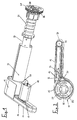
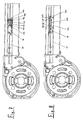
- Fig. 1 is a counter-pull system using the example of a conservatory awning 10 shown.
- This has a housing 12 whose two flanks guide rails 14 are provided in which slider 16 are guided in sliding guides on which the ends of a case profile 18 are fixed.
- glides trolleys with guide rollers can also be provided.
- An awning fabric 20 is fixed to the fall profile 18 and can be wound onto a winding or cloth shaft 22.
- the winding shaft 22 is designed as a hollow shaft and encloses one drive shaft 24 driven by a motor, one between the drive shaft 24 and the winding shaft 22 arranged preloaded torsion spring mechanism 26 for a structure a necessary bias of the awning fabric 20 and ensures length compensation when extending the awning, because the effective diameter when unwinding the awning cover 20 changes from the winding shaft 22.
- the drive shaft 24 is seated as a toothed disk 28 trained drive plate that drives the counter-pull system, its structure from the simplified view in FIG. 2 can be seen in more detail. There you can see that the toothed washer 28 is wrapped by a toothed belt 30, the two Has ends 32, 34, both of which are form-fitting on the slider 16 are set.
- the toothed belt 30 is used to form the counter-pull system formed all around and on a deflection roller 36 which in one Head part 38 at the head ends of the guide rails 14 is rotatably mounted.
- the slider 16 is simplified in FIG. 2 shown and preferably are similar to Fig. 3 pulleys provided in the area of the housing 12 for a targeted removal of the toothed belt 30 into the guide rail 14 at the level of the guide roller 36 or the height of the Ensure attachment point on slider 16.
- FIG. 3 shows an alternative embodiment, firstly on the previously mentioned deflection roller 40 in the lower area of the housing 12 and a further deflection roller 42 in the area of the upper exit point of the toothed belt is pointed out from the housing 12.
- the tension element 44 only partially from a guided over the drive plate 28 Toothed belt 46 exists, which is fixed to an intermediate element 48 is from where the revolving tension element 44 through a simple textile belt 50 is continued, which has a toothless Deflection roller 52 deflected and using a clamping device 54 fixed to the carriage 16 designed as a glider is.
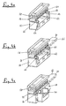
- 4 a - h shows the step-by-step determination of the toothed belt 30 on the slider sliding in the guide rail 14 16 described.
- 4 a is an oblique view of a Base body 56 of the slider 16 shown.
- the basic body 56 has an open at the top Slot 58, on the underside of which a toothing 60 is provided is to engage in the toothing of the toothed belt 30 is determined.
- the height of the slot 58 is chosen so that with a correspondingly raised end of the toothed belt Insertion in the longitudinal direction is made possible.
- the base body 56 has a further opening 62 with two side webs 64, the top of which as a toothing 66 is formed. As shown in Fig.
- the toothed belt is then moved over the toothed pulley 28, over the deflection roller 40 and over the deflection roller 36 in the head part 38 out and its second end 32 in the slot 58th introduced.
- the desired timing belt tension 30 is the tooth flank of the toothed belt 30 in the toothing 60 placed and a locking element from the front inserted the remaining space between the back 66 of the toothed belt 30 and the top of the slot 58 fills in, so that the toothed belt is held in the toothing 60 is.
- Locking element 76 fixed on the base body 56 of the slider 16. A possibly protruding part of the toothed belt 30 can now be cut off.
- a slot is without Gearing provided, with the help of a clamping insert 54 and clamping screws 78 jamming the free end of the Textile tape 50 on the base body 56 of the slider 16 allows is.
- Fig. 4 h shows the final installation position of the slider in the indicated guide rail 14.
- the thread adjustment 90 consists essentially of an adjusting screw 92, which is held axially on a head bearing 94, that rotates in a bore in the drive plate 28 sitting.
- the shaft of the set screw 92 is essentially in Direction of rotation aligned and engages with his head to an abutment 96 on the flange element 82.
- the direction of pressure is adjusted by the axial infeed the one sitting in a hollow thread in the head bearing 94 Set screw 92 while moving in the opposite direction done by the spring mechanism 26, which between the Drive shaft 24 and the winding shaft 22 seated over the awning fabric 20, the fall profile 18, the carriage 16 and the toothed belt 30 acts on the drive plate 28.
- the self-locking the adjusting screw 92 prevents adjustment under the effect of spring force.
- the adjustment mechanism shown in Fig. 5 is in its application not to the example of a conservatory awning described above limited, but can in principle also be used in other applications where an exact Angle of rotation alignment of a toothed disc or the like with respect to their bearing shaft is necessary.
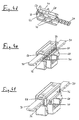
- FIG. 7 is a view of a counter-pull system similar to FIG. 3, in which case an adjusting device 100 is provided in the area of the slider 16, alternatively or in addition to the setting device shown in FIG. 5 make a fine adjustment of the toothed belt 30 can, for example, the case profile 18 to an exact to be able to adjust the aligned position and possibly also the To be able to adjust the pretension of the toothed belt 30.
- the adjustment device 100 consists essentially of a holding part 102 and a clamping piece 104, which with the aid of clamping screws 106 in a certain axial position to each other are jammed.
- the holding part 102 or the clamping piece 104 are firmly connected to the slider 16 and the two ends of the toothed belt 30 are fixed on the one hand on the slider 16 and on the other hand on the not connected to the slider 16 and after loosening the clamping screws 106 axially movable part, d. H. the holding part 102 or the clamping piece 104 connected.
- the toothed belt ends can be fixed, for example in a previously described manner.
- the adjustability of the holding part 102 and the clamping piece 104 to each other with the help of elongated holes 108 in the holding part 102 enables through which the shafts of the clamping screws 106 protrude. After loosening the clamping screws 106 can the holding part 102 and the clamping piece 104 to each other continuously be moved so that the desired setting of the Timing belt can be made.
- the length of the elongated holes 108 preferably corresponds at least to the tooth spacing of the Timing belt 30, even better double the tooth spacing, to be sufficient To offer adjustment.
- FIG. 8 Another embodiment of an adjusting device for stepless adjustment of the toothed belt 30 is shown in FIG. 8, the counter-pull system in the rest of that in Fig. 7 and also the embodiment shown in FIG. 3 essentially equivalent.
- the adjusting device 200 in turn has a holding part 202 firmly connected to the slider 16 and a axially movable with respect to the slider and the holding part 202 Actuator 204.
- the first end of the timing belt is fixed directly to the slider 16, the second end of the Timing belt 30 firmly connected to the actuator 204, so that again by an axial relative movement of the two parts to each other made the fine adjustment of the timing belt can be.
- the definition of the toothed belt ends as such the corresponding parts can be in the manner described above and way.
- the actuator 204 lies between two projections 205, which are integrally formed on the holding part 202 are.
- Two set screws 206, 207 extend axially through threaded holes in these projections 205 and act directly on the front flanks of the Actuator 204.
- the adjustment devices 100 or 200 with an adjustment device in the area of the pulleys can be combined if extended setting options be required. In principle, however, provision is sufficient an adjusting device in the area of the pulleys or the glider on one side of the balancer to move the to be able to make the desired setting options. both sides Adjustment devices can then be useful albeit the pretension of the toothed belt 30 on both sides with the help of the adjustment devices should.
Abstract
Description
Die Erfindung befaßt sich mit einem Gegenzugsystem zum Verstellen eines Behangs einer Wintergartenmarkise, der zwischen einer Wickelwelle und einem verfahrbaren Fallprofil angeordnet ist, das mit seinen seitlichen Enden jeweils an einem Wagen oder Gleiter festgelegt ist, die in seitlichen Führungen laufen und an welchen jeweils ein flexibles Zugelement festgelegt ist, die jeweils zwischen den beiden Enden der Wagen oder Leiter, sie formschlüssig antreibenden Mitnehmerscheiben und Umlenkrollen umlaufend ausgebildet sind.The invention is concerned with a balancing system for adjustment a curtain of a conservatory awning, which between a winding shaft and a movable fall profile arranged is that with its lateral ends on a carriage or slider that is set in side guides run and on each of which a flexible tension element is fixed is, each between the two ends of the car or ladder, drive plates driving them positively and deflection rollers are formed all around.
Ein derartiges Gegenzugsystem mit umlaufendem endlosem Zahnriemen ist beispielsweise aus der DE 199 14 543.1 und der US 5 035 091 bekannt. Bei dem dort beschriebenen Gegenzugsystem ist bereits ein umlaufendes Zugelement vorgeschlagen worden, so daß die Nachteile eines auf der Antriebswelle aufgewickelten Zugelements mit dem sich dadurch ändernden Durchmesser vermieden werden. Abgesehen von der in dieser Schrift gewählten aufwendigen Lösung des Längenausgleiches ergeben sich Probleme bei umlaufenden, formschlüssig mit den Mitnehmerscheiben zusammenwirkenden Zugelementen zunächst bei der Montage, da die beiden Zahnriemen an dem jeweils zugehörigen Wagen sicher festgelegt werden müssen und zur sicheren Mitnahme durch die Mitnehmerscheibe eine bestimmte Spannung beispielsweise eines Zahnriemens eingestellt werden muß, um ein Durchrutschen sicher zu verhindern.Such a counter-pull system with a continuous endless toothed belt is for example from DE 199 14 543.1 and the US 5 035 091 known. With the counter-pull system described there a revolving tension element has already been proposed, so that the disadvantages of being wound on the drive shaft Tension element with the changing diameter be avoided. Apart from the one chosen in this document elaborate solution of the length compensation arise Problems with rotating, form-fitting with the drive plates interacting tension elements initially during assembly, because the two timing belts on the respective carriage must be set securely and for safe transportation through the drive plate, for example, a certain voltage a timing belt must be adjusted to prevent slipping to prevent safely.
Aus der DE 199 63 862 A1 ist es auch bereits bekannt, daß bei einem Gegenzugsystem der eingangs beschriebenen Art die Zugelemente jeweils zwei freie Enden aufweisen, die unabhängig voneinander an dem jeweiligen Wagen festgelegt sind.From DE 199 63 862 A1 it is also known that at a traction system of the type described in the introduction the traction elements each have two free ends that are independent are fixed from each other on the respective car.
Zunächst bietet diese Lösung Vorteile bei der Montage der Wintergartenmarkise, da das Zugelement problemlos beispielsweise zunächst am Wagen festgelegt, dann über die Mitnehmerscheibe und die Umlenkrolle geführt und abschließend mit seinem anderen Ende ebenfalls am Wagen festgelegt werden kann. Längenunterschiede, wie sie z. B. durch Maßabweichungen oder Ungenauigkeiten bei der Montage auftreten können, können durch die Wahl der Länge des Zahnriemens leicht kompensiert werden. Gegenüber einem endlosen, als Ring geschlossenen Zugelement, beispielsweise einem Zahnriemen, bestehen Kostenvorteile auch darin, daß das Zugelement als Meterware gefertigt und verarbeitet werden kann, während bisher für jede Ausfahrlänge eine Sonderanfertigung notwendig war, was insbesondere bei Anlagen mit sehr großen Ausfahrlängen erhebliche Produktionskosten nach sich zog.First of all, this solution offers advantages when installing the Conservatory awning because the pulling element, for example, has no problems first fixed to the carriage, then over the drive plate and guided the pulley and finally with his other end can also be fixed to the car. Differences in length, such as. B. by dimensional deviations or Inaccuracies in assembly can occur easily compensated by the choice of the length of the toothed belt become. Compared to an endless traction element closed as a ring, for example a timing belt, there are cost advantages also in that the tension element is manufactured by the meter and can be processed while up to now for each extension length a special order was necessary, which in particular Considerable production costs for systems with very long extension lengths entailed.
Eine solche Lösung besitzt jedoch immer noch den Nachteil, daß bei formschlüssig mitgenommenen Zugelementen die Rasterung durch die Zahnabstände oder Lochabstände zu grob ist, um eine korrekte Ausrichtung des Fallprofils zu erreichen.However, such a solution still has the disadvantage that with positively entrained traction elements, the grid is too coarse due to the tooth spacing or hole spacing to achieve a correct alignment of the case profile.
Die Aufgabe der vorliegenden Erfindung besteht darin, ein Gegenzugsystem zu schaffen, das bei formschlüssig mitgenommenen Zugelementen eine verbesserte Lageeinstellung des Fallprofils ermöglicht.The object of the present invention is a counter-pull system to create that with positively carried Tension elements an improved position of the fall profile allows.
Erfindungsgemäß wird die Aufgabe dadurch gelöst, daß wenigstens ein Ende des Zugelements stufenlos an den Wagen oder Gleitern in unterschiedlichen Längenpositionen festlegbar ist und/oder wenigstens eine der auf einer von einem Motor angetriebenen Antriebswelle sitzenden Mitnehmerscheiben stufenlos in verschiedenen Winkellagen auf der Antriebswelle festlegbar ist. Durch diese erfindungsgemäßen Maßnahmen einzeln oder in Kombination können stufenlos Längendifferenzen ausgeglichen werden, so daß die durch die Festlegung der Zahnriemenenden in entsprechenden Verzahnungen am Wagen oder Gleiter und die damit einhergehende nur schrittweise mögliche Verstellung ergänzt wird und beide Wagen bzw. Gleiter exakt auf die gleiche Längenposition einstellbar sind. Damit ist auch eine absolut exakte Feineinstellung des Fallprofils möglich, so daß optisch auffällige Fehlstellungen nicht mehr hingenommen werden müssen und dennoch die Vorteile einer formschlüssigen Mitnahme genutzt werden können. Ferner ist möglich, eine optimale Vorspannung beispielsweise eines Zahnriemens als Zugelement einstellen zu können, so daß ein unter allen Umständen gegebener Formschluß ohne die Gefahr eines Durchrutschens gewährleistet ist.According to the invention the object is achieved in that at least one end of the traction element steplessly to the car or Gliders can be set in different length positions and / or at least one of those driven by a motor Drive shaft seated drive disks continuously can be fixed in different angular positions on the drive shaft is. Through these measures according to the invention individually or in Combination can smoothly compensate for differences in length be so that by setting the timing belt ends in corresponding serrations on the carriage or glider and the associated adjustment only possible step by step and both carriages or gliders are exactly the same Length position are adjustable. This is also an absolute exact fine adjustment of the case profile possible, so that optically conspicuous malpositions are no longer tolerated must and still have the advantages of a form-fitting Take away can be used. It is also possible to get an optimal one Preloading, for example, a toothed belt as a tension element to be able to adjust so that one under all circumstances given positive locking without the risk of slipping is guaranteed.
Die Verwendung eines Zahnriemens, aus welchem das Zugelement vollständig oder teilweise bestehen kann, ist besonders bevorzugt, wobei die Mitnehmerscheibe als entsprechend geformte Zahnscheibe ausgebildet ist. Zahnriemen sind leicht, relativ kostengünstig und ermöglichen einen sicheren Formschluß. Grundsätzlich ist jedoch auch die Verwendung einer Kette oder eines Lochriemens als Zugelement denkbar, wobei die Mitnehmerscheiben dann entsprechend als Zahnrad bzw. Stiftscheibe ausgebildet sind.The use of a toothed belt, from which the tension element can exist completely or partially, is particularly preferred the drive plate as a correspondingly shaped Toothed washer is formed. Timing belts are light, relative inexpensive and enable a secure form fit. Basically, however, is the use of a chain or of a perforated belt is conceivable as a tension element, the driving pulleys then accordingly as a gear or pin disc are trained.
Neben der bevorzugten Ausführungsform, bei welcher die Zugelemente vollständig aus Zahnriemen bestehen, ist es alternativ auch denkbar, daß die Zugelemente teilweise aus Zahnriemen, die zwischen den Wagen bzw. Gleitern und Zwischenelementen angeordnet sind und über die als Zahnscheiben ausgebildete Mitnehmerscheibe laufen, und im übrigen als einfache Zugelemente, z. B. als Band, Seil, Schnur oder dergleichen ausgebildet sind, die zwischen den Zwischenelementen und den Wagen vorgesehen sind und über die Umlenkrollen laufen.In addition to the preferred embodiment, in which the tension elements made entirely of timing belts, it is an alternative it is also conceivable that the traction elements partly made of toothed belts, between the car or glider and intermediate elements are arranged and over the trained as toothed disks Drive plate run, and otherwise as simple tension elements, z. B. formed as a ribbon, rope, cord or the like are that between the intermediate elements and the carriage are provided and run over the pulleys.
Derartige Zugelemente sind möglich, weil zwischen den beiden Endstellungen des Fallprofils nur ein Teil der Zugelemente über die Mitnehmerscheiben läuft, während im Bereich der Umlenkrollen keine formschlüssige Mitnahme notwendig ist. Durch die Unterteilung der Zugelemente in jeweils einen Bereich aus einem Zahnriemen oder auch einem sonstigen, zur formschlüssigen Mitnahme geeigneten Zugelement, und einen Bereich aus einem kostengünstigeren Zugelement, lassen sich insbesondere bei Anlagen mit großer Ausfahrlänge Kosten einsparen.Such tension elements are possible because between the two End positions of the fall profile only part of the tension elements runs over the drive pulleys while in the area of the pulleys no positive entrainment is necessary. By dividing the tension elements into one area each a toothed belt or another, for positive Carrying suitable tension element, and an area from one less expensive tension element, in particular save costs for systems with large extension lengths.
Ein besonders sicherer dauerhafter Halt ergibt sich bei einer bevorzugten Ausführungsform, bei welcher die Enden der Zugelemente formschlüssig an den Wagen und/oder den Zwischenelementen festgelegt sind. Gegenüber reinen Klemmverbindungen wird vermieden, daß sich die Verbindung im Laufe der Zeit lockern oder zumindest verstellen kann, so daß unter Umständen ein Nachlassen der gewünschten Spannung des Zahnriemens zu befürchten wäre.A particularly secure permanent hold results from a preferred embodiment, in which the ends of the tension elements form-fitting on the carriage and / or the intermediate elements are set. Compared to pure clamp connections it prevents the connection from changing over time can loosen or at least adjust, so that under certain circumstances a decrease in the desired tension of the toothed belt would be feared.
Besonders bevorzugt ist eine Ausführungsform, bei welcher jeweils wenigstens ein Ende der Zahnriemen durch eine entsprechende Verzahnung an dem Wagen oder Gleiter oder an einem an dem Wagen bzw. Gleiter festlegbaren Schließelement formschlüssig gehalten ist. Dabei werden in besonders einfacher Wiese die Gegebenheiten des Zahnriemens zur formschlüssigen Festlegung genutzt.An embodiment is particularly preferred in which each at least one end of the toothed belt by a corresponding one Tooth on the carriage or glider or on one the carriage or glider lockable locking element is held. Doing so will be particularly easy Meadow the conditions of the timing belt for positive Determination used.
Beispielsweise kann die Verzahnung an der Flanke eines Schlitzes im Wagen oder Gleiter ausgebildet sein, in welchen das festzulegende Zahnriemenende seitlich einschiebbar ist, wobei die Zähne des Zahnriemens in die Verzahnung gelangen. Zur Vereinfachung des Einlegens verfügt der Schlitz vorzugsweise über eine Höhe, die ein Einführen des Zahnriemenendes in Längsrichtung ermöglicht, wobei der bei in die Verzahnung eingerückten Zahnriemen verbleibende Spalt durch ein Sperrelement verschließbar ist. Zum Verhindern eines seitlichen Herausrutschens ist der Schlitz zweckmäßigerweise seitlich durch das Sperrelement oder ein sonstiges an dem Wagen festlegbares Element verschließbar.For example, the toothing on the flank of a Slot in the carriage or glider, in which the toothed belt end to be fixed can be inserted laterally, the teeth of the toothed belt come into the toothing. To simplify insertion, the slot preferably has about a height that an insertion of the timing belt end in the longitudinal direction, with the in the toothing indented toothed belt remaining gap by a locking element is lockable. To prevent a side Slipping out of the slot is conveniently on the side by the locking element or another fixable on the car Lockable element.
Eine alternative Befestigungsmöglichkeit des Zahnriemenendes kann darin bestehen, daß der Zahnriemen mit Hilfe des mit einer Verzahnung versehenen Schließelements an dem Wagen festlegbar ist. Das Schließelement wird dabei vorzugsweise mit dem Wagen bzw. Gleiter verschraubt.An alternative way of fastening the toothed belt end can be that the timing belt with the help of a Toothed locking element can be fixed to the car is. The closing element is preferably with screwed to the carriage or glider.
Die Mitnehmerscheiben sitzen gewöhnlich auf einer von einem Motor angetriebenen Antriebswelle, auf welcher vorzugsweise die Wickelwelle in Drehrichtung federnd gelagert ist. Hierdurch wird auf platzsparende Art und Weise der Längenausgleich geschaffen, der sich aufgrund des unterschiedlichen Wickeldurchmessers der Wickelwelle in den verschiedenen Ausfahrzuständen ergibt.The drive plates usually sit on one of one Motor driven drive shaft, on which preferably the winding shaft is spring-mounted in the direction of rotation. hereby length compensation in a space-saving way created by the different Winding diameter of the winding shaft in the different extension states results.
Die drehsichere Festlegung der Mitnehmerscheibe kann beispielsweise mit Hilfe von Klemmschrauben realisiert sein, während vorzugsweise eine Gewindeverstellung zwischen der Mitnehmerscheibe und der Antriebswelle zum stufenlosen Verstellen der relativen Drehwinkellage vorgesehen ist. Beispielsweise kann die Gewindeverstellung im wesentlichen aus einer Schraube oder einem Gewindestift bestehen, deren Schaft in Umfangsrichtung ausgerichtet ist und die einerseits an dem Mitnehmerelement oder bezüglich der Antriebswelle axial abgestützt ist, während ihr Gewindeschaft in ein am jeweils anderen Teil axial festgelegtes Hohlgewinde eingreift. Nach dem Lösen der Klemmschrauben kann bei einer derartigen Gewindeverstellung durch Drehen der Schraube die Winkellage verändert werden und durch anschließendes Anziehen der Klemmschrauben die drehstarre Verriegelung in der gewünschten Position bewerkstelligt werden.The rotationally secure fixing of the drive plate can, for example be realized with the help of clamping screws, while preferably a thread adjustment between the Driving plate and the drive shaft for stepless adjustment the relative angular position is provided. For example can the thread adjustment essentially a screw or a set screw, the shaft is aligned in the circumferential direction and the one hand on the Driver element or axially supported with respect to the drive shaft while their threaded shank is in one on top of the other Part engages axially fixed hollow thread. After this With such a thread adjustment, the clamping screws can be loosened changed the angular position by turning the screw and by subsequently tightening the clamping screws the torsionally rigid lock in the desired position be accomplished.
Nachfolgend wird anhand der beigefügten Zeichnungen näher auf Ausführungsbeispiele der Erfindung eingegangen. Es zeigen:
- Fig. 1
- eine schematische, teilgeschnittene Schrägansicht einer Wintergartenmarkise;
- Fig. 2
- eine vereinfachte, schematische Ansicht des Gegenzugsystems auf einer Seite der Anlage nach Fig. 1;
- Fig. 3
- eine Ansicht eines alternativen Gegenzugsystems;
- Fig. 4 a - h
- schrittweise die Montage des Zahnriemens des Gegenzugsystems in einem Führungsschienengleiter;
- Fig. 5
- eine Detailansicht einer Einstellvorrichtung im Bereich der Wickelwelle;
- Fig. 6
- die Detailansicht nach Fig. 5 aus anderem Blickwinkel;
- Fig. 7
- eine Teilansicht einer Wintergartenmarkise mit einer Einstellvorrichtung im Bereich des Gleiters sowie
- Fig. 8
- eine weitere Ausführungsform einer Einstellvorrichtung im Bereich des Gleiters.
- Fig. 1
- a schematic, partially sectioned oblique view of a conservatory awning;
- Fig. 2
- a simplified, schematic view of the balancing system on one side of the system of FIG. 1;
- Fig. 3
- a view of an alternative balancing system;
- Fig. 4 a - h
- step-by-step assembly of the timing belt of the balancing system in a guide rail slider;
- Fig. 5
- a detailed view of an adjusting device in the region of the winding shaft;
- Fig. 6
- the detailed view of Figure 5 from a different angle.
- Fig. 7
- a partial view of a conservatory awning with an adjusting device in the area of the glider and
- Fig. 8
- a further embodiment of an adjusting device in the area of the slider.
In Fig. 1 ist ein Gegenzugsystem am Beispiel einer Wintergartenmarkise
10 dargestellt. Diese besitzt ein Gehäuse 12, an
dessen beiden Flanken Führungsschienen 14 vorgesehen sind, in
welchen Gleiter 16 in Gleitführungen geführt sind, an denen
die Enden eines Fallprofils 18 festgelegt sind. Statt Gleitern
können auch Wagen mit Führungsrollen vorgesehen sein.
Ein Markisentuch 20 ist an dem Fallprofil 18 festgelegt und
auf eine Wickel- oder Tuchwelle 22 aufwickelbar. Die Wickelwelle
22 ist als Hohlwelle ausgebildet und umschließt eine
von einem Motor angetriebene Antriebswelle 24, wobei ein zwischen
der Antriebswelle 24 und der Wickelwelle 22 angeordneter
vorgespannter Torsionsfedermechanismus 26 für einen Aufbau
einer notwendigen Vorspannung des Markisentuchs 20 und
für einen Längenausgleich beim Ausfahren der Markise sorgt,
da sich der wirksame Durchmesser beim Abwickeln des Markisentuchs
20 von der Wickelwelle 22 ändert. An beiden Stirnenden
der Antriebswelle 24 sitzt jeweils eine als Zahnscheibe 28
ausgebildete Mitnehmerscheibe, die das Gegenzugsystem antreibt,
dessen Aufbau aus der vereinfachten Ansicht in Fig. 2
näher ersichtlich ist. Dort ist zu ersehen, daß die Zahnscheibe
28 von einem Zahnriemen 30 umschlungen ist, der zwei
Enden 32, 34 aufweist, die beide an dem Gleiter 16 formschlüssig
festgelegt sind. Auf die Art der Festlegung wird
später im Zusammenhang mit Fig. 4 a - h noch näher eingegangen.
Der Zahnriemen 30 ist zur Ausbildung des Gegenzugsystems
umlaufend ausgebildet und an einer Umlenkrolle 36, die in einem
Kopfteil 38 an den Kopfenden der Führungsschienen 14
drehbar gelagert ist. Der Gleiter 16 ist in Fig. 2 vereinfacht
dargestellt und vorzugsweise sind ähnlich Fig. 3 Umlenkrollen
im Bereich des Gehäuses 12 vorgesehen, die für ein
gezieltes Herausführen des Zahnriemens 30 in die Führungsschiene
14 auf der Höhe der Umlenkrolle 36 bzw. der Höhe der
Befestigungsstelle am Gleiter 16 sorgen.In Fig. 1 is a counter-pull system using the example of a
Der Vorteil eines derartigen mit Hilfe eines umlaufenden
Zahnriemens oder auch eines sonstigen, formschlüssig mit der
Mitnehmerscheibe 28 zusammenwirkenden, flexiblen Zugelements
besteht darin, daß ein Aufwickeln des Zugelements auf der
Wickelwelle vermieden wird, wodurch eine Änderung des wirksamen
Wickeldurchmessers beim Aufwickeln erfolgen würde, die
durch den Federmechanismus zusätzlich kompensiert werden müßte.
In Fig. 2 ist auch deutlich zu erkennen, daß der Zahnriemen
30 in einer nahezu geschlossenen Führung im Gehäuse 12,
den Führungsschienen 14 und dem Kopfteil 38 verläuft und insoweit
gut geschützt vor Verschmutzung liegt.The advantage of such with the help of a revolving
Timing belt or other, form-fitting with the
Driving
In Fig. 3 ist eine alternative Ausführungsform dargestellt,
wobei zunächst auf die zuvor bereits erwähnte Umlenkrolle 40
im unteren Bereich des Gehäuses 12 und eine weitere Umlenkrolle
42 im Bereich der oberen Austrittsstelle des Zahnriemens
aus dem Gehäuse 12 hingewiesen wird. Im wesentlichen
entspricht der Aufbau des in Fig. 3 gezeigten Gegenzugsystems
dem zuvor beschriebenen, wobei jedoch das Zugelement 44 nur
teilweise aus einem über die Mitnehmerscheibe 28 geführten
Zahnriemen 46 besteht, der an einem Zwischenelement 48 festgelegt
ist, von wo aus das umlaufende Zugelement 44 durch ein
einfaches Textilband 50 fortgesetzt ist, das über eine unverzahnte
Umlenkrolle 52 umgelenkt und mit Hilfe einer Klemmeinrichtung
54 an dem als Gleiter ausgebildeten Wagen 16 festgelegt
ist. Eine derartige Ausbildung ist ohne Änderung der
Funktion möglich, da zwischen den beiden Endpositionen des
Gleiters 16 nur ein Teilbereich des Zugelements über die Mitnehmerscheibe
28 geführt ist und nur dort eine formschlüssige
Mitnahme gewährleistet sein muß. Insbesondere bei langen Anlagen
kann so der teurere Zahnriemen 46 durch das wesentlich
kostengünstigere Textilband 50 teilweise ersetzt sein.3 shows an alternative embodiment,
firstly on the previously mentioned
In Fig. 4 a - h wird die schrittweise Festlegung des Zahnriemens
30 an dem in der Führungsschiene 14 gleitenden Gleiter
16 beschrieben. In Fig. 4 a ist eine Schrägansicht eines
Grundkörpers 56 des Gleiters 16 dargestellt. Der Grundkörper
56 verfügt im oberen Bereich über einen seitlich offenen
Schlitz 58, an dessen Unterseite eine Verzahnung 60 vorgesehen
ist, die zum Eingriff in die Verzahnung des Zahnriemens
30 bestimmt ist. Die Höhe des Schlitzes 58 ist so gewählt,
daß bei entsprechend angehobenem Ende des Zahnriemens ein
Einführen in der Längsrichtung ermöglicht ist. Unterhalb der
Verzahnung 60 besitzt der Grundkörper 56 eine weitere Öffnung
62 mit zwei seitlichen Stegen 64, deren Oberseite als Verzahnung
66 ausgebildet ist. Wie in Fig. 4 b gezeigt, wird zunächst
das von der Mitnehmerscheibe 28 her kommende Ende 34
des Zahnriemens 30 in die beiden Verzahnungen 66 an den Stegen
64 von der Seite her eingeschoben, wobei sich die Rückseite
66 des Zahnriemens bündig an die Oberseite der Öffnung
62 anlegt, so daß ein vorläufiger Halt des Zahnriemenendes 34
in Zugrichtung in dem Gleiter 16 gegeben ist. Anschließend
wird gemäß Fig. 4 c ein Schließelement 68 mit einer Achsaufnahme
70 zur späteren Anbringung des Fallprofils 18 seitlich
in die Öffnung 62 gesteckt, wobei eine an der Oberseite vorgesehene
Verzahnung 72 (siehe Fig. 3) in das Zahnprofil des
Zahnriemens 30 zwischen den beiden Stegen 64 eingreift. Mit
Hilfe von Schrauben 74 wird das Schließelement 68 am Grundkörper
56 des Gleiters abschließend festgelegt, so daß das
Zahnriemenende 34 endgültig gegen Herausrutschen gesichert
ist (siehe Fig. 4 d und Fig. 3).4 a - h shows the step-by-step determination of the
Anschließend wird der Zahnriemen über die Zahnscheibe 28,
über die Umlenkrolle 40 und über die Umlenkrolle 36 im Kopfteil
38 geführt und sein zweites Ende 32 in den Schlitz 58
eingeführt. Beim Erreichen der gewünschten Spannung des Zahnriemens
30 wird die Zahnflanke des Zahnriemens 30 in die Verzahnung
60 gelegt und von der Stirnseite her ein Sperrelement
eingeschoben, das den verbleibenden Raum zwischen der Rückseite
66 des Zahnriemens 30 und der Oberseite des Schlitzes
58 ausfüllt, so daß der Zahnriemen in der Verzahnung 60 gehalten
ist. Mit Hilfe von Befestigungsschrauben 78 wird das
Sperrelement 76 am Grundkörper 56 des Gleiters 16 festgelegt.
Ein eventuell überstehender Teil des Zahnriemens 30 kann nunmehr
abgeschnitten werden.The toothed belt is then moved over the
Bei der in Fig. 3 beschriebenen Variante ist ein Schlitz ohne
Verzahnung vorgesehen, wobei mit Hilfe eines Klemmeinsatzes
54 und Klemmschrauben 78 ein Verklemmen des freien Endes des
Textilbandes 50 am Grundkörper 56 des Gleiters 16 ermöglicht
ist.In the variant described in Fig. 3, a slot is without
Gearing provided, with the help of a clamping
Fig. 4 h zeigt die endgültige Einbaulage des Gleiters in der
angedeutet dargestellten Führungsschiene 14.Fig. 4 h shows the final installation position of the slider in the
indicated
Da die Befestigung der Zahnriemenenden 32, 34 an dem Grundkörper
56 des Gleiters 16 nur schrittweise um jeweils einen
Zahn verändert werden kann, ist unter Umständen ein Längenausgleich
für den Zahnriemen 30 notwendig, um die beiden
Wagen 16 in den beiden Führungsschienen 14 auf exakt die
gleiche Ausfahrlänge einzustellen und dadurch Fehlstellungen
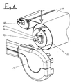
des Fallprofils 18 zu vermeiden. Hierzu ist ein in Fig. 5 gezeigter
Verstellmechanismus zwischen einer Mitnehmerscheibe
28 und der Antriebswelle 24 vorgesehen, wobei die Mitnehmerscheibe
28 drehbar auf einer Kupplungsscheibe 80 sitzt, an
welcher ein Flanschelement 82 drehstarr befestigt ist. An dem
Flanschelement 82 sind Klemmschrauben 84 vorgesehen, die
durch in Umfangsrichtung in der Mitnehmerscheibe 28 vorgesehene
Langlöcher 86 greifen. Auf diese Weise ist in bestimmten
Umfang eine Veränderung der Relativlage der Kupplungsscheibe
80 zu der Mitnehmerscheibe 28 möglich, wobei nach dem Anziehen
der Klemmschrauben 84 eine Übertragung des Antriebsmomentes
über die Klemmflächen möglich ist. Die Übertragung des
Antriebsmoments von der Antriebswelle auf das Flanschelement
82 erfolgt mit Hilfe einer auf der Antriebswelle sitzenden
Vierkantplatte 87 (siehe Fig. 6), die mit Hilfe von Befestigungsschrauben
89 mit dem Flanschelement 82 verschraubbar
ist. Die Kupplungsscheibe 80 weist mittig eine Sechskantöffnung
88 auf, in welcher ein entsprechender Außensechskant
eingefügt werden kann, um eine ggf. vorgesehene weitere Anlage
anzukoppeln. Since the attachment of the toothed belt ends 32, 34 to the
Eine exakte Verstellung der Mitnehmerscheibe 28 mit Bezug auf
die Kupplungsscheibe 80 nach dem Lösen der Klemmschrauben 84
ist mit Hilfe einer Gewindeverstellung 90 möglich. Die Gewindeverstellung
90 besteht im wesentlichen aus einer Stellschraube
92, die axial an einem Kopflager 94 gehalten ist,
das drehbar in einer Bohrung in der Mitnehmerscheibe 28
sitzt. Der Schaft der Stellschraube 92 ist im wesentlichen in
Drehumfangsrichtung ausgerichtet und greift mit seinem Kopf
an einem Widerlager 96 an dem Flanschelement 82 an. In der
Druckrichtung erfolgt ein Verstellen durch die axiale Zustellung
der in einem Hohlgewinde im Kopflager 94 sitzenden
Stellschraube 92, während in der Gegenrichtung die Verstellung
durch den Federmechanismus 26 erfolgt, der zwischen der
Antriebswelle 24 und der Wickelwelle 22 sitzend über das Markisentuch
20, das Fallprofil 18, den Wagen 16 und den Zahnriemen
30 auf die Mitnehmerscheibe 28 wirkt. Die Selbsthemmung
der Stellschraube 92 verhindert dabei ein Verstellen unter
der Wirkung der Federkraft.An exact adjustment of the
Der in Fig. 5 gezeigte Verstellmechanismus ist in seiner Anwendung nicht auf das zuvor beschriebene Beispiel einer Wintergartenmarkise beschränkt, sondern kann grundsätzlich auch bei anderen Anwendungsfällen eingesetzt werden, wo eine genaue Drehwinkelausrichtung einer Zahnscheibe oder dergleichen mit Bezug auf ihre Lagerwelle notwendig ist.The adjustment mechanism shown in Fig. 5 is in its application not to the example of a conservatory awning described above limited, but can in principle also be used in other applications where an exact Angle of rotation alignment of a toothed disc or the like with respect to their bearing shaft is necessary.
In Fig. 7 ist eine Ansicht eines Gegenzugsystems ähnlich Fig.
3 dargestellt, wobei in diesem Fall eine Einstellvorrichtung
100 im Bereich des Gleiters 16 vorgesehen ist, um alternativ
oder in Ergänzung zu der in Fig. 5 gezeigten Einstellvorrichtung
eine Feineinstellung des Zahnriemens 30 vornehmen zu
können, um beispielsweise das Fallprofil 18 auf eine exakt
ausgerichtete Position einstellen zu können und ggf. auch die
Vorspannung des Zahnriemens 30 einstellen zu können. Die Einstellvorrichtung
100 besteht im wesentlichen aus einem Halteteil
102 und einem Klemmstück 104, die mit Hilfe von Klemmschrauben
106 in einer bestimmten axialen Stellung zueinander
verklemmbar sind. Das Halteteil 102 oder das Klemmstück 104
sind mit dem Gleiter 16 fest verbunden und die beiden Enden
des Zahnriemens 30 sind einerseits ortsfest am Gleiter 16 und
andererseits an dem nicht mit dem Gleiter 16 verbundenen und
nach Lösen der Klemmschrauben 106 axial beweglichen Teil,
d. h. dem Halteteil 102 oder dem Klemmstück 104 verbunden.
Die Festlegung der Zahnriemenenden kann beispielsweise auf
eine zuvor beschriebene Art und Weise erfolgen.7 is a view of a counter-pull system similar to FIG.
3, in which case an
Die Verstellbarkeit des Halteteils 102 und des Klemmstückes
104 zueinander wird mit Hilfe von Langlöchern 108 in dem Halteteil
102 ermöglicht, durch welche die Schäfte der Klemmschrauben
106 ragen. Nach dem Lösen der Klemmschrauben 106
können das Halteteil 102 und das Klemmstück 104 stufenlos zueinander
bewegt werden, so daß die gewünschte Einstellung des
Zahnriemens vorgenommen werden kann. Die Länge der Langlöcher
108 entspricht vorzugsweise wenigstens dem Zahnabstand des
Zahnriemens 30, noch besser dem doppelten Zahnabstand, um genügend
Verstellmöglichkeit zu bieten.The adjustability of the holding
Eine weitere Ausführungsform einer Einstellvorrichtung zur
stufenlosen Einstellung des Zahnriemens 30 ist in Fig. 8 gezeigt,
wobei das Gegenzugsystem im übrigen der in Fig. 7 und
auch der in Fig. 3 gezeigten Ausführungsform im wesentlichen
entspricht. Die Einstellvorrichtung 200 besitzt wiederum ein
fest mit dem Gleiter 16 verbundenes Halteteil 202 sowie ein
axial bezüglich des Gleiters und des Halteteils 202 bewegliches
Stellglied 204. Während das erste Ende des Zahnriemens
direkt am Gleiter 16 festgelegt ist, ist das zweite Ende des
Zahnriemens 30 fest mit dem Stellglied 204 verbunden, so daß
wiederum durch eine axiale Relativbewegung der beiden Teile
zueinander die Feineinstellung des Zahnriemens vorgenommen
werden kann. Die Festlegung der Zahnriemenenden als solche an
den entsprechenden Teilen kann in der zuvor beschriebenen Art
und Weise erfolgen.Another embodiment of an adjusting device for
stepless adjustment of the
Bei der Stelleinrichtung 200 liegt das Stellglied 204 zwischen
zwei Vorsprüngen 205, die an dem Halteteil 202 angeformt
sind. Zwei Stellschrauben 206, 207 erstrecken sich
axial durch Gewindebohrungen in diesen Vorsprüngen 205 und
wirken mit ihren Schaftenden unmittelbar auf Stirnflanken des
Stellgliedes 204.In the
Nach einer vorläufigen Montage der Zahnriemenenden in der zuvor
beschriebenen Art und Weise kann nunmehr bei gelöster erster
Stellschraube 206 durch Verdrehen der zweiten Stellschraube
207 die Relativstellung des Stellgliedes 204 zum
Halteteil 202 geändert werden, bis die gewünschte Einstellung
erreicht ist. Durch anschließendes Wiederanziehen der ersten
Stellschraube 206 wird die Einstellposition gesichert.After a preliminary assembly of the toothed belt ends in the previous
described way can now with solved first
Set
Wie bereits erwähnt, können die Einstellvorrichtungen 100
oder 200 mit einer Einstellvorrichtung im Bereich der Riemenscheiben
kombiniert werden, wenn erweiterte Einstellmöglichkeiten
gefordert werden. Grundsätzlich genügt jedoch das Vorsehen
einer Einstellvorrichtung im Bereich der Riemenscheiben
oder des Gleiters auf einer Seite der Gegenzuganlage, um die
gewünschten Einstellmöglichkeiten vornehmen zu können. Beidseitige
Einstellvorrichtungen können dann zweckmäßig sein,
wenn auch die Vorspannung des Zahnriemens 30 auf beiden Seiten
mit Hilfe der Einstellvorrichtungen vorgenommen werden
soll.As already mentioned, the
Claims (10)
Priority Applications (1)
| Application Number | Priority Date | Filing Date | Title |
|---|---|---|---|
| DE20220967U DE20220967U1 (en) | 2001-09-26 | 2002-09-26 | Return motion system for adjusting the hanging device of a winter garden awning arranged between a shaft and a profile has lateral ends each fixed to a carriage or glider, and pulling elements fixed to lateral guides |
Applications Claiming Priority (2)
| Application Number | Priority Date | Filing Date | Title |
|---|---|---|---|
| DE2001147522 DE10147522A1 (en) | 2001-09-26 | 2001-09-26 | Counter pull system for conservatory awnings |
| DE10147522 | 2001-09-26 |
Publications (2)
| Publication Number | Publication Date |
|---|---|
| EP1298264A2 true EP1298264A2 (en) | 2003-04-02 |
| EP1298264A3 EP1298264A3 (en) | 2003-12-10 |
Family
ID=7700394
Family Applications (1)
| Application Number | Title | Priority Date | Filing Date |
|---|---|---|---|
| EP02021496A Withdrawn EP1298264A3 (en) | 2001-09-26 | 2002-09-26 | Back-pull drive for a conservatory awning |
Country Status (2)
| Country | Link |
|---|---|
| EP (1) | EP1298264A3 (en) |
| DE (1) | DE10147522A1 (en) |
Cited By (4)
| Publication number | Priority date | Publication date | Assignee | Title |
|---|---|---|---|---|
| WO2005090704A2 (en) | 2004-03-17 | 2005-09-29 | Dynaco International S.A. | Roller curtain device |
| EP2333193A2 (en) | 2009-12-09 | 2011-06-15 | Renson Sunprotection-Screens NV | Canopy structure |
| ITPD20090401A1 (en) * | 2009-12-30 | 2011-06-30 | Iata Srl | SUPPORT AND HANDLING STRUCTURE FOR A PACKAGE TENT |
| EP3985202A1 (en) * | 2020-10-15 | 2022-04-20 | markilux GmbH + Co. KG | Awning, in particular a winter garden or a weather guard awning with a drive device |
Families Citing this family (2)
| Publication number | Priority date | Publication date | Assignee | Title |
|---|---|---|---|---|
| DE10342661B3 (en) * | 2003-09-16 | 2004-08-05 | Warema Renkhoff Gmbh | Sun blind with deployment of blind material web via sliders at sides of end profile cooperating with counter-tension drive |
| DE102015106528A1 (en) * | 2015-04-28 | 2016-11-03 | Lisa Dräxlmaier GmbH | Vehicle window shade with cable pull concept and drive of the cable pull via toothed belt |
Citations (3)
| Publication number | Priority date | Publication date | Assignee | Title |
|---|---|---|---|---|
| US5035091A (en) | 1988-12-30 | 1991-07-30 | Kabushiki Kaisha Daimon | Automatically operated opening and closing roof |
| DE19914543A1 (en) | 1999-03-31 | 2000-10-05 | Warema Renkhoff Gmbh & Co Kg | Sunshade has winder shaft for sun-blind, drop rod, back-pull drive, compensating system, power transmission, intermediate shaft and driven shafts |
| DE19963862A1 (en) | 1999-12-30 | 2001-07-26 | Mhz Sonnenschutztech Gmbh | Shading device |
Family Cites Families (3)
| Publication number | Priority date | Publication date | Assignee | Title |
|---|---|---|---|---|
| DE8422951U1 (en) * | 1984-08-02 | 1984-10-31 | Walter Paul KG, 7252 Weil der Stadt | LOUVRE |
| DE8530051U1 (en) * | 1985-10-23 | 1985-12-05 | Kästli & Co AG, Bern | All-weather gates |
| DE29718396U1 (en) * | 1997-10-16 | 1999-02-18 | Hoermann Kg Antriebstechnik | Gate drive device |
-
2001
- 2001-09-26 DE DE2001147522 patent/DE10147522A1/en not_active Withdrawn
-
2002
- 2002-09-26 EP EP02021496A patent/EP1298264A3/en not_active Withdrawn
Patent Citations (3)
| Publication number | Priority date | Publication date | Assignee | Title |
|---|---|---|---|---|
| US5035091A (en) | 1988-12-30 | 1991-07-30 | Kabushiki Kaisha Daimon | Automatically operated opening and closing roof |
| DE19914543A1 (en) | 1999-03-31 | 2000-10-05 | Warema Renkhoff Gmbh & Co Kg | Sunshade has winder shaft for sun-blind, drop rod, back-pull drive, compensating system, power transmission, intermediate shaft and driven shafts |
| DE19963862A1 (en) | 1999-12-30 | 2001-07-26 | Mhz Sonnenschutztech Gmbh | Shading device |
Cited By (8)
| Publication number | Priority date | Publication date | Assignee | Title |
|---|---|---|---|---|
| WO2005090704A2 (en) | 2004-03-17 | 2005-09-29 | Dynaco International S.A. | Roller curtain device |
| BE1016320A3 (en) * | 2004-03-17 | 2006-08-01 | Dynaco International Sa | CURTAIN DEVICE unwound. |
| EP2333193A2 (en) | 2009-12-09 | 2011-06-15 | Renson Sunprotection-Screens NV | Canopy structure |
| BE1019071A5 (en) * | 2009-12-09 | 2012-02-07 | Kestelyn Nv | SCREEN CONSTRUCTION WITH A SCREEN CABINET. |
| EP2333193A3 (en) * | 2009-12-09 | 2015-01-28 | Renson Sunprotection-Screens NV | Canopy structure |
| ITPD20090401A1 (en) * | 2009-12-30 | 2011-06-30 | Iata Srl | SUPPORT AND HANDLING STRUCTURE FOR A PACKAGE TENT |
| EP3985202A1 (en) * | 2020-10-15 | 2022-04-20 | markilux GmbH + Co. KG | Awning, in particular a winter garden or a weather guard awning with a drive device |
| DE102020213045A1 (en) | 2020-10-15 | 2022-04-21 | Markilux GmbH + Co. KG | Awning, in particular a conservatory or weather protection awning, with a drive device |
Also Published As
| Publication number | Publication date |
|---|---|
| EP1298264A3 (en) | 2003-12-10 |
| DE10147522A1 (en) | 2003-04-17 |
Similar Documents
| Publication | Publication Date | Title |
|---|---|---|
| DE102007013446B4 (en) | Electric actuator | |
| CH631515A5 (en) | DRIVE FOR A SLAT SHUTTER. | |
| DE19611074A1 (en) | Device and method for adjusting a frameless window pane moved by a double-strand cable window lifter by a tilting movement transverse to the longitudinal axis of the motor vehicle | |
| DE102007041360B4 (en) | Retrofit kit for a sliding door and sliding door system | |
| WO2006128428A2 (en) | Support with a backrest adjuster device for a motor vehicle seat | |
| CH682249A5 (en) | ||
| EP1300270A1 (en) | Lamellar blind and corresponding lamella | |
| DE10014946B4 (en) | Device for adjusting the position of a guide rail for an adjustable window pane of a motor vehicle | |
| DE3843917A1 (en) | Drive device for a rolling surface | |
| EP1641993B1 (en) | Deflection device for a motor vehicle window lift | |
| EP1298264A2 (en) | Back-pull drive for a conservatory awning | |
| EP0864026B1 (en) | Bowden tube window winder with compensation for cable length | |
| DE102009011120A1 (en) | Adjustment device for the window pane of a window regulator | |
| DE4034614C2 (en) | ||
| EP1331339A2 (en) | Hinge for doors, windows and the like | |
| DE20220967U1 (en) | Return motion system for adjusting the hanging device of a winter garden awning arranged between a shaft and a profile has lateral ends each fixed to a carriage or glider, and pulling elements fixed to lateral guides | |
| EP1840312A2 (en) | Sliding door | |
| DE10236869A1 (en) | Gathered blind has winding rollers for draw cords and turning rollers for adjusting incline and with inclined flanks above coupling band guide which diverts ends of coupling bands into desired plane | |
| EP1071859B1 (en) | Closing device for casement windows and leaved doors | |
| DE4123686C2 (en) | Drive for opening and closing curtains, in particular roller blinds, blinds, folding curtains or the like. | |
| EP3473458A1 (en) | Horizontal tensioner for tensioningsystem of tarpaulin | |
| EP1225292A2 (en) | Door | |
| DE102019132564B4 (en) | Positioning device and sun or privacy protection device with such a positioning device | |
| EP0950789B1 (en) | Door drive | |
| EP1126110B1 (en) | Locking device for doors and windows |
Legal Events
| Date | Code | Title | Description |
|---|---|---|---|
| PUAI | Public reference made under article 153(3) epc to a published international application that has entered the european phase |
Free format text: ORIGINAL CODE: 0009012 |
|
| AK | Designated contracting states |
Kind code of ref document: A2 Designated state(s): AT BE BG CH CY CZ DE DK EE ES FI FR GB GR IE IT LI LU MC NL PT SE SK TR Designated state(s): AT BE BG CH CY CZ DE DK EE ES FI FR GB GR IE IT LI LU MC NL PT SE SK TR |
|
| AX | Request for extension of the european patent |
Extension state: AL LT LV MK RO SI |
|
| PUAL | Search report despatched |
Free format text: ORIGINAL CODE: 0009013 |
|
| AK | Designated contracting states |
Kind code of ref document: A3 Designated state(s): AT BE BG CH CY CZ DE DK EE ES FI FR GB GR IE IT LI LU MC NL PT SE SK TR |
|
| AX | Request for extension of the european patent |
Extension state: AL LT LV MK RO SI |
|
| AKX | Designation fees paid | ||
| REG | Reference to a national code |
Ref country code: DE Ref legal event code: 8566 |
|
| STAA | Information on the status of an ep patent application or granted ep patent |
Free format text: STATUS: THE APPLICATION IS DEEMED TO BE WITHDRAWN |
|
| 18D | Application deemed to be withdrawn |
Effective date: 20040611 |