EP1297907A1 - Deckel für Gargerät mit Reinigungsvorrichtung sowie Reinigungsverfahren - Google Patents
Deckel für Gargerät mit Reinigungsvorrichtung sowie Reinigungsverfahren Download PDFInfo
- Publication number
- EP1297907A1 EP1297907A1 EP02015291A EP02015291A EP1297907A1 EP 1297907 A1 EP1297907 A1 EP 1297907A1 EP 02015291 A EP02015291 A EP 02015291A EP 02015291 A EP02015291 A EP 02015291A EP 1297907 A1 EP1297907 A1 EP 1297907A1
- Authority
- EP
- European Patent Office
- Prior art keywords
- fluid
- cooking container
- channel
- lid
- cleaning
- Prior art date
- Legal status (The legal status is an assumption and is not a legal conclusion. Google has not performed a legal analysis and makes no representation as to the accuracy of the status listed.)
- Granted
Links
- 238000010411 cooking Methods 0.000 title claims abstract description 145
- 238000004140 cleaning Methods 0.000 title claims abstract description 61
- 238000000034 method Methods 0.000 title claims abstract description 26
- 239000012530 fluid Substances 0.000 claims description 73
- 239000007788 liquid Substances 0.000 claims description 59
- 238000010791 quenching Methods 0.000 claims description 26
- 230000000171 quenching effect Effects 0.000 claims description 26
- XLYOFNOQVPJJNP-UHFFFAOYSA-N water Chemical compound O XLYOFNOQVPJJNP-UHFFFAOYSA-N 0.000 claims description 24
- 239000007921 spray Substances 0.000 claims description 12
- 230000001105 regulatory effect Effects 0.000 claims description 11
- 238000010438 heat treatment Methods 0.000 claims description 10
- 238000001035 drying Methods 0.000 claims description 8
- 239000003795 chemical substances by application Substances 0.000 claims description 7
- 238000011109 contamination Methods 0.000 claims description 6
- 238000007599 discharging Methods 0.000 claims description 6
- 239000002245 particle Substances 0.000 claims description 5
- 238000007789 sealing Methods 0.000 claims description 5
- 230000001276 controlling effect Effects 0.000 claims description 4
- 239000013505 freshwater Substances 0.000 claims description 3
- 239000003599 detergent Substances 0.000 description 3
- 238000000746 purification Methods 0.000 description 3
- 150000001875 compounds Chemical class 0.000 description 2
- 238000010586 diagram Methods 0.000 description 2
- 230000000694 effects Effects 0.000 description 2
- 238000001914 filtration Methods 0.000 description 2
- 239000007789 gas Substances 0.000 description 2
- 239000012535 impurity Substances 0.000 description 2
- 239000000203 mixture Substances 0.000 description 2
- 239000012459 cleaning agent Substances 0.000 description 1
- 238000004891 communication Methods 0.000 description 1
- 238000009833 condensation Methods 0.000 description 1
- 230000005494 condensation Effects 0.000 description 1
- -1 decalcifier Substances 0.000 description 1
- 238000001514 detection method Methods 0.000 description 1
- 238000011010 flushing procedure Methods 0.000 description 1
- 230000005283 ground state Effects 0.000 description 1
- 230000010354 integration Effects 0.000 description 1
- 238000002791 soaking Methods 0.000 description 1
- 238000009736 wetting Methods 0.000 description 1
Images


Classifications
-
- B—PERFORMING OPERATIONS; TRANSPORTING
- B08—CLEANING
- B08B—CLEANING IN GENERAL; PREVENTION OF FOULING IN GENERAL
- B08B9/00—Cleaning hollow articles by methods or apparatus specially adapted thereto
- B08B9/08—Cleaning containers, e.g. tanks
- B08B9/0804—Cleaning containers having tubular shape, e.g. casks, barrels, drums
- B08B9/0813—Cleaning containers having tubular shape, e.g. casks, barrels, drums by the force of jets or sprays
-
- A—HUMAN NECESSITIES
- A47—FURNITURE; DOMESTIC ARTICLES OR APPLIANCES; COFFEE MILLS; SPICE MILLS; SUCTION CLEANERS IN GENERAL
- A47J—KITCHEN EQUIPMENT; COFFEE MILLS; SPICE MILLS; APPARATUS FOR MAKING BEVERAGES
- A47J27/00—Cooking-vessels
- A47J27/14—Cooking-vessels for use in hotels, restaurants, or canteens
-
- B—PERFORMING OPERATIONS; TRANSPORTING
- B08—CLEANING
- B08B—CLEANING IN GENERAL; PREVENTION OF FOULING IN GENERAL
- B08B9/00—Cleaning hollow articles by methods or apparatus specially adapted thereto
- B08B9/08—Cleaning containers, e.g. tanks
-
- F—MECHANICAL ENGINEERING; LIGHTING; HEATING; WEAPONS; BLASTING
- F24—HEATING; RANGES; VENTILATING
- F24C—DOMESTIC STOVES OR RANGES ; DETAILS OF DOMESTIC STOVES OR RANGES, OF GENERAL APPLICATION
- F24C14/00—Stoves or ranges having self-cleaning provisions, e.g. continuous catalytic cleaning or electrostatic cleaning
- F24C14/005—Stoves or ranges having self-cleaning provisions, e.g. continuous catalytic cleaning or electrostatic cleaning using a cleaning liquid
Definitions
- the invention relates to a lid for a cooking appliance with one of the lid at least partially closable cooking container, in particular in the form of a crucible, wherein in the Cover at least one inlet channel for supplying at least a first fluid in the Cooking container and / or at least a first drainage channel for discharging at least one second fluid from the cooking container at least partially.
- At least one Have cooking container the open at the top and during a cooking process free accessible or closable with a lid, wherein the lid at least one Inlet and has a flow channel for a fluid.
- US Pat. No. 3,598,105 discloses a generic lid for a cooking container known which has a plurality of channels through which the cooking container during a Garreaes additional liquid can be supplied without the lid of the Cooking tray must be removed.
- the channels serve for the discharge of Water vapor and non-condensable gases.
- the Leave cleaning liquid in the cooking container In the open cooking container by the user manually a cleaning liquid filled, and for soaking the impurities present in the cooking container is the Leave cleaning liquid in the cooking container and possibly heat it up. To Lapse of a certain period of time existing in the cooking container Contaminated by brushes mechanically dissolved and together with the Cleaning fluid drained from the cooking container by tilting the cooking container. Finally, the cooking container is manually dried by the user. This Cleaning process is very time consuming for the user, and there are large amounts of Cleaning fluid necessary.
- a cleaning device for a Cooking appliance with at least one cooking container described, in particular a swivel arm having spray nozzles and a brush head, via a control and / or regulating unit is operable to clean the cooking vessel.
- This swivel arm can at least partially be introduced in the cooking containers, so that the spray nozzles on the cooking container Liquid is supplied for cleaning while a mechanical cleaning over the Brush head is possible.
- the Cleaning device represents an additional structure on the cooking appliance.
- DE 28 42 771 C2 discloses a device for heat treatment of Food known, which has a cabinet-shaped cooking space. It is intended that located within the cooking chamber on the ground, on walls or in the cooking chamber Air baffle nozzles or a spray arm can be arranged. These serve the Supply of cleaning agents or water.
- Object of the present invention is therefore to provide the generic cover for a Further develop cooking appliance such that overcome the disadvantages of the prior art become. Furthermore, a method for cleaning a cooking appliance to overcome said Disadvantages are delivered.
- the object relating to the lid is achieved by a Cleaning device comprising the inlet channel and / or the first outlet channel.
- the cleaning device at least a second through the Gariscuser passing through drain channel for discharging the second fluid from the Includes cooking tray.
- An embodiment of the invention is characterized by at least one with the Inlet channel and / or the first and / or second outlet channel on the cooking container facing side of the lid, preferably via a snap, turn and / or Plug connection, connectable duct end piece.
- the at least one channel end piece a pipe, preferably curved in the form of a snorkel, at least one spray nozzle and / or one, preferably comprising a plurality of spray nozzles, in particular by the by Kanalabschluß Swiss flowing first fluid driven, rotary or Schwenksprinkler includes.
- a further development of the lid according to the invention is characterized by at least a, preferably controllable and / or controllable, first valve in the inlet channel and / or second valve (18) in the first and / or second drainage channel.
- the invention proposes that the cooking container in the area of the Drain channel connectable Kanalabschluß Swisss has a recess.
- a lid according to the invention is characterized by at least one Pivoting device, at least one sealing device and / or at least one Closing device, preferably for sealing the lid on the Cooking tray.
- a lid according to the invention is characterized by a Tilting device for, preferably automatic, controllable and / or adjustable, tilting the Gar matterers, so that at least the first and / or second drain channel at the lowest point of the Tilted cooking container is arranged or are.
- Another embodiment of the invention is characterized by at least one with the inlet channel in operative connection first pump, in particular High pressure pump, a steam generating unit and / or a hot air generating unit.
- a lid according to the invention is characterized by at least one with the first and / or second drain channel operatively connected, in particular Schmutz constitute, second pump, wherein the inlet channel and the first and / or second Drain passage preferably with the interposition of the pump and / or a first sensor for detecting the degree of soiling and / or temperature of the second fluid, in particular via a third valve, are connectable to each other.
- the lid according to the invention has one with the first and / or second drain channel, preferably with the interposition of the second valve, in Compound extinguishing box, wherein the Ausschöschkasten preferably one with the second pump connectable third drain channel, on.
- the quenching box at least a first Inlet for the second fluid, at least one second sensor for detecting the temperature within the quenching box, at least one third sensor for detecting the fluid level in the extinguishing box, an overflow and / or at least one preferably between the Extinguishing box and the second flow channel and / or in the region of the third flow channel arranged filter device comprises.
- the extinguisher box at least a third Fluid in the form of a liquid, such as fresh water, preferably at least a fourth Valve and / or a fourth fluid in the form of a gas and / or vapor, such as Steam, preferably at least a fifth valve and feeds, preferably controlled and / or regulated, can be supplied, and / or the extinguishing box is at least one tab, comprising a cleaning and / or descaling agent, preferably via a Sliding box, can be fed.
- a third Fluid in the form of a liquid such as fresh water
- a fourth Valve and / or a fourth fluid in the form of a gas and / or vapor, such as Steam preferably at least a fifth valve and feeds, preferably controlled and / or regulated
- the extinguishing box is at least one tab, comprising a cleaning and / or descaling agent, preferably via a Sliding box, can be fed.
- a further development of a lid according to the invention is characterized by at least a first reservoir for the first fluid and / or at least a second reservoir for the second fluid, wherein the first reservoir with the inlet channel and the second reservoir can be connected to the first and / or second flow channel, preferably via a Snap, turn and / or plug connection.
- a lid according to the invention is characterized by one with the first and / or second pump, the first, second, third, fourth and / or fifth valve, the Steam generating unit, the hot air generating unit, the tilting device, the Pivoting device, the sealing device, the closure device, the first, second and / or third sensor, and / or at least a fourth sensor for detecting the Temperature of the lid and / or the cooking vessel, in operative connection control and / or Control unit.
- the invention also proposes that the cover at least partially is transparent.
- the cooking container is or will be supplied.
- the method according to the invention is characterized in that a Cleaner, rinse aid, descaler, rinse and / or water, in vapor form and / or liquid, is selected as the first fluid, wherein the first fluid is preferably supplied under high pressure.
- the invention proposes that the second fluid from the first fluid and Dirt particles is composed, preferably the degree of contamination of the second fluid is used for controlling and / or rules.
- the second fluid from the cooking container through the first and / or second drainage channel preferably by means of a in the extinguishing box, especially by supplying water into the quenching box, generated negative pressure, is sucked and / or the expiration of the second fluid from the cooking container through the first and / or second drainage channel, in particular by tilting the Gar mattersers, due to Gravitational force, supported.
- a method according to the invention is characterized by several Purification phases, wherein during a cleaning phase of the inlet channel and the first and / or second drainage channel are interconnected, and the first and / or second Fluid is repeatedly circulated through the cooking container or be, the duration of the Circulation, preferably as a function of the degree of soiling of the second fluid, is controlled and / or regulated, and discarded the second fluid after opening the circuit becomes.
- the method can provide that, preferably before the cleaning phase, in a Heating phase, the first and / or second fluid in the cooking container, preferably by Heating the cooking container, is heated.
- a further development of the method according to the invention is characterized by at least one drying phase, preferably after the cleaning phase, wherein during heated the drying phase of the cooking container and / or supplied to the cooking container hot air is so that the liquid residues located in the cooking container evaporated and by the first and / or second drain channel are discharged.
- the invention proposes that after selection of a Cleaning program with a certain number and sequence of cleaning, Heating and / or drying phases by the user cleaning automatically, controlled and / or regulated, preferably as a function of the temperature of the first and / or second fluids, the cooking container and / or the lid and / or the Pollution degree of the second fluid is performed.
- the invention is thus based on the finding that a cooking appliance are designed in this way can, that an automatic cleaning of a cooking vessel while minimizing the necessary amount of cleaning fluids without additional structures on the Cooking device is made possible, namely by integration of a cleaning device in the Lid of the cooking appliance.
- Fig. 1 is a cooking appliance 1, the lid 3 according to the invention and a cooking container. 5 comprises, shown.
- a shutter mechanism 7 and the lid 3 is not Seals shown in the contact area between the lid 3 and the cooking container. 5 on.
- the lid 3 is connected via a hinge 9 with respect to the cooking container 5 for opening the Gar mattersers 5 pivotally mounted.
- an inlet channel 11 which with a first line 13 is connectable and comprises a first valve 14, and a drain channel 15, which is connected to a second line 17 and comprises a second valve 18, integrated.
- a Kanalabschluß in the form of a rotary sprinkler 19 connectable by means of a suitable self-locking connector device 20.
- This rotary sprayer 19 has a variable height A and includes a plurality of spray nozzles 21.
- the drainage channel 15 is provided with a Kanalabschluß Swiss in the form of a snorkel 23rd connectable by means of a suitable self-locking connector device 24.
- This Snorkel 23 has a length B, that of the height of the cooking container 5 in the region of the outlet the drain channel 15 from the lid 3 corresponds to. Thus, the snorkel 23 is on the Bottom of the cooking vessel 5 on.
- the height A of the rotary sprinkler 19 of the Depth of the cooking vessel 5 adapted to a uniform wetting of the cooking vessel 5 with a fluid emerging from the spray nozzles 21 and thus a maximum possible To achieve cleaning effect of the cooking vessel 5.
- the in the cooking container 5 on the Rotary sprayer 19 introduced fluid, z.
- As detergent, detergent, decalcifier, water and / or water vapor, collects at the bottom of the cooking vessel 5 in the form of the liquid 25.
- This liquid 25 is through the connected to the drainage channel 15 snorkel 23rd dissipated.
- the length B of the snorkel 23 of the depth of the Gar mattersers 5 adapted, and the cooking container 5 has a recess in the end region of the snorkel 23.
- FIG. 2 shows a further embodiment of a cooking device 1 according to the invention.
- the reference numerals correspond to those in FIG. 1.
- a cooking container 5 ' which has a greater depth than the cooking container 5 shown in FIG has, is used.
- the height A of the rotary sprinkler 19 is this greater depth customized. It can thus be commercially available cooking containers, the different depths have, use with the cover 3 of the invention and clean.
- the cooking container 5 ' with the lid 3 via the shutter mechanism 7 and the Hinge 9 is connected via a tilting device 27 relative to that shown in Fig. 1 Basic position of the cooking vessel 5 tilted by 90 °.
- the tilting device 27 is not at one shown housing of the cooking device 1 attached.
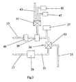
- FIG. 3 the course of the lines 13 and 17 of the lid 3 of the invention Figures 1 and 2 and their connection with other elements of the cooking device 1 shown.
- the second line 17 leads to a dirty pump 29, by means of which the liquid 25 can be sucked out of the cooking container 5, 5 '. In addition, it comes in the pump 29 for crushing present in the liquid 25 dirt particles.
- the pump 29 is connected to a valve 33.
- the valve 33 has three Outputs on. An output is connected to a disposal line 35 through which the Liquid 25 can be removed from the cooking appliance 1.
- the second output of the valve 33 is connected to an exhaust air line 36, while the third output to the first line 13 is connected.
- To the first line 13 is a hot air generating unit 37 via a not connected valve connected.
- a Evaporator 39 located in the first line 13 a Evaporator 39.
- the evaporator 39 is in turn with a valve 41, which in turn with a water inlet 43, a rinse tank 45 and a cleaner tank 47 connected is connected.
- a cleaning process according to the invention proceeds as follows:
- a user first connects the rotary sprinkler 19 with the inlet channel 11 and optionally, the drainage channel 15 with the snorkel 23. Then he selects by means of a not shown input unit from a cleaning program, which then automatically expires.
- the sequence of the cleaning program is via a control unit, not shown, which with the closure mechanism 7, the tilting device 27, the valves 14, 18, 33, 41, the pumps 29, 49, the hot air generating unit 37, the evaporator 39 and not represented sensors is in communication, regulated.
- An exemplary cleaning program includes the following program items:
- valves 14, 41 are controlled so that a mixture of water and Cleaner liquid from the water inlet 43 and the cleaner tank 47 through the switched off evaporator 39, the switched-off high-pressure pump 49, the first line 13, the inlet channel 11 and the rotary sprinkler 19 the cooking container 5, 5 'is supplied.
- the Valve 18 is initially closed, so that in the cooking container 5, 5 ', the liquid 25th accumulates. Reaches the liquid level 25 inside the cooking vessel 5, 5 'a determined value, which is detected by a sensor, not shown, the valve 33rd controlled so that a connection between the lines 31 and 13 is formed. About that In addition, the connection between the pipe 13 and the hot air generating unit 37 becomes closed. After opening the valve 18, the pump 29 and the high pressure pump 49th switched on.
- the liquid 25 is either via the snorkel 23rd or aspirated directly through the drain channel 15 from the cooking container 5, 5 '.
- the pump 29 Be any liquid particles 25 crushed in the liquid, and the Liquid 25 flows via the line 31 and the valve 33 into the first line 13.
- the High pressure pump 49 the liquid 25 under high pressure via the first line 13 and fed to the inlet channel 11 to the rotary sprinkler 19, it comes to a circulation the cleaning fleet.
- the liquid 25 is circulated in the cooking container 5, 5 ', and by means of the cleaning liquor flow, a mechanical cleaning of the cooking vessel 5, 5 ' reached. If the contamination of the cleaning liquor exceeds a certain value, which is detected by a sensor, not shown, the high-pressure pump 49th switched off, and the valve 33 is switched so that the cleaning liquor via the pump 29th is sucked from the cooking container 5, 5 'and the disposal line 35 is supplied.
- valve 33 is again in the Starting position posed.
- the circulation of the Liquid 25 repeated, the liquid 25 to increase the cleaning effect is first evaporated by means of the evaporator 39.
- the evaporator 39 and the high-pressure pump 49 are turned off and in the cooking container 5, 5 'existing liquid 25 via the pump 29 and the Disposal line 35 discharged.
- a mixture of water and rinse aid which by controlling the valve 41 from the water inlet 43 and the rinse aid container 45 be mixed in an analogous manner in the purification steps described above circulated through the cooking container 5, 5 '.
- This cleaning step is finally followed by a drying step.
- a drying step In this will be via the hot air generating unit 37 to the cooking container 5, 5 'via the first line 13 Hot air supplied, in addition, the walls of the cooking vessel 5, 5 'by not shown Heating devices can be heated.
- the hot air passes through the drainage channel 15, the opened valve 18, the lines 17 and 31 and the valve 33 through the exhaust air line 36th from the cooking appliance 1.
- FIG. 4 shows a cooking appliance 50 with a further lid 51 according to the invention.
- the cover 51 has only one inlet channel 53, which can be connected to a rotary sprinkler 55 is.
- the cooking appliance 50 also includes a cooking container in the form of a crucible 59th Der Crucible 59 is tiltably mounted on a tilting device 61.
- the tilting device 61 extends at least partially a drain channel 63 from the crucible 59, by means of which in the crucible 59 existing fluid drain or can be sucked.
- the drainage channel 63 is by means of a valve 65 closed.
- the valve 65 is connected on the side facing away from the drainage channel 63 with a manifold 67.
- the distributor 67 has a first opening 69, by means of which the drainage channel 63 can be connected to an extinguishing box 71.
- the distributor 67 has a second opening 72, which allows a connection of the distributor 67 via a line 75 with a disposal channel 77.
- the two openings 69 and 72 can optionally be opened or closed via a slide 74 driven by a drive device 73.
- a filter device 79 which is connected to the first opening 69 is connected, arranged. This serves to drain in a via the drainage channel 63 Fluid to filter out foreign objects out, so that they are not in the Ablöschkasten 71 can reach.
- the quenching channel 71 has two drainage channels in addition to the first opening 69 81, 82 and an overflow 83.
- a Filter device 85 is arranged, which prevents that in a quenching box 71st existing liquid 87 existing dirt particles reach a pump 89 can.
- the extinguishing box 71 also includes two inlets 93, 95.
- the liquid 87 can on the one hand through the drainage channel 63 from the crucible 59 in the Abschöschkasten 71 arrive, on the other hand, the Ablöschkasten 71 via the second Feed 95 to be supplied to a liquid.
- For controlling the steam supply or the liquid supply via the Inlets 93, 95 are disposed within the Abschökktens 71 sensors 105, 107. These allow the detection of the level of the fluid 87 and the temperature within the Quenching box 71.
- the sensors 105 and 107 are connected to a not shown control or Control unit, further with the valves 65, 91, 97, 99, 101, 103 and the drive 73 in Active compound is connected.
- the Ablöschkasten 71 via the second inlet 95th supplied cold water, it comes to a condensation of within the Flushing box 71 existing gaseous fluid.
- This negative pressure within the Flush box 71 causes, in the case in which the slider 74 in the in Fig. 4 is shown and the valve 65 is opened, via the drain passage 63 in the Crucible 59 existing fluid is sucked out of the crucible 59. This can happen on the one hand to act liquids that are within a cleaning process within of the crucible 59 is located.
- the control unit In order to determine the time at which the water in the crucible 59 has the desired temperature, the control unit, not shown, with a lid 51 arranged, also not shown, temperature sensor for measuring the temperature of the lid 51 in conjunction.
- the valve 65 When the liquid within the crucible 59 reaches the desired temperature, the valve 65 is opened and the second opening 72 is closed by means of the slide 74. As a result, the liquid present inside the crucible 59 flows into the quenching box 71.
- the liquid 87 collecting within the quenching box 71 is sucked out of the quenching box 71 by means of the pump 89 through the first discharge channel 81. Subsequently, the liquid 87 is supplied via an open valve 111 to the inlet channel 53 of the lid 51.
- the liquid is circulated in the crucible 59 and thus a cleaning of the crucible 59 is achieved.
- the valve 111 is closed on the one hand and a valve 109 is opened on the other hand. This causes the liquid 87 driven by the pump 89 to be supplied to the discharge channel 77.
- the pump 89 is first turned off and water is supplied to the quenching box 71 via the valves 101 and 103.
- valve 109 is closed and the valve 111 is opened again.
- the valves 101 and 103 are opened or closed by means of the control unit, not shown, in such a way that the temperature measured via the sensor 105 reaches a desired desired value equivalent.
- the liquid 87 through the crucible 59 is recirculated, the liquid 87 is once completely replaced for circulation.
- the slider 74 is moved by means of the drive means 73 so that the first Opening 69 is closed, the pump 89 is turned off and the valve 111 closed and the valve 91 is opened.
- the liquid 87 present in the quenching box 71 is discharged via the discharge passage 82 and the valve 91 is also supplied to the discharge channel 77.
- the valve 91 is closed and via the valves 101 and 103 the extinguishing box 71 liquid for rinsing the crucible 59th fed.
- the valve 111 is opened and the pump 89 is turned on, so that the Liquid is in turn circulated through the crucible 59.
- the pump 89 is turned off and the liquid 87 in the quenching box 71 collected and stored there for a later cleaning process.
- the crucible 59 dried in a subsequent drying phase by the walls of the Tiegel 59 are heated by heating elements, not shown. This happens at closed valve 65.
- the valve 65 opened and within the Abschökktens 71 creates a negative pressure, passing through the valves 101 and 103 water introduced into the Ablöschkasten 71 and so in the crucible 59 existing Steam is effectively extracted.
- the valve 65 is the Crucible 59 is opened by the user by opening the lid 51 and finally the Rotary sprayer 55 taken.
- a lid for a cooking appliance and a method for Cleaning a cooking appliance provided to minimize the necessary amount Cleaning fluids and avoiding additional structures on the cooking appliance to carry out automatic cleaning of a cooking container arranged in the cooking appliance.
Landscapes
- Engineering & Computer Science (AREA)
- Mechanical Engineering (AREA)
- Chemical & Material Sciences (AREA)
- Chemical Kinetics & Catalysis (AREA)
- Combustion & Propulsion (AREA)
- General Engineering & Computer Science (AREA)
- Food Science & Technology (AREA)
- Cookers (AREA)
Abstract
Description
- Fig. 1
- eine Schnittansicht durch ein Gargerät mit einem erfindungsgemäßen Deckel, im Grundzustand des Garbehälters;
- Fig. 2
- eine Schnittansicht eines weiteren Gargeräts mit dem erfindungsgemäßen Deckel von Fig. 1, im gekippten Zustand des Garbehälters;
- Fig. 3
- ein Blockdiagramm für die Zuleitungen des Deckels der Figuren 1 und 2; und
- Fig. 4
- ein Blockdiagramm für die Zuleitungen eines Deckels gemäß einer weiteren Ausführungsform der Erfindung
Das Ventil 65 ist auf der dem Ablaufkanal 63 abgewandten Seite mit einem Verteiler 67 verbunden. Der Verteiler 67 weist eine erste Öffnung 69 auf, mittels der der Ablaufkanal 63 mit einem Ablöschkasten 71 verbindbar ist. Ferner weist der Verteiler 67 eine zweite Öffnung 72 auf, die eine Verbindung des Verteilers 67 über eine Leitung 75 mit einem Entsorgungskanal 77 ermöglicht. Die beiden Öffnungen 69 und 72 können wahlweise über einen mittels einer Antriebseinrichtung 73 angetriebenen Schieber 74 geöffnet bzw. verschlossen werden. Wird somit das Ventil 65 geöffnet und der Schieber 74 derart positioniert, daß die zweite Öffnung 72 geöffnet ist, während die erste Öffnung 69 verschlossen ist, so fließt ein innerhalb des Tiegels 59 vorhandenes Fluid über den Ablaufkanal 63 durch den Verteiler 67 und die Leitung 75 in den Entsorgungskanal 77.
Zunächst wird von einem Benutzer bei geöffnetem Deckel 51 sowie geschlossenem Ventil 65 manuell Wasser in den Tiegel 59 eingeführt. Ferner wird dem in den Tiegel 59 eingefüllten Wasser ein Reinigungs-und/oder Entkalkungsmittel in Form eines Tabs hinzugefügt. Anschließend wird vom Benutzer an den Zulaufkanal 53 der Drehsprinkler 55 angeschlossen und der Tiegel 59 mittels des Deckels 51 verschlossen. Anschließend wird über nicht dargestellte Heizelemente am Tiegel 59 das Wasser innerhalb des Tiegels 59 erwärmt. Um den Zeitpunkt zu bestimmen, an dem das Wasser im Tiegel 59 die gewünschte Temperatur hat, steht die nicht dargestellte Steuer- und Regeleinheit mit einem im Deckel 51 angeordneten, ebenfalls nicht dargestellten Temperatursensor zur Messung der Temperatur des Deckels 51 in Verbindung. Erreicht die Flüssigkeit innerhalb des Tiegels 59 die gewünschte Temperatur, so wird das Ventil 65 geöffnet und die zweite Öffnung 72 mittels des Schiebers 74 verschlossen. Dadurch fließt die innerhalb des Tiegels 59 vorhandene Flüssigkeit in den Ablöschkasten 71. Die sich innerhalb des Ablöschkastens 71 sammelnde Flüssigkeit 87 wird mittels der Pumpe 89 durch den ersten Ablaufkanal 81 aus dem Ablöschkasten 71 abgesaugt. Anschließend wird die Flüssigkeit 87 über ein geöffnetes Ventil 111 dem Zulaufkanal 53 des Deckels 51 zugeführt. Dadurch wird die Flüssigkeit in dem Tiegel 59 umgewälzt und somit eine Reinigung des Tiegels 59 erreicht. Erreicht der Verschmutzungsgrad der Flüssigkeit 87 einen bestimmten Wert, der mittels eines nicht dargestellten Sensors erfaßt wird, so wird einerseits das Ventil 111 geschlossen und andererseits ein Ventil 109 geöffnet. Dies bewirkt, daß die durch die Pumpe 89 angetriebene Flüssigkeit 87 dem Entsorgungskanal 77 zugeführt wird. Erreicht der Pegel der Flüssigkeit 87 innerhalb des Ablöschkastens 71 einen über den Sensor 107 erfaßten Minimalpegel, so wird die Pumpe 89 zunächst abgeschaltet und über die Ventile 101 und 103 dem Ablöschkasten 71 Wasser zugeführt. Dieses durch den Zulaufkanal 95 zugeführte Frischwasser wird anschließend durch die Pumpe 89 dem Tiegel 59 über den Zulaufkanal 53 zugeführt, indem das Ventil 109 geschlossen und das Ventil 111 wiederum geöffnet wird. Um zu vermeiden, daß die durch den Tiegel 59 umgewälzte Flüssigkeit erneut erwärmt werden muß, werden die Ventile 101 und 103 mittels der nicht dargestellten Steuer- und Regeleinheit derartig geöffnet bzw. geschlossen, daß die über den Sensor 105 gemessene Temperatur einen gewünschten Soll-Wert entspricht.
- 1
- Gargerät
- 3
- Deckel
- 5, 5'
- Garbehälter
- 7
- Verschlußmechanismus
- 9
- Scharnier
- 11
- Zulaufkanal
- 13
- Leitung
- 14
- Ventil
- 15
- Ablaufkanal
- 17
- Leitung
- 18
- Ventil
- 19
- Drehsprinkler
- 20
- Steckverbindungsvorrichtung
- 21
- Sprühdüse
- 23
- Schnorchel
- 24
- Steckverbindungsvorrichtung
- 25
- Flüssigkeit
- 27
- Kippvorrichtung
- 29
- Pumpe
- 31
- Leitung
- 33
- Ventil
- 35
- Entsorgungsleitung
- 36
- Abluftleitung
- 37
- Heißlufterzeugungseinheit
- 39
- Verdampfer
- 41
- Ventil
- 43
- Wasserzulauf
- 45
- Klarspülerbehälter
- 47
- Reinigerbehälter
- 49
- Hochdruckpumpe
- 50
- Gargerät
- 51
- Deckel
- 53
- Zulaufkanal
- 55
- Drehsprinkler
- 59
- Tiegel
- 61
- Kippvorrichtung
- 63
- Ablaufkanal
- 65
- Ventil
- 67
- Verteiler
- 69
- Öffnung
- 71
- Ablöschkasten
- 72
- Öffnung
- 73
- Antriebseinrichtung
- 74
- Schieber
- 75
- Leitung
- 77
- Entsorgungskanal
- 79
- Filtereinrichtung
- 81
- Ablaufkanal
- 82
- Ablaufkanal
- 83
- Überlauf
- 85
- Filtereinrichtung
- 87
- Flüssigkeit
- 89
- Pumpe
- 91
- Ventil
- 93
- Zulauf
- 95
- Zulauf
- 97
- Ventil
- 99
- Ventil
- 101
- Ventil
- 103
- Ventil
- 105
- Sensor
- 107
- Sensor
- 109
- Ventil
- 111
- Ventil
- A
- Bauhöhe
- B
- Länge
Claims (25)
- Deckel für ein Gargerät (1, 50) mit einem von dem Deckel (3, 51) zumindest teilweise verschließbaren Garbehälter (5, 5', 59), insbesondere in Form eines Tiegels, wobei in dem Deckel (3, 51) mindestens ein Zulaufkanal (11, 53) zum Zuführen zumindest eines ersten Fluids in den Garbehälter (5, 5', 59) und/oder mindestens ein erster Ablaufkanal (15) zum Abführen zumindest eines zweiten Fluids aus dem Garbehälter (5, 5', 59) zumindest teilweise verlaufen, gekennzeichnet durch
eine Reinigungsvorrichtung, die den Zulaufkanal (11, 53) und/oder den ersten Ablaufkanal (15) umfaßt. - Deckel nach Anspruch 1, dadurch gekennzeichnet, daß
die Reinigungsvorrichtung zumindest einen zweiten durch den Garbehälter (59) hindurchtretenden Ablaufkanal (63) zum Abführen des zweiten Fluids aus dem Garbehälter (59) umfaßt. - Deckel nach Anspruch 1 oder 2, gekennzeichnet durch
zumindest ein mit dem Zulaufkanal (11, 53) und/oder dem ersten und/oder zweiten Ablaufkanal (15) auf der dem Garbehälter (5, 5') zugewandten Seite des Deckels (3), vorzugsweise über eine Schnapp-, Dreh- und/oder Steckverbindung (20, 24), verbindbares Kanalabschlußstück (19, 23, 55). - Deckel nach Anspruch 3, dadurch gekennzeichnet, daß
das zumindest eine Kanalabschlußstück ein Rohr, vorzugsweise in Form eines Schnorchels (23) gekrümmt, zumindest eine Sprühdüse und/oder einen, vorzugsweise mehrere Sprühdüsen (21) umfassenden, insbesondere durch das durch das Kanalabschlußstück fließende erste Fluid angetriebenen, Dreh- oder Schwenksprinkler (19, 55) umfaßt. - Deckel nach einem der vorangehenden Ansprüche, gekennzeichnet durch
zumindest ein, vorzugsweise steuer- und/oder regelbares, erstes Ventil (14) in dem Zulaufkanal (11) und/oder zweites Ventil (18, 65) in dem ersten und/oder zweiten Ablaufkanal (15, 63). - Deckel nach einem der vorangehenden Ansprüche, dadurch gekennzeichnet, daß
der Garbehälter (5, 5') im Bereich des mit dem Ablaufkanal (15) verbindbaren Kanalabschlußstücks (23) eine Vertiefung aufweist. - Deckel nach einem der vorangehenden Ansprüche, gekennzeichnet durch
zumindest eine Verschwenkvorrichtung (9), zumindest eine Dichtungsvorrichtung und/oder zumindest eine Verschlußvorrichtung (7), vorzugsweise zum dichten Verschließen des Deckels (3) auf dem Garbehälter (5, 5'). - Deckel nach einem der vorangehenden Ansprüche, gekennzeichnet durch
eine Kippvorrichtung (27, 61) zum, vorzugsweise automatischen, steuer- und/oder regelbaren, Kippen des Garbehälters (5, 5', 59), so daß zumindest der erste und/oder zweite Ablaufkanal (15, 63) am tiefsten Punkt des gekippten Garbehälters (5, 5', 59) angeordnet ist bzw. sind. - Deckel nach einem der vorangehenden Ansprüche, gekennzeichnet durch
zumindest eine mit dem Zulaufkanal (11) in Wirkverbindung stehende erste Pumpe, insbesondere Hochdruckpumpe (49), eine Dampferzeugungseinheit (39) und/oder eine Heißlufterzeugungseinheit (37). - Deckel nach einem der vorangehenden Ansprüche, gekennzeichnet durch
zumindest eine mit dem ersten und/oder zweiten Ablaufkanal (15, 63) in Wirkverbindung stehende, insbesondere schmutzgängige, zweite Pumpe (29, 89), wobei der Zulaufkanal (11, 53) und der erste und/oder zweite Ablaufkanal (15, 63) vorzugsweise unter Zwischenschaltung der Pumpe (29, 89) und/oder eines ersten Sensors zum Erfassen des Verschmutzungsgrads und/oder Temperatur des zweiten Fluids, insbesondere über ein drittes Ventil (33, 111), miteinander verbindbar sind. - Deckel nach einem der vorangehenden Ansprüche, gekennzeichnet durch
einen mit des zweiten und/oder zweiten Ablaufkanal (63), vorzugsweise unter Zwischenschaltung des zweiten Ventils (65), in Verbindung stehenden Ablöschkasten (71), wobei der Ablöschkasten (71) vorzugsweise einen mit der zweiten Pumpe (89) verbindbaren dritten Ablaufkanal (81) aufweist. - Deckel nach Anspruch 11, dadurch gekennzeichnet, daß
der Ablöschkasten (71) zumindest einen ersten Zulauf (69) für das zweite Fluid, zumindest einen zweiten Sensor (105) zur Erfassung der Temperatur innerhalb des Ablöschkastens (71), zumindest einen dritten Sensor (107) zur Erfassung des Fluidpegels im Ablöschkasten (71), einen Überlauf (83) und/oder zumindest eine vorzugsweise zwischen dem Ablöschkasten (71) und dem zweiten Ablaufkanal (63) und/oder im Bereich des dritten Ablaufkanals (81) angeordnete Filtereinrichtung (79, 85) umfaßt. - Deckel nach Anspruch 11 oder 12, dadurch gekennzeichnet, daß
dem Ablöschkasten (71) zumindest ein drittes Fluid in Form einer Flüssigkeit, wie Frischwasser, über vorzugsweise zumindest ein viertes Ventil (101, 103) und/oder ein viertes Fluid in Form eines Gases und/oder Dampfes, wie Wasserdampfes, über vorzugsweise zumindest ein fünftes Ventil (97, 99) und Zuläufe (93, 95), vorzugsweise gesteuert und/oder geregelt, zuführbar ist, und/oder dem Ablöschkasten (71) ist zumindest ein Tab, umfassend ein Reinigungs- und/oder Entkalkungsmittel, vorzugsweise über einen Schiebekasten, zuführbar. - Deckel nach einem der vorangehenden Ansprüche, gekennzeichnet durch
zumindest ein erstes Reservoir für das erste Fluid und/oder zumindest ein zweites Reservoir für das zweite Fluid, wobei das erste Reservoir mit dem Zulaufkanal (11) und das zweite Reservoir mit dem ersten und/oder zweiten Ablaufkanal (15) verbindbar sind, vorzugsweise über eine Schnapp-, Dreh- und/oder Steckverbindung. - Deckel nach einem der vorangehenden Ansprüche, gekennzeichnet durch
eine mit der ersten und/oder zweiten Pumpe (29, 49, 89), dem ersten, zweiten, dritten, vierten und/oder fünften Ventil (14, 18, 33, 65, 97, 99, 101, 103, 111), der Dampferzeugungseinheit (39), der Heißlufterzeugungseinheit (37), der Kippvorrichtung (27, 61), der Verschwenkvorrichtung (9), der Dichtvorrichtung, der Verschlußvorrichtung (7), dem ersten, zweiten und/oder dritten Sensor (105, 107) und/oder zumindest einem vierten Sensor zur Erfassung der Temperatur des Deckels und/oder des Garbehälters in Wirkverbindung stehende Steuer- und/oder Regeleinheit. - Deckel nach einem der vorangehenden Ansprüche, dadurch gekennzeichnet, daß der Deckel (3) zumindest bereichsweise transparent ist.
- Verfahren zum Reinigen eines Gargeräts mit einem Deckel nach einem der vorangehenden Ansprüche, umfassend folgende Schritte:a) insbesondere dichtes, Verschließen des Garbehälters mittels des Deckels; undb) Zuführen des ersten Fluids durch den Zulaufkanal in den Garbehälter und/oder Abführen des zweiten Fluids durch den Ablaufkanal aus dem Garbehälter.
- Verfahren nach Anspruch 17, dadurch gekennzeichnet, daß,
insbesondere vor dem Verschließen des Garbehälters, das erste Fluid und/oder ein Reinigungs- und/oder Entkalkungsmittel, vorzugsweise in Tab-Form, dem Garbehälter zugeführt wird bzw. werden. - Verfahren nach Anspruch 17 oder 18, dadurch gekennzeichnet, daß
ein Reiniger, ein Klarspüler, ein Entkalker, ein Spülmittel und/oder Wasser, in Dampfform und/oder flüssig, als erstes Fluid ausgewählt wird bzw. werden, wobei das erste Fluid vorzugsweise unter Hochdruck zugeführt wird. - Verfahren nach einem der Ansprüche 17 bis 19, dadurch gekennzeichnet, daß
das zweite Fluid aus dem ersten Fluid und Schmutzpartikeln zusammengesetzt wird, wobei vorzugsweise der Verschmutzungsgrad des zweiten Fluids zum Steuern und/oder Regeln herangezogen wird. - Verfahren nach einem der Ansprüche 17 bis 20, dadurch gekennzeichnet, daß
das zweite Fluid aus dem Garbehälter durch den ersten und/oder zweiten Ablaufkanal, vorzugsweise mittels eines in dem Ablöschkasten, insbesondere durch Zufuhr von Wasser in den Ablöschkasten, erzeugten Unterdrucks, abgesaugt wird, und/oder der Ablauf des zweiten Fluids aus dem Garbehälter durch den ersten und/oder zweiten Ablaufkanal, insbesondere durch Kippen des Garbehälters, aufgrund der Gravitationskraft, unterstützt wird. - Verfahren nach einem der Ansprüche 17 bis 21, gekennzeichnet durch
mehrere Reinigungsphasen, wobei während einer Reinigungsphase der Zulaufkanal und der erste und/oder zweite Ablaufkanal miteinander verbunden werden, und das erste und/oder zweite Fluid mehrfach durch den Garbehälter umgewälzt wird bzw. werden, wobei die Dauer der Umwälzung, vorzugsweise in Abhängigkeit vom Verschmutzungsgrad des zweiten Fluids, gesteuert und/oder geregelt wird, und das zweite Fluid nach Öffnen des Kreislaufes entsorgt wird. - Verfahren nach Anspruch 22, dadurch gekennzeichnet, daß,
vorzugsweise vor der Reinigungsphase, in einer Erwärmungsphase das erste und/oder zweite Fluid im Garbehälter, vorzugsweise durch Erwärmen des Garbehälters, erwärmt wird. - Verfahren nach Anspruch 21 oder 22, gekennzeichnet durch
zumindest eine Trocknungsphase, vorzugsweise nach der Reinigunsphase, wobei während der Trocknungsphase der Garbehälter erwärmt und/oder dem Garbehälter Heißluft zugeführt wird, so daß die im Garbehälter befindlichen Flüssigkeitsreste verdampft und durch den ersten und/oder zweiten Ablaufkanal abgeführt werden. - Verfahren nach einem der Ansprüche 17 bis 24, dadurch gekennzeichnet, daß
nach Auswahl eines Reinigungsprogrammes mit einer bestimmten Anzahl und Reihenfolge von Reinigungs-, Erwärmungs- und/oder Trocknungsphasen durch den Benutzer die Reinigung automatisch, gesteuert und/oder geregelt, vorzugsweise in Abhängigkeit von der Temperatur des ersten und/oder zweiten Fluids, des Garbehälters und/oder des Deckels und/oder des Verschmutzungsgrades des zweiten Fluids durchgeführt wird.
Applications Claiming Priority (2)
| Application Number | Priority Date | Filing Date | Title |
|---|---|---|---|
| DE10134005 | 2001-07-12 | ||
| DE10134005A DE10134005C2 (de) | 2001-07-12 | 2001-07-12 | Deckel für Gargerät mit Reinigungsvorrichtung sowie Reinigungsverfahren |
Publications (2)
| Publication Number | Publication Date |
|---|---|
| EP1297907A1 true EP1297907A1 (de) | 2003-04-02 |
| EP1297907B1 EP1297907B1 (de) | 2006-02-22 |
Family
ID=7691610
Family Applications (1)
| Application Number | Title | Priority Date | Filing Date |
|---|---|---|---|
| EP02015291A Expired - Lifetime EP1297907B1 (de) | 2001-07-12 | 2002-07-09 | Deckel für Gargerät mit Reinigungsvorrichtung sowie Reinigungsverfahren |
Country Status (2)
| Country | Link |
|---|---|
| EP (1) | EP1297907B1 (de) |
| DE (2) | DE10134005C2 (de) |
Cited By (8)
| Publication number | Priority date | Publication date | Assignee | Title |
|---|---|---|---|---|
| ITVR20100029A1 (it) * | 2010-02-17 | 2011-08-18 | A & Jp S R L | Dispositivo di cottura e mobile da cucina dotato di tale dispositivo. |
| DE202013004549U1 (de) | 2013-05-15 | 2013-08-01 | Labetherm Limited Zweigniederlassung Deutschland | Reinigungssystem vom Tiegel eines Gargeräts |
| DE102013008272A1 (de) | 2013-05-15 | 2014-12-04 | Labetherm Ltd. | Reinigungssystem und Reinigungsvervahren vom Tiegel eines Gargeräts |
| CN109106237A (zh) * | 2017-07-31 | 2019-01-01 | 九阳股份有限公司 | 一种喷淋清洗食品加工机 |
| CN110227405A (zh) * | 2019-06-21 | 2019-09-13 | 包宇峰 | 一种具有清洁功能的使用便捷的反应釜 |
| CN114308813A (zh) * | 2021-12-21 | 2022-04-12 | 贵溪红石金属有限公司 | 一种铜带清洗烘干设备 |
| EP2747606B2 (de) † | 2011-10-18 | 2023-03-15 | MKN Maschinenfabrik Kurt Neubauer GmbH & Co. KG | Verfahren zur reinigung eines tiegels sowie gargerät mit einem tiegel und einer reinigungseinrichtung |
| CN118788693A (zh) * | 2023-04-14 | 2024-10-18 | 佛山市顺德区美的电热电器制造有限公司 | 风管自清洁控制方法、装置、烹饪设备及存储介质 |
Families Citing this family (16)
| Publication number | Priority date | Publication date | Assignee | Title |
|---|---|---|---|---|
| DE102006010460B4 (de) * | 2006-03-03 | 2016-02-25 | Rational Ag | Verfahren zur Reinigung eines Gargeräts |
| DE102007005502A1 (de) * | 2007-01-30 | 2008-07-31 | Rational Ag | Verfahren zur Reinigung eines Gargeräts und Gargerät hierfür |
| EP2273199A3 (de) * | 2009-07-09 | 2011-10-12 | BSH Bosch und Siemens Hausgeräte GmbH | Hausgerätvorrichtung |
| EP2273200A1 (de) * | 2009-07-10 | 2011-01-12 | Rational AG | Gargerät mit Mehrfachwasseranschluss und automatischer Wasserwahl in Abhängigkeit eines Gar- oder Reinigungsprogramms |
| DE102011105716A1 (de) * | 2011-06-23 | 2012-12-27 | MKN Maschinenfabrik Kurt Neubauer GmbH & Co. KG | Gargerät mit einem Tiegel und Verfahren zur Reinigung des Tiegels |
| DE102011120907A1 (de) | 2011-12-12 | 2013-06-13 | Frima-T Sas | Verfahren zum Reinigen eines Gargeräts und Gargerät |
| DE102012004197B4 (de) | 2012-03-01 | 2022-12-08 | Rational Ag | Gargerät mit Reinigungsfunktion |
| FI124015B (fi) | 2012-08-07 | 2014-01-31 | Dieta Oy | Suurtalouskattilan pesujärjestelmä |
| DE202012104257U1 (de) | 2012-11-06 | 2012-12-06 | Frima International Ag | Gargerät mit einer Reinigungseinrichtung |
| DE102014102572A1 (de) | 2014-02-27 | 2015-08-27 | Rational Aktiengesellschaft | Reinigungsverfahren für ein Gargerät und Gargerät zur Durchführung des Verfahrens |
| DE102016119552A1 (de) * | 2016-10-13 | 2018-04-19 | Frima International Ag | Gargerät mit einem tiegelförmigen Garbehälter |
| DE102017117224A1 (de) * | 2017-07-31 | 2019-01-31 | Miele & Cie. Kg | Gargerät und Verfahren |
| DE102019124860B4 (de) | 2019-09-16 | 2024-01-25 | MKN Maschinenfabrik Kurt Neubauer GmbH & Co. KG | Verfahren zum Entkalken einer Hochdruckreinigungseinrichtung eines Druckgargeräts sowie dazu eingerichtetes Druckgargerät |
| DE102022123069B3 (de) | 2022-09-09 | 2023-10-05 | MKN Maschinenfabrik Kurt Neubauer GmbH & Co. KG | Gewerbliches Gargerät und Verfahren zum Betreiben eines solchen Gargeräts |
| DE102022123067B3 (de) * | 2022-09-09 | 2023-10-05 | MKN Maschinenfabrik Kurt Neubauer GmbH & Co. KG | Gewerbliches Gargerät |
| DE102022123068B3 (de) * | 2022-09-09 | 2023-10-05 | MKN Maschinenfabrik Kurt Neubauer GmbH & Co. KG | Gewerbliches Gargerät |
Citations (3)
| Publication number | Priority date | Publication date | Assignee | Title |
|---|---|---|---|---|
| US3598105A (en) * | 1970-02-25 | 1971-08-10 | Liborio B Cristaldi | Cover for cooking, heating or frying vessels with fluid transport and venting means |
| DE2842771A1 (de) * | 1978-09-30 | 1980-04-10 | Lechmetall Landsberg Gmbh | Vorrichtung und verfahren zur waermebehandlung von nahrungsmitteln, insbesondere zur zubereitung von speisen |
| DE10124703C1 (de) * | 2001-05-18 | 2002-10-31 | Frima Sa | Gargerät mit Reinigungsvorrichtung |
Family Cites Families (2)
| Publication number | Priority date | Publication date | Assignee | Title |
|---|---|---|---|---|
| DE19653279A1 (de) * | 1996-12-20 | 1998-06-25 | Kueppersbusch | Gargerät für Lebensmittel |
| DE19961835C2 (de) * | 1999-12-21 | 2003-03-20 | Rational Ag | Verfahren sowie Vorrichtung zum automatischen Gargerätereinigen |
-
2001
- 2001-07-12 DE DE10134005A patent/DE10134005C2/de not_active Expired - Fee Related
-
2002
- 2002-07-09 DE DE50205855T patent/DE50205855D1/de not_active Expired - Lifetime
- 2002-07-09 EP EP02015291A patent/EP1297907B1/de not_active Expired - Lifetime
Patent Citations (3)
| Publication number | Priority date | Publication date | Assignee | Title |
|---|---|---|---|---|
| US3598105A (en) * | 1970-02-25 | 1971-08-10 | Liborio B Cristaldi | Cover for cooking, heating or frying vessels with fluid transport and venting means |
| DE2842771A1 (de) * | 1978-09-30 | 1980-04-10 | Lechmetall Landsberg Gmbh | Vorrichtung und verfahren zur waermebehandlung von nahrungsmitteln, insbesondere zur zubereitung von speisen |
| DE10124703C1 (de) * | 2001-05-18 | 2002-10-31 | Frima Sa | Gargerät mit Reinigungsvorrichtung |
Cited By (8)
| Publication number | Priority date | Publication date | Assignee | Title |
|---|---|---|---|---|
| ITVR20100029A1 (it) * | 2010-02-17 | 2011-08-18 | A & Jp S R L | Dispositivo di cottura e mobile da cucina dotato di tale dispositivo. |
| EP2747606B2 (de) † | 2011-10-18 | 2023-03-15 | MKN Maschinenfabrik Kurt Neubauer GmbH & Co. KG | Verfahren zur reinigung eines tiegels sowie gargerät mit einem tiegel und einer reinigungseinrichtung |
| DE202013004549U1 (de) | 2013-05-15 | 2013-08-01 | Labetherm Limited Zweigniederlassung Deutschland | Reinigungssystem vom Tiegel eines Gargeräts |
| DE102013008272A1 (de) | 2013-05-15 | 2014-12-04 | Labetherm Ltd. | Reinigungssystem und Reinigungsvervahren vom Tiegel eines Gargeräts |
| CN109106237A (zh) * | 2017-07-31 | 2019-01-01 | 九阳股份有限公司 | 一种喷淋清洗食品加工机 |
| CN110227405A (zh) * | 2019-06-21 | 2019-09-13 | 包宇峰 | 一种具有清洁功能的使用便捷的反应釜 |
| CN114308813A (zh) * | 2021-12-21 | 2022-04-12 | 贵溪红石金属有限公司 | 一种铜带清洗烘干设备 |
| CN118788693A (zh) * | 2023-04-14 | 2024-10-18 | 佛山市顺德区美的电热电器制造有限公司 | 风管自清洁控制方法、装置、烹饪设备及存储介质 |
Also Published As
| Publication number | Publication date |
|---|---|
| DE10134005A1 (de) | 2003-01-30 |
| EP1297907B1 (de) | 2006-02-22 |
| DE10134005C2 (de) | 2003-08-21 |
| DE50205855D1 (de) | 2006-04-27 |
Similar Documents
| Publication | Publication Date | Title |
|---|---|---|
| EP1297907B1 (de) | Deckel für Gargerät mit Reinigungsvorrichtung sowie Reinigungsverfahren | |
| EP1275334B1 (de) | Multifunktionaler Deckel für ein Gargerät | |
| EP1364166B1 (de) | Vorrichtung und verfahren zur reinigung eines gargerätes | |
| EP0383327B1 (de) | Dampferzeuger für Gargeräte mit Entkalkungseinrichtung | |
| EP4281708B1 (de) | Gargerät für die grossküche mit fettabsaugeinrichtung, sowie verfahren zum betreiben eines solchen gargeräts mit fettabsaugung | |
| DE2756428C2 (de) | ||
| DE19961835C2 (de) | Verfahren sowie Vorrichtung zum automatischen Gargerätereinigen | |
| DE4108911C2 (de) | Feineiserzeuger | |
| EP3759397B1 (de) | Tischlüfter und verfahren zum reinigen eines tischlüfters | |
| EP0892220A1 (de) | Ofen zur Wärmebehandlung von Lebensmitteln und Verfahren zum Reinigen des Innenraums | |
| DE3722282C2 (de) | ||
| DE69429541T2 (de) | Teilewascher | |
| DE4324507A1 (de) | Backofen | |
| EP1108384B1 (de) | Haushaltgerät zum drucklosen Dampfgaren | |
| WO2009129902A1 (de) | Gerät und verfahren zum desinfizieren, sterilisieren und/oder pflegen von ärtzlichen, insbesondere zahnärtzlichen instrumenten | |
| EP0801271A1 (de) | Ofen und Verfahren zur Reinigung eines Ofenraums | |
| DE102020117842A1 (de) | Reinigungschemiebaugruppe und Gargerät | |
| DE4427460C2 (de) | Backofen zum Dampfgaren | |
| DE3700567A1 (de) | Kondensoreinrichtung fuer in einem backofen entstehende wrasen | |
| DE29606655U1 (de) | Ofen zur Wärmebehandlung von Lebensmitteln | |
| EP2605661B1 (de) | Dampfgargerätvorrichtung | |
| WO2016059129A2 (de) | Verfahren und vorrichtung für die backofenreinigung | |
| DE10033479A1 (de) | Wasserspareinrichtung mit Pumpe für Sanitärduschen | |
| EP3076086B1 (de) | Haushaltsgargerät und verfahren zum betreiben eines haushaltsgargeräts | |
| DE19749649C2 (de) | Trockenvorrichtung und Trocknungsverfahren |
Legal Events
| Date | Code | Title | Description |
|---|---|---|---|
| PUAI | Public reference made under article 153(3) epc to a published international application that has entered the european phase |
Free format text: ORIGINAL CODE: 0009012 |
|
| AK | Designated contracting states |
Kind code of ref document: A1 Designated state(s): AT BE BG CH CY CZ DE DK EE ES FI FR GB GR IE IT LI LU MC NL PT SE SK TR |
|
| AX | Request for extension of the european patent |
Extension state: AL LT LV MK RO SI |
|
| 17P | Request for examination filed |
Effective date: 20030822 |
|
| AKX | Designation fees paid |
Designated state(s): DE FR GB IT |
|
| GRAP | Despatch of communication of intention to grant a patent |
Free format text: ORIGINAL CODE: EPIDOSNIGR1 |
|
| GRAS | Grant fee paid |
Free format text: ORIGINAL CODE: EPIDOSNIGR3 |
|
| GRAA | (expected) grant |
Free format text: ORIGINAL CODE: 0009210 |
|
| AK | Designated contracting states |
Kind code of ref document: B1 Designated state(s): DE FR GB IT |
|
| REG | Reference to a national code |
Ref country code: GB Ref legal event code: FG4D Free format text: NOT ENGLISH |
|
| REF | Corresponds to: |
Ref document number: 50205855 Country of ref document: DE Date of ref document: 20060427 Kind code of ref document: P |
|
| GBT | Gb: translation of ep patent filed (gb section 77(6)(a)/1977) |
Effective date: 20060522 |
|
| ET | Fr: translation filed | ||
| PLBE | No opposition filed within time limit |
Free format text: ORIGINAL CODE: 0009261 |
|
| STAA | Information on the status of an ep patent application or granted ep patent |
Free format text: STATUS: NO OPPOSITION FILED WITHIN TIME LIMIT |
|
| 26N | No opposition filed |
Effective date: 20061123 |
|
| PGFP | Annual fee paid to national office [announced via postgrant information from national office to epo] |
Ref country code: GB Payment date: 20080709 Year of fee payment: 7 |
|
| GBPC | Gb: european patent ceased through non-payment of renewal fee |
Effective date: 20090709 |
|
| PG25 | Lapsed in a contracting state [announced via postgrant information from national office to epo] |
Ref country code: GB Free format text: LAPSE BECAUSE OF NON-PAYMENT OF DUE FEES Effective date: 20090709 |
|
| REG | Reference to a national code |
Ref country code: FR Ref legal event code: PLFP Year of fee payment: 15 |
|
| REG | Reference to a national code |
Ref country code: FR Ref legal event code: PLFP Year of fee payment: 16 |
|
| REG | Reference to a national code |
Ref country code: FR Ref legal event code: PLFP Year of fee payment: 17 |
|
| PGFP | Annual fee paid to national office [announced via postgrant information from national office to epo] |
Ref country code: IT Payment date: 20180720 Year of fee payment: 17 Ref country code: FR Payment date: 20180723 Year of fee payment: 17 |
|
| REG | Reference to a national code |
Ref country code: DE Ref legal event code: R084 Ref document number: 50205855 Country of ref document: DE |
|
| PG25 | Lapsed in a contracting state [announced via postgrant information from national office to epo] |
Ref country code: FR Free format text: LAPSE BECAUSE OF NON-PAYMENT OF DUE FEES Effective date: 20190731 |
|
| PG25 | Lapsed in a contracting state [announced via postgrant information from national office to epo] |
Ref country code: IT Free format text: LAPSE BECAUSE OF NON-PAYMENT OF DUE FEES Effective date: 20190709 |
|
| PGFP | Annual fee paid to national office [announced via postgrant information from national office to epo] |
Ref country code: DE Payment date: 20210721 Year of fee payment: 20 |
|
| REG | Reference to a national code |
Ref country code: DE Ref legal event code: R071 Ref document number: 50205855 Country of ref document: DE |