EP1295521A1 - Arbeitsgerät und Gerät zur Rasen-,Garten- und Grundstückspflege - Google Patents
Arbeitsgerät und Gerät zur Rasen-,Garten- und Grundstückspflege Download PDFInfo
- Publication number
- EP1295521A1 EP1295521A1 EP02021074A EP02021074A EP1295521A1 EP 1295521 A1 EP1295521 A1 EP 1295521A1 EP 02021074 A EP02021074 A EP 02021074A EP 02021074 A EP02021074 A EP 02021074A EP 1295521 A1 EP1295521 A1 EP 1295521A1
- Authority
- EP
- European Patent Office
- Prior art keywords
- control
- control element
- spar
- operator
- speed
- Prior art date
- Legal status (The legal status is an assumption and is not a legal conclusion. Google has not performed a legal analysis and makes no representation as to the accuracy of the status listed.)
- Granted
Links
Images






Classifications
-
- A—HUMAN NECESSITIES
- A01—AGRICULTURE; FORESTRY; ANIMAL HUSBANDRY; HUNTING; TRAPPING; FISHING
- A01D—HARVESTING; MOWING
- A01D34/00—Mowers; Mowing apparatus of harvesters
- A01D34/01—Mowers; Mowing apparatus of harvesters characterised by features relating to the type of cutting apparatus
- A01D34/412—Mowers; Mowing apparatus of harvesters characterised by features relating to the type of cutting apparatus having rotating cutters
- A01D34/63—Mowers; Mowing apparatus of harvesters characterised by features relating to the type of cutting apparatus having rotating cutters having cutters rotating about a vertical axis
- A01D34/67—Mowers; Mowing apparatus of harvesters characterised by features relating to the type of cutting apparatus having rotating cutters having cutters rotating about a vertical axis hand-guided by a walking operator
- A01D34/68—Mowers; Mowing apparatus of harvesters characterised by features relating to the type of cutting apparatus having rotating cutters having cutters rotating about a vertical axis hand-guided by a walking operator with motor driven cutters or wheels
- A01D34/6806—Driving mechanisms
-
- A—HUMAN NECESSITIES
- A01—AGRICULTURE; FORESTRY; ANIMAL HUSBANDRY; HUNTING; TRAPPING; FISHING
- A01D—HARVESTING; MOWING
- A01D34/00—Mowers; Mowing apparatus of harvesters
- A01D34/01—Mowers; Mowing apparatus of harvesters characterised by features relating to the type of cutting apparatus
- A01D34/412—Mowers; Mowing apparatus of harvesters characterised by features relating to the type of cutting apparatus having rotating cutters
- A01D34/63—Mowers; Mowing apparatus of harvesters characterised by features relating to the type of cutting apparatus having rotating cutters having cutters rotating about a vertical axis
- A01D34/67—Mowers; Mowing apparatus of harvesters characterised by features relating to the type of cutting apparatus having rotating cutters having cutters rotating about a vertical axis hand-guided by a walking operator
- A01D34/68—Mowers; Mowing apparatus of harvesters characterised by features relating to the type of cutting apparatus having rotating cutters having cutters rotating about a vertical axis hand-guided by a walking operator with motor driven cutters or wheels
- A01D2034/6843—Control levers on the handle of the mower
-
- A—HUMAN NECESSITIES
- A01—AGRICULTURE; FORESTRY; ANIMAL HUSBANDRY; HUNTING; TRAPPING; FISHING
- A01D—HARVESTING; MOWING
- A01D2101/00—Lawn-mowers
-
- Y—GENERAL TAGGING OF NEW TECHNOLOGICAL DEVELOPMENTS; GENERAL TAGGING OF CROSS-SECTIONAL TECHNOLOGIES SPANNING OVER SEVERAL SECTIONS OF THE IPC; TECHNICAL SUBJECTS COVERED BY FORMER USPC CROSS-REFERENCE ART COLLECTIONS [XRACs] AND DIGESTS
- Y10—TECHNICAL SUBJECTS COVERED BY FORMER USPC
- Y10S—TECHNICAL SUBJECTS COVERED BY FORMER USPC CROSS-REFERENCE ART COLLECTIONS [XRACs] AND DIGESTS
- Y10S56/00—Harvesters
- Y10S56/18—Handles
Definitions
- the invention relates to a self-propelled implement a frame, a motor and at least one drivable Wheel that can be connected to the motor via a gearbox, and a spar, with the spar in a frame opposite end region at least a first and a second Control are provided, as well as a vehicle for lawn, Garden and property maintenance.
- Known tools or devices for lawn, garden and Property maintenance which are hand-guided, can Have speed control devices which actuated by an operator during operation be so that the implement with an individual Speed moves.
- a traction drive moves the implement proportional to the walking speed of the operator.
- US-A-4,558,558 shows a lawn mower with a Vehicle speed control system, which rotates on has a handle attached control handle. The control handle is on the spar along two orthogonal axes of rotation provided pivotable.
- US-A-6,082,083 shows a Vehicle speed control system with a rotatable Engine control bracket, which swivels with a slidable Handle is connected.
- the object on which the invention is based is seen in to overcome this problem.
- a Work equipment can be made available, which on rough Has greater stability and by a Operator can be better controlled.
- a self-propelled work tool Provided using a frame with a spar a preferably substantially U-shaped rear End area has.
- a motor is provided on the frame and with at least one drivable wheel via a gear connected.
- the gearbox is one by one Operator operable control connected, which at least one speed control element or a first one Control element, which is preferably connected to the transmission or is connectable, and has a second control element, which form a presence switch or such can have.
- the first control is in one actual implement or the frame facing away, preferably at least substantially U-shaped rear Swivel area of the spar is provided.
- the second Control element is movable on the first control element, preferably also provided pivotable.
- Each of the controls or both controls can in the form of one-piece or multi-piece temples be carried out because such simple and inexpensive in the Manufacturing and assembly are.
- the execution in Art of divided handles or handle elements is cheap because here there is a possibility that an operator is only on one of the handles has to attack to perform the desired function achieve.
- Such grip elements can, for example, L- or C-shaped or ergonomically designed in another way.
- At least one of the controls can work with the gearbox a connection to be connected effectively, for example influence a driving speed of the implement.
- the transmission can be used, for example, as a traction device or Belt transmission or as another variable transmission be trained.
- the connection can, for example, by at least one push-pull cable are formed. But it is also an electrical, pneumatic or hydraulic one Provide connection.
- control element For unintentional or even unintentionally strong actuation to counteract the control element (s) can on the Controls or between this / these and the spar means be provided to counteract movement.
- This Means can, for example, by springs, pressure cylinders, etc. be formed. This function can be done in a simple way can be achieved by using friction discs.
- the first control can act as a speed control be trained that the driving speed or also a working speed of the implement in Influenced by its swivel position.
- second control can be a Activate presence switch or the second control can have or act as such.
- Controls are commonly called dead man's switches referred to, since it is an active actuation by a Operator require to operate the implement permit. For example, when you release the second Control element may be provided that the implement or Engine deactivated, the transmission disengaged, a tool, how a cutter bar, a brush etc. is deactivated.
- a guide can be provided on one of the control elements, so that with a pivoting movement of the control or the Controls led a connection and thus their function is improved.
- An essentially stationary holding element can be attached to the spar be provided.
- An operator can use such attack the position of a control or both Controls, especially when working on uneven surfaces Stabilize the surface, for example, a more constant driving speed can be maintained can. It also becomes a quick one Counteracted fatigue.
- control elements based on the implement at least essentially after extend above. But it is also a different arrangement possible.
- the implement can be any self-propelled or act hand-held implement. In particular that is Tool but as a device for lawn, garden or Real estate maintenance carried out.
- Such devices are for example lawn mowers, scarifiers, sweepers, Snow removal equipment, garden milling machines, bar mowers etc.
- the control element is mounted on a guide rail or Spar of an implement a controller, which by a Operator or a user can be operated pivotally attached.
- a control has at least a bracket element or a bracket with at least in Mainly U-shaped end area on the spar in opposite side areas is pivotally attached.
- the control system is equipped with a gearbox of the implement a connection, for example in the manner of a push-pull cable connected, but it is also another mechanical or also an electrical or hydraulic / pneumatic connection conceivable.
- the connection works in such a way that when the controller, preferably forward, is pivoted at the connection pulled or operated.
- FIG 1 a perspective view of a Lawnmower or a hand-held implement 10 shown, which has the features of the present invention.
- FIG Shown embodiments shown should be described it will be apparent that the present invention in many different embodiments can be formed.
- the implement 10 essentially has a frame 12, a drive 14 and one by an operator actuatable control 16 on.
- the present invention in any suitable type of hand-held, self-propelled implement can be integrated.
- the frame 12 essentially has a mower 18 and a spar 20. With the mower 18 are Wheels 22 connected.
- the spar 20 extends from the mower 18 up and back.
- the spar 20 is adjustably connected to the mower 18.
- the Spar 20 has two U-shaped handle elements 20a, 20b, which connected together in series to make a stiff To form handle assembly.
- This stiff handle assembly can with the mower 18 stationary or he could with the mower 18 be easily connected.
- Embodiments could be of any suitable type, shape or size Handle assembly to be provided.
- the implement 10 could also have a grass catcher which is attached to the spar 20 and is attached to an ejection opening of the mower 18.
- the drive 14 has a motor 24 and a drive wheel gear or a gear 26.
- the Engine 24 executed in the manner of an internal combustion engine.
- motor 24 could be by any suitable type of motor are formed, for example by an electric motor.
- the Motor 24 includes a drive shaft, which with a Cutting knife or a cutter bar 28 is connected.
- the cutter bar 28 is arranged below the mower 18.
- the transmission 26 is also connected to the motor 24.
- the Transmission 26 is between engine 24 and at least one driven wheel 22d switched. Are in the prior art many different types of gears are known.
- Teen could suitable type of transmission between the motor 24 and the drivable wheel 22d are provided.
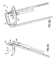
- the controller 16 has an upper, rear end region of the spar 20 connected. It will now also refer to the figures 2A and 2B, in which an upper grip element 20b is shown, which by an operator actuatable control 16 in an unactuated or OFF position will be shown.
- the Controller 16 is essentially a speed control element or a first control element 30, a Deadman circuit or a presence switch or a second control element 32, a first connection 34, a second Connection 36 and a movement resistance device or a Friction disc pack 38.
- the control element 30 is essentially U-shaped Components or a bracket 40 and a guide 42 on.
- the lever or bracket 40 has two legs 44, 46.
- the legs 44, 46 are with opposite side areas 48a, 48b of the handle element 20b pivotally connected.
- the first leg 44 is longer formed as the second leg 46.
- An end portion 47 of the first leg 44 extends over a pivot bearing of the first leg 44 on a side region 48a of the spar 20.
- the bracket 40 thus forms a lever.
- the bracket 40 could be in the form of a handle, one or two "L” one or two "C” or a ring (possibly with spaced end regions).
- the first control 30 in alternative embodiments components of any suitable Have size, shape and type.
- the first control element 30 could also on the spar 20 in a suitable manner be movably attached.
- the movement resistance device in the present Embodiment a friction disc pack 38.
- This Friction disc pack 38 is between the second leg 46 and the side portion 48b of the spar 20.
- the friction disk pack 38 is on a pivot pin 50a placed on the leg 46 with connects the side area 48b.
- the friction disc pack 38 provides increased frictional resistance to movement of the first control element 30 with reference to the spar 20 for Available. This increase in resistance to one Movement of the first control element 30 in relation to the spar 20 has a working machine on the ground 10, like a lawn mower, due to problems as cheap proven which in case of underground irregularities or Uneven floors, such as small holes or bumps on the the implement 10 hits, can occur.
- Friction disc pack 38 can cause the spar 20 to shake if that Tool 10 hits uneven or rough terrain unintentionally moving the first control element 30 cause. Providing the friction disk pack 38 contributes to this at, such an unintentional movement significantly to reduce. This way, unintentional Changes in speed of the implement 10 over the Subsurface to be reduced.
- the Movement resistance device between the first Control 30 and the spar 20 in any suitable manner and Be provided way. In another embodiment, could the movement resistance device may not be provided.
- the opposite leg 44 of the bracket 40 is with a Side area 38a of the spar 20 via a pivot pin 48a pivotally connected.
- the guide 42 on the bracket 40 and the handle member 20b the pivot pin 50b attached.
- the guide 42 is in the Essentially wheel-shaped.
- the outer periphery of the guide 42 faces a circumferential groove.
- any suitable type of leadership could be provided.
- the guide 42 could not be provided.
- On Wire 54b could be wrapped around the guide 42, and the Guide 42 could be provided rotatably.
- connection 34, 36 has an outer one Sheath 52, a soul or an inner wire 54, which of the jacket 52 is surrounded, and fasteners 56.
- the Fasteners 56 are stationary with a front and connected to a rear end portion of the outer shells 52.
- the inner wires 54 can be in the shells 52 and Move fasteners 56 in the longitudinal direction.
- the Fastening means 56 in the rear end region of FIG Connections 34, 36 are stationary with a holder 58 connected.
- the holder 58 in addition, a handle or a holding element 68.
- the Holding element 68 is substantially L-shaped and extends forward.
- any suitable type of holding element and fastening system of the Retaining element can be provided on the spar 20.
- the spar 20 could have no holding element.
- On rear end portion of the inner wire 54a of the first Connection 34 is with the end portion 47 of the U-shaped first Leg 44 connected.
- the front end of the inner Wire 54a is connected to the transmission 26, which is a Traction device disc can have, which to the tension on a traction means or a belt between the motor 24 and the driven wheel 22d to raise or lower to be moved can.
- a rear end portion of the inner wire 54b of the second Connection 36 is connected to the second control element 32 (see FIG. 4A and 4B).
- the rear end of the wire 54b extends from its fastener 56 along the Bottom and the rear side area of the depression or Groove in the guide 42.
- the wire 54b is with a Presence system connected to the engine 24, which can be implemented in the manner of a brake, for example, what braking force can apply to a flywheel of the engine 24.
- the front end portion of the inner wire 54b is one Brake connected to the flywheel or engine 24 to stop.
- the front end portion of the inner wire 54b can connected to an engine shutdown switch or system the cutter bar 28 from the motor 24 separates that it is no longer driven. In different Embodiments could be of any suitable size, shape or type of connections are provided. If the Presence switch 32 is in its OFF position, is the presence system in an OFF position and prevents the implement 10 cutting or working grass.
- the second control element 32 is movable with the first Control 30 connected.
- the second control element 32 as a lever or bracket executed and has a one-piece, substantially U-shaped Element on.
- the second control 32 could be any suitable size or Take shape or could have more than one element.
- the Presence switch 32 has legs 60, 62, which with the U-shaped bracket 40 can be pivoted via pivot pins 64a, 64b are connected. In alternative embodiments, this could second control element 32 movable with the first control element 30 connected in any appropriate way.
- the End portion of wire 54b is connected to leg 60 via Fasteners 66 connected.
- Control element 32 has a central area 70, which in a is arranged upward position. This However, central area 70 is from central area 30a spaced. This is why the second is Control element 32 through an angle A, as seen in FIG. 2A can be offset. The angle A is about 70 °. However, any suitable angle could be provided become.
- the wire 54b is underneath, for example Tension that a spring provided on the motor 24 on it draws. The through the wire 54b to the second control 32nd applied force is sufficient to control the second control 32 in the direction of its unactuated position. Around the second control element 32 from its unactuated position an operator must have sufficient force to overcome the force that is created by the spring-loaded wire 54b is applied. In alternatives Embodiments could be any suitable type of facility used to move the second control 32 towards to burden his unconfirmed position.
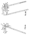
- FIGS. 3A and 3B in which the handle member 20b and by an operator actuatable controller 16 are shown such that the Controller 16 has been moved to an operating or ON position.
- the first Control 30 In this first effective working position, the first Control 30 has not yet been deactivated or neutral position moves.
- the transmission 26 is in a neutral position when the first control 30 is its occupies an unactuated position. In this neutral position no driving force from the motor 24 to the driven one Transfer wheel / driven wheels 22d.
- the first Control 30 can be moved forward on the wire 54a and pull the gear 26 out of its neutral position to bring a driving position.
- FIGS. 4A and 4B in which are operated by an operator 16 is shown in a second working or ON position.
- an operator has both second control element 32 and the first control element 30 after pushed forward to both central areas 30a and 70 and turn it down as shown by arrow B.
- This second position represents one for both elements 30, 32 fully actuated position.
- the two elements 30, 32 both now extend in a substantially straight line forward direction. In alternative embodiments however, the two controls 30, 32 could easily follow be angled up or down.
- the first control element 30 was moved towards the grip element 68. This allows it an operator, the three elements 30, 32 and 68 with with one hand.
- the first control 30 was only in FIG brought his maximum swiveled position if that Tool and the operator with a steep slope would climb at high speed. But anyone could appropriate speed depending on the position of the first control element 30 can be provided.
- the transmission 26 is a Variable speed gearbox.
- the share or the Amount of driving force which is from the motor 24 to the driven wheels is transmitted depends on the position of the Wire 54a.
- the rotational speed of the driven wheels 22d between a neutral and a Maximum speed, depending on the angular position of the first control 30 vary when the first Control 30 over the angle C (see FIG. 3A) from its Neutral position, which is shown in Fig. 3A, in its Maximum speed position pivoted according to Fig. 4A becomes.
- the speed of the implement 10 on the The underground can thus by the angular position of the first Control element 30 can be controlled based on the spar 20.
- the controller 16 can Set the speed of the implement 10 automatically or decrease if the walking speed of the Operator is less than the speed of the Implement 10 on the ground. This can be done without that a conscious effort or a thought by the Operator must be used.
- the controller 16 can control the speed of the implement 10 also automatically increase if the operator has a desires faster speed by the operator only pushes the first control element 30 forward. This pushing forward movement or force causes the upper one End region of the first control element 30 rotates forward. As the first control 30 rotates forward, it increases the speed of the driven wheels 22d.
- Controller 16 increases in accordance with the present invention the speed of the implement 10 if the gap or the angle between the fixed support member 68 and the first control 30 is reduced.
- the Controller 16 the speed of the wheels 22d when the gap between a rear central region 21 of the grip element 20b and the first control element 30 increases.
- the controller 16 accordingly reduces the speed of the implement 10 when the gap or angle between the stationary handle 68 and the first control element 30 is enlarged and if the gap between the back Central region 21 of the grip element 20b and the first Control 30 decreases.
- the present invention overcomes this problem by rear central region 21 of the spar 20 is allowed by the operator's hands to be pressed down to rotate the implement 10 without the Operator controls 16 automatically down suppressed.
- the operator could control 16 lightly release with one hand (to increase the speed of the Reduce implement 10) while using the other Hand the rear central area of the spar 20 or Presses handle 20b down. This increases control the operator over the implement 10 significantly.
- the Driving control is not just a purely digital type of ON / OFF Control. Instead, the driving control is the present Invention designed as a variable control.
- the Speed of the driving control system is dependent from the angular position of the control bracket or the first Control element 30 related to the stationary handle element 20b changed.
- the present invention could also be features of the present invention on non-variable species of ON / OFF driving control systems.
- the Fastening means 66 moves in relation to the holder 58, but the guide 42 provides a routing path for the wire 54b Available.
- the attendance system remains activated between the first and second positions, as in Figures 3A and 4A is shown.
- the wire 54b thus returns its deactivated or OFF position and that Attendance system returns to its OFF position to the Engine 24, for example, by preventing ignition of one Turn off the spark plug and / or a flywheel brake Actuate motor 24, or the transmission between the motor 24th and to separate the cutter bar 28 and / or the driven one Wheel 22 on turning, for example by creating one Brake to prevent.
- the first Control 30 in its fully actuated position is, the implement 10 will not move forward.
- the speed control device of the present Invention works by the operator or the operator User moves on his or her individual path and presses against the movable control element 30, 32. This in turn, the drive engages proportionally to how quickly the operator goes.
- the present invention represents a system with a first control element 30 and a presence switch or a second control element 32 available, which swivel forwards and backwards. This allows one hand of one of the control elements 30, 32 or moves bracket 40 while the other hand on spar 20 attacks to make turning easier.
- the present Invention can also be a stabilizing handle or a Holding element 68 on the right and / or left side use to control the implement 10 and the Control 16 to stabilize on rough ground.
- the ability a hand on the first control 30 and the Using another hand on the spar 20 makes it easier Turn and improve stabilization of speed.
- the operator can support the first Control 30 or on the first control 30 and the Pull spar 20.
- the present invention provides the Operator several ways to on the spar 20 and the controller 16 and thus improves the control or control for a larger proportion of users.
- On Frictional resistance to movement of the first control element 30 was provided to attach the first control 30 to it prevent you from moving too easily.
- the by Operator-operable controller 80 essentially a first control element 82, a presence switch or a second control element 84 and two connections 86, 88.
- the first control element 82 essentially has a U-shaped shape Bracket 90 and two side mounting brackets 92, 94 on.
- the U-shaped Strap 90 essentially has two legs 96, 98 and a central area 100.
- the mounting brackets 92, 94 are fixed on the U-shaped bracket 90 at connection points or transitions between the central area 100 and the legs 96, 98 appropriate.
- the mounting brackets 92, 94 are pivotable with the handle element 20b connected.
- the mounting bracket 92 extends from the U-shaped one Bracket 90 down and back.
- a cable or wire 102 the Connection 96 is at an end portion of the bracket 92 appropriate.
- a friction disc pack 104 is between the Attachment bracket 94 and the handle member 20b provided.
- the second control element 84 is essentially U-shaped Bracket 106 and a fastener 108.
- the U-shaped Strap 106 essentially has a central area 110 and two legs 112, 114.
- the central area is 110 is rotatably connected to the central region 100 via holder 116.
- any suitable system could used to make the two brackets 106, 90 movable to attach to each other.
- the fastener 108 is with a cable or wire of connection 88.
- the wire extends through a guide holder or guide 118 on the fastening means 92.
- the grip element 20b has a stationary holding element 102 on the right and left sides of the Holms 20 on.
- the holding elements 102 extend in the Mainly in a straight forward direction.
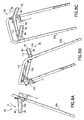
- FIGS. 7A-7C show that by an operator actuatable controller 80 in a completely deactivated Position similar to that shown in Figures 2A - 2B.
- the Leg of the first control element 82 and the second Control 84 essentially up and forward.
- the Legs 96, 98, 112, 114 also extend inwards towards each other.
- FIGS. 7A-7C taken, in which the controller 80 in a first by a Operator operated or shown ON position. This is similar to that shown in Figures 3A and 3B first position operated by an operator. In In this position, the second control element 84 became the first Control 82 rotated in a forward direction.
- the thigh 112, 114 are now on the back of the legs 96, 98.
- the Wire in connection 88 was through the fastener 108 moved backwards and upwards. This can do that Presence system on the engine 24 in a deactivated or OFF position can be moved.
- the first control element 82 is like this arranged in a deactivated position that the transmission 26 is arranged on the motor 24 in a neutral position. This position is usually used when the Tool 10 started or when the tool 10 with the transmission 26 is moved into a neutral position.
- FIGS. 8A-8C in which the controller 80 in a second, by an operator actuated position is shown.
- This position is similar to the position of the embodiment, which in Figures 4A and 4B.
- In this second position it is a fully actuated Top speed setting for both first controls 82.
- the two control elements 82, 84 now extend in the Essentially straight forward. In alternatives Embodiments could easily be the two controls 82, 84 be angled up or down.
- the first control 82 was brought up to the holding element 120. This allows it the operator, all three elements 82, 84, 120 with one single hand or both hands. In a preferred embodiment would be the first control element 82 can only be brought into a maximum forward position if that Tool 10 and the operator with a steep slope would climb at high speed. However, it could be any appropriate speed with respect to the position of the first Control element 82 may be provided.
- the second control element is 84 dimensioned in this way and with reference to the first Control 82 aligned that the second control 84th may remain with the first control 82 if the first Control 82 from its deactivated position to its fully actuated position is brought. How it through a comparison of FIGS. 7A and 8A can be seen, the second control element 84 moves relative to the first Control element 82 between these two positions is not. The Attendance system remains between the first and the second in Fig. 7A and 8A operated position.
- controller 80 is in another Position shown. This position corresponds to a position in which operated the first control element 82 in its fully Position was moved, but the operator the second Control 84 has released. Even though the first Control 82 in its fully actuated position the wire 88 pulls on the fastening means 108, when the operator releases the second control 84. This force forces the second control element 84 to follow turn up and back as indicated by arrow D is shown back to its unactuated position.
- the wire 88 thus returns to its unactuated position and that Attendance system is moved to its OFF position Switch off engine 24, for example by ending the Ignition of an engine 24 spark plug and / or actuation a flywheel brake of the engine 24 and / or a disconnection of the Transmission between the motor 24 and the cutter bar 28th and / or an obstacle of the drivable wheel 22d from rotating, like applying a brake.
- Switch off engine 24 for example by ending the Ignition of an engine 24 spark plug and / or actuation a flywheel brake of the engine 24 and / or a disconnection of the Transmission between the motor 24 and the cutter bar 28th and / or an obstacle of the drivable wheel 22d from rotating, like applying a brake.
- Even though the first control element 82 is in its Maximum speed position is the drivable Wheel 22d does not move implement 10 forward.
- a handle assembly 130 essentially has a frame 132 Speed control element or a first control element 134 and a presence switch or a second Control 136 on.
- the frame 132 has a Essentially U-shaped spar 138 and a cover 140.
- the U-shaped spar 138 is preferably made of metal and is on the mower of a lawn mower or on an implement 10 appropriate.
- the cover is preferably made of plastic and is at a rear end portion of the metal U-shaped Holms 138 attached. In alternatives Embodiments could use any suitable material become.
- the cover 140 provides on both sides of the spar 138 at two pivot points, the pivot points of the Control 134 on the spar 138 and the second Control element 136 on the first control element 134 a Coverage available.
- the cover also offers space for Features or product information or other ads like Safety or warning notices or stickers. In a alternative embodiment, the cover could not be provided.
- the first control element 134 is essentially U-shaped Bracket 142 with a molded handle 144 Soft plastic.
- the bracket 142 is preferably made of Metal.
- the legs of the U-shaped bracket 142 are on opposite sides of the spar 138 at pivot points 146 pivotally attached. Lower regions 148 of the legs extend below the pivot points 146.
- the areas 148 have a swivel / wire attachment or Fasteners 150 on.
- One of the areas 148 has one Arm 152, with an attachment point 154 for the jacket one Attendance train push cable on.
- the front area of the Handle element 144 has a recess 156 for receiving a rear area of the second control element 136.
- the first control 134 made of any suitable material / materials and could take any suitable shape.
- the second control element 136 is essentially U-shaped.
- the second control element 136 has one U-shaped metal bracket 158 and cover 160 Plastic on.
- the lower region of the legs of the bracket 158 has Curvature areas 162 and end areas 164, which pivotable with the areas 148 on fasteners 150 are attached.
- the implement 10 has a presence cable or a Connection 166 with an outer jacket 168 and an inner Wire 170 on.
- a rear end portion of the jacket 168 is at the attachment points 154 of the first control element 134 appropriate.
- a rear end portion of the inner wire 170 is on the bracket 158 of the second control element 136 via a Fasteners 172 attached. If the second Control 136 with respect to the first control 134 is pivoted, the wire 170 can relative to the sheath 168 move.
- the implement 10 also has a Speed control cable or a connection 174 with an outer jacket 176 and an inner wire 178.
- On rear end portion of the shell 176 is on the frame 132 attached via a fastener 180.
- a backward one End portion of inner wire 178 is on attachment 150 of the first control element 134 via a connection 182 appropriate. If the first control 134 with respect to the Frame 132 is pivoted, the wire 178 can relative to move the jacket 176. Since the second control 136 with the first control element 134 and the sheath 168 with the first Control 134 is connected, the wire 170 only moves relative to its outer coat 168 when the second Control element 136 related to the first control element 134 is moved.
- Figures 10 and 11 show the handle assembly 130 in one Rest.
- the second control element 136 is related to that first control 134 facing forward and the first Control is on frame 132 in a rearward direction Position arranged.
- This rest position is preferably by achieves a tensile or tensile force which is generated by the wires 170, 178 is applied.
- Figure 12 shows the handle assembly 130 in a neutral position. In the neutral position shown, an operator has this second control 136 backwards against a front of the first control element 134 moves. This solves one Engine brake, which at an opposite end of the Connection 166 is attached.
- Figure 13 shows the handle assembly 130 in one Full speed position. In this position one has Operator the first control 134 and the second Control 136 moves forward as one unit. When the operator controls the second control 136 releases, it turns around the attachment 150 to the front quick to allow the engine brake to engage and to stop the engine 24.
- the front end of the first Control element 134, which has the recess 156, and the rear end portion of the second control 136 can interlock or intervene to be relatively large
- the cover 140 can Cover fastenings 146 and 150.
- This alternative embodiment shows that the Presence switch or the second control element 136 before Speed control element or the first control element 134 can be arranged.
- any suitable elements could be provided to a Presence switch or a second control element 136 for To provide which one before the speed control element or the first control element 134 is provided is, but pivotally connected to the first control element 134 is.
- the present invention provides a rotatable Handle arrangement or control and a gearbox with variable Speed available which work together to create a more user-friendly and automatic speed control, which is the speed of an implement 10 based on an operator's walking speed and the angular position of a speed control element, for example, to provide a bracket.
- a more user-friendly and automatic speed control which is the speed of an implement 10 based on an operator's walking speed and the angular position of a speed control element, for example, to provide a bracket.
- the upper area of the spar 20 opens up and from.
- the up and down movement tends of the upper region of the spar 20 is not the first Pan control. So the speed of the implement 10 easier to control over the ground than with known tools or lawnmowers.
- an operator can turn on rough surface, the holding element as an additional support to control the speed.
- a pack of friction disks can add resistance so that the first control is not easy to turn when the top of the Fixed spars up and down on rough ground emotional.
- the design of the present invention also allows several ways to control the speed and that Device to rotate or turn so that less fatigue an operator occurs. Can during a turn an operator puts a hand on the first control and one hand on the upper part of the upper, fixed spar and control the speed much better if the Operator turns the implement 10.
- the Embodiment which is shown in Figures 6-9, can be more convenient for an operator because if the Operator's hands on the legs of the elements 82, 84 orders that she doesn't have to twist her wrists.
Landscapes
- Life Sciences & Earth Sciences (AREA)
- Environmental Sciences (AREA)
- Harvester Elements (AREA)
Abstract
Description
- Fig. 1
- eine perspektivische Darstellung eines Arbeitsgeräts mit einer Geschwindigkeitssteuerung,
- Fig. 2A
- eine Seitenansicht eines Teils eines Holms und der Steuerung in einer ersten, unbetätigten Stellung,
- Fig. 2B
- eine perspektivische Darstellung der Steuerung und des Holms aus Fig. 2A,
- Fig. 3A
- eine Seitenansicht des Holms und der Steuerung aus Fig. 2A in einer ersten, betätigten Stellung,
- Fig. 3B
- eine perspektivische Darstellung der Steuerung und des Holms aus Fig. 3A,
- Fig. 4A
- eine Seitenansicht des Holms und der Steuerung aus Fig. 2A in einer zweiten, betätigten Stellung,
- Fig. 4B
- eine perspektivische Darstellung des Holms und der Steuerung aus Fig. 4A,
- Fig. 5A
- eine Seitenansicht des Holms und der Steuerung entsprechend Fig. 2A in einer zweiten, unbetätigten Stellung,
- Fig. 6A-6C
- Seitenansichten und perspektivische Darstellungen eines Teils des Holms und einer alternativen Ausführungsform einer Steuerung in einer unbetätigten Stellung,
- Fig. 7A-7C
- Seitenansichten und perspektivische Darstellungen des in den Fig. 6A-6C gezeigten Holms und der Steuerung in einer ersten, betätigten Stellung,
- Fig. 8A-8C
- Seitenansichten und perspektivische Darstellungen des in den Figuren 6A-6C gezeigten Holms und der Steuerung in einer zweiten, betätigten Stellung.
- Fig. 9A-9C
- Seitenansichten und perspektivische Darstellungen des in den Fig. 6A-6C gezeigten Holms und der Steuerung in einer zweiten, unbetätigten Stellung,
- Fig. 10
- eine perspektivische Darstellung eines rückwärtigen Endbereichs eines Holms in einer weiteren alternativen Ausführungsform,
- Fig. 11
- eine Seitenansicht des in Fig. 10 gezeigten Holms mit einem ersten und einem zweiten Steuerelement in einer Neutralstellung,
- Fig. 12
- eine Seitenansicht eines Holms ähnlich zu Fig. 11, wobei das erste Steuerelement sich in einer betätigten Stellung befindet und
- Fig. 13
- eine Seitenansicht eines Holms ähnlich zu Fig. 12, wobei das erste Steuerelement nach vorwärts bewegt wurde und das zweite Steuerelement an dem ersten Steuerelement angrenzend gehalten wurde.
Claims (10)
- Selbstfahrendes Arbeitsgerät (10) mit einem Rahmen (12), einem Motor (24) und wenigstens einem antreibbaren Rad (22d), welches mit dem Motor (24) über ein Getriebe (26) verbindbar ist, sowie einem Holm (20, 138), wobei an dem Holm (20, 138) in einem dem Rahmen (12) abgewandten Endbereich wenigstens ein erstes und ein zweites Steuerelement (30, 32, 82, 84, 134, 136) vorgesehen sind, dadurch gekennzeichnet, dass das erste Steuerelement (30, 82, 134) mit dem Holm (20, 138) und das zweite Steuerelement (32, 84, 136) mit dem ersten Steuerelement (30, 82, 134) schwenkbar verbunden ist.
- Arbeitsgerät nach Anspruch 1, dadurch gekennzeichnet, dass das erste Steuerelement (30, 82, 134) und/oder das zweite Steuerelement (32, 84, 136) in der Art eines ein- oder mehrteiligen Bügels (40, 90, 106, 142, 158), beispielsweise als ein U-förmiger Bügel bzw. als zumindest annähernd L- oder C-förmige Bügelelemente ausgebildet ist/sind.
- Arbeitsgerät nach Anspruch 1 oder 2, dadurch gekennzeichnet, dass das wenigstens eines der Steuerelemente (30, 32, 82, 84, 134, 136) mit dem Getriebe (26) über eine Verbindung (34, 86, 174) vorzugsweise in der Art eines Zug-Druck-Kabels wirksam verbunden ist.
- Arbeitsgerät nach einem oder mehreren der vorherigen Ansprüche, dadurch gekennzeichnet, dass zumindest an einem der Steuerelemente (30, 32, 82, 84, 134, 136), vorzugsweise wenigstens an dem ersten Steuerelement (30, 82, 134) Mittel, vorzugsweise in der Art eines Reibscheibenpakets (38, 102), vorgesehen sind, welche einer Bewegung des Steuerelements (30, 32, 82, 84, 134, 136) einen Widerstand entgegensetzen.
- Arbeitsgerät nach einem oder mehreren der vorherigen Ansprüche, dadurch gekennzeichnet, dass das erste Steuerelement (30, 82, 134) als ein Geschwindigkeitssteuerungselement und/oder das zweite Steuerelement (32, 84, 136) als ein Anwesenheitsschalter ausgebildet ist bzw. ein(en) solchen/solches aufweist.
- Arbeitsgerät nach einem oder mehreren der vorherigen Ansprüche, dadurch gekennzeichnet, dass an einem Steuerelement (30, 82, 134) eine Führung (42) vorgesehen ist, welche mit den Verbindungen (34, 36, 174) bzw. dem Zug-Druck-Kabel zusammenwirken kann.
- Arbeitsgerät nach einem oder mehreren der vorherigen Ansprüche, gekennzeichnet durch ein an dem Holm (20, 138) zumindest im Wesentlichen ortsfest vorgesehenes Halteelement (68).
- Arbeitsgerät nach Anspruch 7, dadurch gekennzeichnet, dass wenigstens eines der Steuerelemente (30, 32, 82, 84, 134, 136) eine Betriebsstellung einnehmen kann, in denen das Steuerelement (30, 32, 82, 84, 134, 136) zumindest im Wesentlichen an das Halteelement (68) angrenzt.
- Arbeitsgerät nach einem oder mehreren der vorherigen Ansprüche, dadurch gekennzeichnet, dass das erste Steuerelement (30, 82, 134), das zweite Steuerelement (32, 84, 136) und/oder das Halteelement (68) sich bezogen auf das Arbeitsgerät (10) zumindest im Wesentlichen nach oben erstrecken.
- Gerät zur Rasen-, Garten- bzw. Grundstückspflege, insbesondere ein handgeführter Rasenmäher, ausgebildet nach einem oder mehreren der vorherigen Ansprüche.
Applications Claiming Priority (2)
| Application Number | Priority Date | Filing Date | Title |
|---|---|---|---|
| US964236 | 2001-09-25 | ||
| US09/964,236 US6644002B2 (en) | 2001-09-25 | 2001-09-25 | Walk-behind self-propelled power equipment unit with speed control |
Publications (2)
| Publication Number | Publication Date |
|---|---|
| EP1295521A1 true EP1295521A1 (de) | 2003-03-26 |
| EP1295521B1 EP1295521B1 (de) | 2009-11-18 |
Family
ID=25508294
Family Applications (1)
| Application Number | Title | Priority Date | Filing Date |
|---|---|---|---|
| EP02021074A Expired - Lifetime EP1295521B1 (de) | 2001-09-25 | 2002-09-21 | Arbeitsgerät und Gerät zur Rasen-,Garten- und Grundstückspflege |
Country Status (4)
| Country | Link |
|---|---|
| US (1) | US6644002B2 (de) |
| EP (1) | EP1295521B1 (de) |
| CA (1) | CA2402461A1 (de) |
| DE (1) | DE50214000D1 (de) |
Families Citing this family (35)
| Publication number | Priority date | Publication date | Assignee | Title |
|---|---|---|---|---|
| US7063177B1 (en) * | 2003-07-18 | 2006-06-20 | Auburn Consolidated Industries, Inc. | Walk behind mower |
| DE102004007162A1 (de) * | 2004-02-12 | 2005-08-25 | Sabo - Maschinenfabrik Gmbh | Gerät zur Rasen-, Garten- und Grundstückspflege |
| US7240756B2 (en) * | 2004-05-21 | 2007-07-10 | Textron Inc. | Method of operator presence control on walk behind powered equipment |
| US7275615B2 (en) * | 2004-05-21 | 2007-10-02 | Textron Inc. | Speed control system for walk behind powered equipment |
| US7178322B2 (en) * | 2004-06-17 | 2007-02-20 | Honda Motor Co. Ltd. | Apparatuses and methods for controlling self-propelled machines |
| US7850555B2 (en) * | 2004-07-30 | 2010-12-14 | Honda Motor Co., Ltd. | Apparatuses and methods for controlling a variable speed transmission |
| JP4528174B2 (ja) * | 2005-03-18 | 2010-08-18 | 本田技研工業株式会社 | 歩行型作業機 |
| JP4255957B2 (ja) * | 2006-04-27 | 2009-04-22 | 株式会社共栄社 | 歩行型芝刈機の運転操作装置 |
| US20070256402A1 (en) * | 2006-05-03 | 2007-11-08 | Mccane Steven B | Lawnmower and method of operating the same |
| JP4925723B2 (ja) * | 2006-05-24 | 2012-05-09 | 本田技研工業株式会社 | 芝刈機の駆動操作機構 |
| JP4392017B2 (ja) * | 2006-11-28 | 2009-12-24 | 本田技研工業株式会社 | 作業機 |
| US7891161B2 (en) * | 2007-08-07 | 2011-02-22 | Honda Motor Co., Ltd. | Two-step bail apparatuses and methods |
| US20110126502A1 (en) * | 2009-11-30 | 2011-06-02 | Briggs & Stratton Corporation | Driving speed control for power equipment |
| US8434563B2 (en) | 2010-02-26 | 2013-05-07 | Schiller Grounds Care, Inc. | Device for cultivating soil or brushing debris |
| US8468788B1 (en) * | 2011-01-27 | 2013-06-25 | Laszlo Vastag | Lawn mower system |
| US11606900B2 (en) | 2012-10-15 | 2023-03-21 | Chervon (Hk) Limited | Gardening tool |
| CN102845186B (zh) * | 2012-10-15 | 2015-11-25 | 南京德朔实业有限公司 | 具有操作保护的割草机及其安全开关机构 |
| US9596806B2 (en) | 2013-10-10 | 2017-03-21 | Chervon (Hk) Limited | Control system for controlling the operation of a gardening tool |
| US9888627B2 (en) | 2012-10-15 | 2018-02-13 | Chervon (Hk) Limited | Lawncare apparatus with a foldable operating arm |
| US10551851B2 (en) * | 2013-07-01 | 2020-02-04 | Steven Sounyoung Yu | Autonomous unmanned road vehicle for making deliveries |
| US9241437B2 (en) * | 2013-10-17 | 2016-01-26 | Exmark Mfg. Co., Inc. | Walk aerator |
| US9185843B2 (en) | 2013-11-15 | 2015-11-17 | Honda Motor Co., Ltd. | Variable speed control systems and methods for walk behind working machine |
| US9470305B2 (en) | 2014-01-24 | 2016-10-18 | Honda Motor Co., Ltd. | Variable speed control systems and methods for walk-behind working machines |
| US9403435B2 (en) | 2014-10-14 | 2016-08-02 | Honda Motor Co., Ltd. | Adjustable ground speed control devices, systems, and methods for walk-behind equipment |
| US9616893B2 (en) | 2014-10-15 | 2017-04-11 | Honda Motor Co., Ltd. | Automatic turn-sensing ground speed reduction systems and related methods for walk-behind machines |
| US9545054B2 (en) * | 2014-10-22 | 2017-01-17 | Honda Motor Co., Ltd. | Mechanisms and related methods for drive by wire control systems in walk-behind working machines |
| ES2962769T3 (es) * | 2016-06-14 | 2024-03-21 | Globe Jiangsu Co Ltd | Dispositivo de potencia |
| US10465642B2 (en) | 2017-03-27 | 2019-11-05 | Kohler Co. | Carburetor drain |
| EP3659080A4 (de) * | 2017-07-28 | 2021-04-21 | Nuro, Inc. | System und mechanismus für zusatzverkäufe von produkten für autonome fahrzeuge |
| US11215990B2 (en) * | 2018-11-02 | 2022-01-04 | Lingdong Technology (Beijing) Co. Ltd | Manual direction control component for self-driving vehicle |
| US11051450B2 (en) * | 2018-11-09 | 2021-07-06 | The Toro Company | Walk reel mower with a telescopic handle assembly |
| DE102019202704A1 (de) | 2019-02-28 | 2020-09-03 | Robert Bosch Gmbh | Bedienvorrichtung für eine Gartenbearbeitungsmaschine, Gartenbearbeitungsmaschine und Verfahren zu einem Betrieb der Gartenbearbeitungsmaschine |
| US11008978B2 (en) | 2019-03-05 | 2021-05-18 | Kohler Co. | Bail driven stale fuel evacuation |
| US11638397B2 (en) | 2020-02-10 | 2023-05-02 | Techtronic Cordless Gp | Control assembly coupled to handle of an implement |
| CN115088001A (zh) | 2020-03-23 | 2022-09-20 | 纽诺有限公司 | 用于自主递送的方法和装置 |
Citations (5)
| Publication number | Priority date | Publication date | Assignee | Title |
|---|---|---|---|---|
| US5307612A (en) * | 1992-05-28 | 1994-05-03 | Kubota Corporation | Lawn mower having a steering handle switchable between a walking mode and a riding mode |
| US5375674A (en) * | 1993-04-13 | 1994-12-27 | Mtd Products Inc. | Operator control for lawn and garden vehicles |
| US5809755A (en) * | 1994-12-16 | 1998-09-22 | Wright Manufacturing, Inc. | Power mower with riding platform for supporting standing operator |
| EP0903073A1 (de) * | 1997-09-12 | 1999-03-24 | Outils Wolf (Société Anonyme à Directoire et Conseil de Surveillance) | Antriebsvorrichtung für Rasenmäher |
| US6082083A (en) * | 1998-09-18 | 2000-07-04 | The Toro Company | Ground speed control system |
Family Cites Families (19)
| Publication number | Priority date | Publication date | Assignee | Title |
|---|---|---|---|---|
| US3079743A (en) | 1961-01-23 | 1963-03-05 | Western Tool And Stamping Comp | Motorized lawn edger |
| US4295326A (en) | 1977-11-04 | 1981-10-20 | Royer Mowers (Aust.) Pty. Ltd. | Self-propelled flail blade lawn mower |
| US4558558A (en) | 1984-07-31 | 1985-12-17 | The Toro Company | Lawn mower traction control system |
| US4704847A (en) | 1985-12-09 | 1987-11-10 | Western International, Inc. | Control mechanism for walk-behind mower |
| US4878339A (en) | 1988-11-07 | 1989-11-07 | Yamaha Hatsudoki Kabushiki Kaisha | Power lawn mower with selectively deployable riding platform |
| US5251711A (en) | 1989-11-29 | 1993-10-12 | The Scott Fetzer Company | Lawn mower |
| US5138824A (en) | 1990-05-25 | 1992-08-18 | Kubota Corporation | Safety system for a lawn mower |
| US5146735A (en) | 1990-06-29 | 1992-09-15 | Fuqua Industries, Inc. | Lawn mower drive and control systems |
| US5155985A (en) | 1990-10-16 | 1992-10-20 | Kubota Corporation | Working vehicle controllable by walking operator and having independently driven right and left ground wheels |
| US5203147A (en) | 1992-01-22 | 1993-04-20 | Ryobi Motor Products Corp. | Lawn mower activation switch |
| US5261214A (en) | 1992-08-21 | 1993-11-16 | The Toro Company | Lawn mower bail pivot stop and cable anchor |
| US5343678A (en) | 1993-02-04 | 1994-09-06 | Ransomes, Inc. | Lawn mower control device |
| US5511367A (en) | 1993-06-28 | 1996-04-30 | The Actava Group, Inc. | Lawn mower having additinal improved trim featuure |
| US5488818A (en) * | 1993-06-28 | 1996-02-06 | The Actava Group Inc. | Lawn mower having improved trim feature |
| US5542241A (en) | 1993-09-27 | 1996-08-06 | Garden Way Incoporated | Control for lawn mowers and the like and other wheeled walk behind powered apparatus |
| US5692366A (en) * | 1995-12-14 | 1997-12-02 | Deere & Company | Walk-behind mower reverse belt tensioner |
| US5701967A (en) | 1996-01-25 | 1997-12-30 | Wescon Products Company | Cable control lever apparatus |
| US5803847A (en) | 1996-09-05 | 1998-09-08 | Mtd Products Inc | Variable speed mechanism and method for controlling the speed of an associated vehicle |
| US6098385A (en) * | 1998-06-30 | 2000-08-08 | Honda Giken Kogyo Kabushiki Kaisha | Drive control for self-propelled power tool |
-
2001
- 2001-09-25 US US09/964,236 patent/US6644002B2/en not_active Expired - Lifetime
-
2002
- 2002-09-10 CA CA002402461A patent/CA2402461A1/en not_active Abandoned
- 2002-09-21 EP EP02021074A patent/EP1295521B1/de not_active Expired - Lifetime
- 2002-09-21 DE DE50214000T patent/DE50214000D1/de not_active Expired - Lifetime
Patent Citations (5)
| Publication number | Priority date | Publication date | Assignee | Title |
|---|---|---|---|---|
| US5307612A (en) * | 1992-05-28 | 1994-05-03 | Kubota Corporation | Lawn mower having a steering handle switchable between a walking mode and a riding mode |
| US5375674A (en) * | 1993-04-13 | 1994-12-27 | Mtd Products Inc. | Operator control for lawn and garden vehicles |
| US5809755A (en) * | 1994-12-16 | 1998-09-22 | Wright Manufacturing, Inc. | Power mower with riding platform for supporting standing operator |
| EP0903073A1 (de) * | 1997-09-12 | 1999-03-24 | Outils Wolf (Société Anonyme à Directoire et Conseil de Surveillance) | Antriebsvorrichtung für Rasenmäher |
| US6082083A (en) * | 1998-09-18 | 2000-07-04 | The Toro Company | Ground speed control system |
Also Published As
| Publication number | Publication date |
|---|---|
| US20030056481A1 (en) | 2003-03-27 |
| DE50214000D1 (de) | 2009-12-31 |
| EP1295521B1 (de) | 2009-11-18 |
| US6644002B2 (en) | 2003-11-11 |
| CA2402461A1 (en) | 2003-03-25 |
Similar Documents
| Publication | Publication Date | Title |
|---|---|---|
| EP1295521B1 (de) | Arbeitsgerät und Gerät zur Rasen-,Garten- und Grundstückspflege | |
| DE19964347B4 (de) | Fahrgeschwindigkeitssteuersystem | |
| EP0448992B1 (de) | Sicherheitsfahrschaltung für ein Arbeitsgerät, insbesondere Rasenmäher | |
| DE112018000666B4 (de) | Integriertes parkbremsensystem für ein aufsitzrasenpflegefahrzeug | |
| DE3532830A1 (de) | Motorrasenmaeher | |
| EP1038759A2 (de) | Einrichtung zur Lenkung eines Fahrzeugs und Fahrzeug | |
| EP0797026B1 (de) | Reibradantrieb | |
| DE69911173T2 (de) | Wendekontrollsystem für rasentraktor | |
| DE3924440A1 (de) | Bedienungsvorrichtung fuer einen von hand gefuehrten rasenmaeher | |
| DE2533380A1 (de) | Bediensteuerung fuer hubstapler | |
| EP0150742A2 (de) | Schutzeinrichtung in Form eines Schutzschildes zum Abdecken einer Zapfwelle | |
| DE3886741T2 (de) | Steuerungsmechanismus für fahrzeuge. | |
| DE69718206T2 (de) | Verriegelung von schwenkbaren rad | |
| DE4238414C2 (de) | Geh-geführter Rasenmäher | |
| EP4494438B1 (de) | Elektro-rasenmäher mit einhandführungsstange | |
| DE2160773C3 (de) | Mähwerk zum Anbau an einen Schlepper | |
| DE3885455T2 (de) | Durch bremsen neutralisierte antriebssteuerung. | |
| EP1183934B1 (de) | Gerät zur Rasen-, Garten- bzw. Grundstückspflege | |
| DE3102143A1 (de) | "selbstfahrendes landwirtschaftliches arbeitsgeraet" | |
| EP1486404B1 (de) | Selbstfahrende, einachsige Arbeitsmaschine für das Betreiben und stossweise oder gezogene Fortbewegen anbaubarer Arbeitsgeräte | |
| EP1564424B1 (de) | Gerät zur Rasen-, Garten- bzw. Grundstückspflege | |
| EP1183931B1 (de) | Gerät zur Rasen-, Garten- bzw. Grundstückspflege | |
| DE19737181C2 (de) | Rasentraktor | |
| AT513191A1 (de) | Steuergriff für einen Einachstraktor | |
| EP1180320B1 (de) | Rasentraktor |
Legal Events
| Date | Code | Title | Description |
|---|---|---|---|
| PUAI | Public reference made under article 153(3) epc to a published international application that has entered the european phase |
Free format text: ORIGINAL CODE: 0009012 |
|
| AK | Designated contracting states |
Kind code of ref document: A1 Designated state(s): AT BE BG CH CY CZ DE DK EE ES FI FR GB GR IE IT LI LU MC NL PT SE SK TR |
|
| AX | Request for extension of the european patent |
Extension state: AL LT LV MK RO SI |
|
| 17P | Request for examination filed |
Effective date: 20030926 |
|
| AKX | Designation fees paid |
Designated state(s): DE ES FR GB IT |
|
| 17Q | First examination report despatched |
Effective date: 20061227 |
|
| GRAP | Despatch of communication of intention to grant a patent |
Free format text: ORIGINAL CODE: EPIDOSNIGR1 |
|
| GRAS | Grant fee paid |
Free format text: ORIGINAL CODE: EPIDOSNIGR3 |
|
| GRAA | (expected) grant |
Free format text: ORIGINAL CODE: 0009210 |
|
| AK | Designated contracting states |
Kind code of ref document: B1 Designated state(s): DE ES FR GB IT |
|
| REG | Reference to a national code |
Ref country code: GB Ref legal event code: FG4D Free format text: NOT ENGLISH |
|
| REF | Corresponds to: |
Ref document number: 50214000 Country of ref document: DE Date of ref document: 20091231 Kind code of ref document: P |
|
| PG25 | Lapsed in a contracting state [announced via postgrant information from national office to epo] |
Ref country code: ES Free format text: LAPSE BECAUSE OF FAILURE TO SUBMIT A TRANSLATION OF THE DESCRIPTION OR TO PAY THE FEE WITHIN THE PRESCRIBED TIME-LIMIT Effective date: 20100228 |
|
| PLBE | No opposition filed within time limit |
Free format text: ORIGINAL CODE: 0009261 |
|
| STAA | Information on the status of an ep patent application or granted ep patent |
Free format text: STATUS: NO OPPOSITION FILED WITHIN TIME LIMIT |
|
| 26N | No opposition filed |
Effective date: 20100819 |
|
| PG25 | Lapsed in a contracting state [announced via postgrant information from national office to epo] |
Ref country code: IT Free format text: LAPSE BECAUSE OF FAILURE TO SUBMIT A TRANSLATION OF THE DESCRIPTION OR TO PAY THE FEE WITHIN THE PRESCRIBED TIME-LIMIT Effective date: 20091118 |
|
| REG | Reference to a national code |
Ref country code: FR Ref legal event code: ST Effective date: 20110531 |
|
| PG25 | Lapsed in a contracting state [announced via postgrant information from national office to epo] |
Ref country code: FR Free format text: LAPSE BECAUSE OF NON-PAYMENT OF DUE FEES Effective date: 20100930 |
|
| PGFP | Annual fee paid to national office [announced via postgrant information from national office to epo] |
Ref country code: DE Payment date: 20150929 Year of fee payment: 14 |
|
| REG | Reference to a national code |
Ref country code: DE Ref legal event code: R119 Ref document number: 50214000 Country of ref document: DE |
|
| PG25 | Lapsed in a contracting state [announced via postgrant information from national office to epo] |
Ref country code: DE Free format text: LAPSE BECAUSE OF NON-PAYMENT OF DUE FEES Effective date: 20170401 |
|
| PGFP | Annual fee paid to national office [announced via postgrant information from national office to epo] |
Ref country code: GB Payment date: 20190927 Year of fee payment: 18 |
|
| GBPC | Gb: european patent ceased through non-payment of renewal fee |
Effective date: 20200921 |
|
| PG25 | Lapsed in a contracting state [announced via postgrant information from national office to epo] |
Ref country code: GB Free format text: LAPSE BECAUSE OF NON-PAYMENT OF DUE FEES Effective date: 20200921 |