EP1294529B1 - Verfahren und anordnung zur begrenzung der temperatur beim schweissen der enden eines rohrpaares im schweissnahtnahen bereich des rohrwerkstoffes mittels gas - Google Patents
Verfahren und anordnung zur begrenzung der temperatur beim schweissen der enden eines rohrpaares im schweissnahtnahen bereich des rohrwerkstoffes mittels gas Download PDFInfo
- Publication number
- EP1294529B1 EP1294529B1 EP01967096A EP01967096A EP1294529B1 EP 1294529 B1 EP1294529 B1 EP 1294529B1 EP 01967096 A EP01967096 A EP 01967096A EP 01967096 A EP01967096 A EP 01967096A EP 1294529 B1 EP1294529 B1 EP 1294529B1
- Authority
- EP
- European Patent Office
- Prior art keywords
- temperature
- forming gas
- region
- welding
- gas
- Prior art date
- Legal status (The legal status is an assumption and is not a legal conclusion. Google has not performed a legal analysis and makes no representation as to the accuracy of the status listed.)
- Expired - Lifetime
Links
Images
Classifications
-
- B—PERFORMING OPERATIONS; TRANSPORTING
- B23—MACHINE TOOLS; METAL-WORKING NOT OTHERWISE PROVIDED FOR
- B23K—SOLDERING OR UNSOLDERING; WELDING; CLADDING OR PLATING BY SOLDERING OR WELDING; CUTTING BY APPLYING HEAT LOCALLY, e.g. FLAME CUTTING; WORKING BY LASER BEAM
- B23K9/00—Arc welding or cutting
- B23K9/32—Accessories
- B23K9/325—Devices for supplying or evacuating shielding gas
-
- B—PERFORMING OPERATIONS; TRANSPORTING
- B23—MACHINE TOOLS; METAL-WORKING NOT OTHERWISE PROVIDED FOR
- B23K—SOLDERING OR UNSOLDERING; WELDING; CLADDING OR PLATING BY SOLDERING OR WELDING; CUTTING BY APPLYING HEAT LOCALLY, e.g. FLAME CUTTING; WORKING BY LASER BEAM
- B23K37/00—Auxiliary devices or processes, not specially adapted for a procedure covered by only one of the other main groups of this subclass
- B23K37/003—Cooling means for welding or cutting
-
- B—PERFORMING OPERATIONS; TRANSPORTING
- B23—MACHINE TOOLS; METAL-WORKING NOT OTHERWISE PROVIDED FOR
- B23K—SOLDERING OR UNSOLDERING; WELDING; CLADDING OR PLATING BY SOLDERING OR WELDING; CUTTING BY APPLYING HEAT LOCALLY, e.g. FLAME CUTTING; WORKING BY LASER BEAM
- B23K37/00—Auxiliary devices or processes, not specially adapted for a procedure covered by only one of the other main groups of this subclass
- B23K37/04—Auxiliary devices or processes, not specially adapted for a procedure covered by only one of the other main groups of this subclass for holding or positioning work
- B23K37/053—Auxiliary devices or processes, not specially adapted for a procedure covered by only one of the other main groups of this subclass for holding or positioning work aligning cylindrical work; Clamping devices therefor
- B23K37/0531—Internal pipe alignment clamps
Definitions
- the invention relates to a method for limiting the temperature Welding the ends of a pipe pair in the welding area near the Pipe material according to the preamble of claim 1 and an arrangement for Performing the method according to the preamble of the independent claim. 6
- Corrosion-resistant steels with fully austenitic microstructure for example in the food and beverage industry, chemistry or pharmacy in the form of tubes are used and with each other often have to be welded in welding area close of the pipe material an inadmissibly high heating, the structural change causes in this area and thereby the pipes in the area Weld makes corrosion susceptible. A high heat load in the area The round weld must therefore be avoided for the aforementioned reason.
- a third solution in this regard provides in this context, Strength, corrosion resistance and economy thereby in one another
- BUBI tube is a corrosion resistant pipe drawn into a ferritic pipe and with the help of an expansion and Kalibrierpresse pressed.
- the inner tube is first elastic, then plastically widened between about 2 and 5% until it starts the inner wall of the outer tube rests. Then there is a common Expansion of the inner and outer tube by about 0.5 to 1% instead, where the outer tube is held by a two-part outer tool.
- WO 86 05430 A describes a device for mutual centering and clamping of two pipe bodies to be welded together. which together with the pipe ends forms and limits an annular forming gas chamber for acting on the weld seam with a forming gas.
- the device has a clamping unit for each of the tubular bodies on both sides of the forming gas chamber provided with inert gas supply, which comprises at least one circumferential row of tendons contained in a clamping groove, which can be tensioned outwardly by mutual axial approximation or removal of the flanks of the clamping groove.
- the supplied forming gas is intended to prevent oxidation of the weld and thus the welding of a non-binding and corrosion-resistant Allow weld and their adjacent areas.
- the both sides over Tendons flowing off forming gas also reduces the incidence of heat the inner clamping device, said cooling on the one hand on the tendons and on the other hand, on the pipe inner surface, from the essential thermal effects go out on these tendons, is directed.
- WO 95 23669 A a method for welding, in particular joint welding of metallic materials and a device for carrying out the method is known, with or with the low effort in the region of the weld during welding, a high temperature gradient over the wall thickness of the workpieces can be achieved. To generate this temperature gradient, the workpieces are cooled during welding with liquefied gas.
- the device has a tube to be connected to the inside (workpieces) insertable spray device connected to a supply line for LPG and provided with at least one outlet opening.
- the area to be cooled The weld is essentially by two disc-shaped baffles which borders the area to be cooled very closely on the root area of the Limit weld.
- the procedural solution is that when welding such Rounded seams required forming gas, which is the oxidation of the weld prevented and from the inside of the tube to the weld in its root area is used, is used at the same time for cooling the welding seam near Area of the pipe material in the area of one determined by welding Heat affected zone, so that in the pipe material of the heat affected zone a temperature within one of an upper and a lower limit temperature set temperature range.
- this is the Usually not provided at room temperature forming gas, since its energy absorption capacity, i.
- the solution is firstly that the forming gas, for example nitrogen or argon, as a cryogenic liquefied gas.
- the forming gas for example nitrogen or argon
- This is the total enthalpy of the gas from its boiling temperature at the corresponding Supply pressure in the liquid phase up to an upper temperature in the gas phase, due to the necessary heat transfer at least something below the temperature to be maintained, exploitable.
- the first variant is the cryogenic liquefied gas from a so-called reservoir and cold evaporator for cryogenic liquid and evaporate in an external evaporator.
- the so produced saturated steam leaves about with boiling temperature, for example, for a Ambient pressure of about 1 bar for nitrogen at about 77 K (Kelvin) and for Argon is at about 87 K, the evaporator and is at about this temperature also introduced into the proposed arrangement.
- cryogenic liquefied gas will indeed make its way into the area close to the weld evaporate, but then there is a forming gas available in each Trap has a lower temperature than that of a feed of the invention Arrangement with forming gas in the gaseous phase is the case. This results from the fact that the guided over the evaporator cryogenic Liquid there already provides their enthalpy of vaporization without these for cooling the weld seam or areas heated near the welding area could be used the inventive arrangement.
- the inventive method is designed such that the temperature in weld area near the pipe material continuously measured and a Control is transmitted. At the same time, the form of the Gas flow measured in the gas line. When falling below a lower Limit pressure, the cooling is switched to LPG. alternative For this purpose, a flow measurement in the gas line is provided. To this Way, it is possible for the controller to determine if over an intensification of the Gas supply an intensification of the cooling is possible or whether the arrangement to switch to increase their cooling capacity to LPG supply is.
- the pipe ends to be welded together are preferably clamped on the inside with the so-called inner clamping device and aligned coaxially with each other.
- a positioned on the outside of the pipes welding tool and the pipes perform a relative to the axis of the pipes rotational movement relative to each other.
- the inner clamping device two so-called clamping heads are provided, the clamping jaws are arranged on both sides of the weld circular and between them form an annular space, which is bounded on the tube side of the root portion of the weld (heat affected zone).
- Such an inner clamping device is described for example in the utility model DE-U-90 05 893 or in EP-B-0 215 868 .
- the aforementioned annular space between the clamping jaws within the circumferential weld is applied in a conventional manner in the course of production of the circumferential seam with the necessary forming gas, which is usually supplied in the region of the longitudinal axis (tube axis) of the inner clamping device latter and on both sides of the Circular seam, in each case via outflow openings of the gas-permeable clamping jaws, can flow.
- the proposed method now leads to this annular space described above between the tensioner heads, a cooling and forming gas chamber, the deep-cold Forming gas to, soft here then determined by welding, both sides the weld in the pipe ends propagating heat affected zone can cool intensively.
- the cooling and forming gas chamber is on the outside bounded by the heat-affected zone and internally bounded by a substantially cylindrical extension, on the one hand to a second Clamping head expanding inner part is arranged and on the other hand to the first Clamping head reaches and supports this axially. This extends the Cooling and Formiergashunt each side of the weld in the direction of Axes of the pipeline above that for respective clamping of the pipe ends necessary distance measure beyond.
- Cooling and Formiergashunt Distribution holes for forming gas out in the extension are arranged, and there are each in the area between the tensioner head and provided the associated pipe outflow openings.
- Adequate cooling of the heat affected zone is ensured by a good and trouble-free Supply of cooling forming gas ensured.
- the extension an oriented in the direction of the axis of the pipeline, the axis enclosing Distribution chamber, starting from the distribution holes, the distributed in a star shape over the entire circumference of the cooling and Formiergashunt are arranged and terminate in the latter.
- the distribution will be further improved and, on the other hand, that of the Heat affected zone outgoing heat radiation very effective in the forming gas introduced, if the latter before exiting into the cooling and Formiergashunt flows through a fine-pored structured distribution sleeve, which, as another Proposal provides for the extension in the area of emerging distribution wells encloses.
- the forming gas of the distribution chamber via a Formiergasbohrung, in a drive cylinder the inner jig and the distribution chamber penetrating the first Drive rod is arranged is supplied.
- This will cause the drive cylinder cooled with its drive piston from the inside, so that from the area the weld seam externally acting on the drive cylinder heat accumulation To counteract inadmissible temperature increases effectively counteracted can be.
- This quasi cooled from inside drive cylinder can then in advantageously be acted upon with hydraulic pressure medium.
- another proposal provides that the drive piston in the drive cylinder each acted upon by a hydraulic pressure medium Profile seal are equipped.
- the inlet temperature of the cryogenic forming gas in the inner clamping device can be changed within limits, so that the temperature in the critical area near the welding area of the pipe material below one is to be kept predetermined upper temperature limit.
- the cooling is included to control such that a lower temperature limit also not fallen below is because such a fall below the quality of the round seam and so that the pipe connection would also adversely affect.
- a lower temperature limit also not fallen below is because such a fall below the quality of the round seam and so that the pipe connection would also adversely affect.
- the Formiergasbohrung optionally connected to a gas line or to a line for liquefied gas is, both in the reservoir and cold evaporator for cryogenic liquid end up.
- This is the connection between the reservoir and cold evaporator and the gas line or the line for liquefied gas, as it continues to do is provided, depending on the temperature at the temperature measuring over a device for temperature measurement controlled.
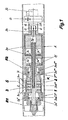
- a pipe joint 1, 2 of two pipes R1, R2 to be connected to one another via a weld seam S are mutually concentrically aligned and tensioned on the inside of the pipe ends with the aid of a so-called internal clamping device 3.
- the axis of the inner clamping device 3 is concentric with the axis of the pipe ends 1, 2.
- the inner clamping device 3 consists inter alia of a first tensioner head 3 * and a second tensioner head 3 **.
- the former consists of a wedge-shaped first inner part 3a *, which expands by axial displacement in a first outer part 3aa * latter in the radial direction.
- the first outer part 3aa * is composed of a plurality of segments distributed over the circumference, which are biased in the radial direction via two unspecified segments surrounding the segments.
- the second tensioner head 3 ** is constructed accordingly and has a second inner part 3a ** and a second outer part 3aa **.
- the inner part 3a ** continues in a substantially cylindrical extension 3ab **, on the other hand, and on the other hand, the first outer part 3aa * is axially supported on the other side.
- the first tensioner head 3 * is with a on the first inner part 3a * attacking and from a first drive piston 3c * driven first drive rod 3c connected.
- the second inner part 3a ** of the second tensioner head 3 ** via a second driven by a second drive piston 3d * Drive rod 3d shifted in the axial direction.
- the first and second drive pistons 3c * and 3d * are arranged in a drive cylinder A and can each on both sides with a via pressure medium holes 3e, 3f supplied Pressure medium D, for example compressed air, under certain conditions (for example Reduction of heat input by the cooling according to the invention) also with an incompressible pressure medium such as hydraulic oil, applied become.
- the inner clamping device 3 described above initially allows a Clamping and alignment of the left side with respect to the weld S shown Pipe end 1. Thereafter, the pipe end shown on the right side 2 are stretched, with the left side to the right side to Forming of the subsequently produced weld S used without a gap becomes.
- a Formiergasbohrung 3g is arranged, in the area between the clamping heads 3 *, 3 ** in one of the two Pipe ends 1 and 2 formed annular cooling and Formiergashunt K on the way over a transverse hole 3g *, a distribution chamber 3l and a Variety of distribution holes 3m opens.
- a particularly effective Distribution of the gas over the entire circumference and the entire length (heat affected zone Z) of the cooling and Formiergashunt K provides a fine-pored structured Distribution sleeve 3n sure that the extension 3ab ** in the area of exiting Distribution holes encloses 3m.
- About the forming gas hole 3g and the above-mentioned other flow path may be cooling forming gas G, possibly as cryogenic liquefied gas LG, the weld S during the Welding process to be supplied.
- the drive housing A is facing away from the clamping heads 3 *, 3 ** Front side connected to a shaft 3h, via which the pressure medium holes 3e and 3f and the Formiergasbohrung 3g introduced into the inner clamping device 3 become.
- the shaft 3h also carries on the outside one in their individual parts hereinafter unspecified image capture device B, with the finished Weld seam S after axial displacement of the inner clamping device 3 can be assessed visually.
- the shaft 3h sits beyond the image capture device B continues in a supply pipe 3i.
- the first and the second pipe end 1, 2 of the first and second pipe R1, R2 are on the inner clamping device 3, seen in the direction of the tube axis, from the two clamping heads 3 *, 3 ** with two in the axial Spaced apart rows of individual unspecified jaws and the drive cylinder A is so tight and aligned coaxially with each other, that in the region of the weld S to be generated, the arrangement shown in Figure 3 an end version 1 a, 2 a of the pipe ends 1, 2 given is.
- the second pipe R2 is welded in the form of a piece of pipe of a certain length to the first pipe R1, of which only the first pipe end 1 is shown, and that via this second pipe R2, the inner clamping device 3 to the to be connected to each other pipe ends 1, 2 is brought from the inside.
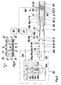
- the drive cylinder A terminates in the supply pipe 3i, through the conduit means are passed to the energy and gas supply, with a Coupling device 3k a Sammlerteil 7 through which the cryogenic liquefied Gas LG or its vapor or gaseous phase G is introduced, with the Supply pipe 3i is connected.
- the collector part 7 combines a gas line. 5 and a line for liquefied gas 6.
- the gas line 5 of the arrangement according to the invention takes its output at a first coupling 20a at the outlet of a Evaporator 20h of a reservoir and cold evaporator 20 for the cryogenic Liquid LG, and it leads, in the order of the subsequent naming, via a first overpressure safety valve 13, a first manual shut-off valve 11, a flow meter 15 in conjunction with a downstream Absperrund / or Throttle valve 15a and a first remote-controlled shut-off valve 9.
- Die Liquefied gas line 6 is connected to a liquid receiving line via a second coupling 20b 20i of the aforementioned reservoir and cold evaporator, 20 for cryogenic liquid LG connected, and it leads, in the subsequent order, via a second manual shut-off valve 12, a second overpressure safety valve 14 and a second remote-controlled shut-off valve 10.
- the structure of the reservoir and cryogenic liquid evaporator LG LG consists in a conventional manner from an inner container 20c for storing the cryogenic liquid LG, for example liquid nitrogen (LN 2 ) or liquid argon (LAr), an outer container 20d and an insulation 20e, the Room between inner and outer container 20c, 20d fills.
- the inner container 20c can be filled via a filling line 20f with the cryogenic liquid LN 2 or LAr. The latter is taken over a withdrawal line 20g.
- the reservoir and cold evaporator 20 is provided with a level indicator 20j and a pressure build-up means 20k.
- the cryogenic gas flows either as saturated steam or, with sufficient heat supply, as cold gas G via the gas line 5, the collector part 7 and the supply pipe 3i in the cooling and Formiergashunt K ( Figure 1) between the two Clamping heads 3 *, 3 ** in the area of the heat-affected zone Z (see FIG. 1) of the pipe ends 1, 2 to be connected to one another.
- a discharge from this area into the adjacent interior spaces of the pipes R1, R2 is via first and second outflow openings 3o * or 3o ** within the associated tensioner heads 3 *, 3 ** ensured.
- the arrangement according to the invention is associated with a first control unit 8.1, the supply of the cryogenic liquefied gas LG or the cryogenic gas in the cooling and Formiergashunt K controls.
- the control unit 8.1 is with the first and the second remote shut-off valve 9, 10 each via a he Ste or second control line 19a, 19b connected.
- she is about one first measuring line 18a with a device for temperature measurement 16 and via a second measuring line 18b with a display and switching device 17th (PISL: pressure display and switching when falling below a lower Pressure limit), which is arranged in the gas line 5 and at Fall below a given pressure or a given, directly measured flow the cooling on LPG and thus the Supply of the coolant to the line for liquefied gas 6 switches.
- PISL pressure display and switching when falling below a lower Pressure limit
- a second control unit 8.2 is provided, which on the one hand via a third control line 19c with a welding tool 4 and the andem via a signal processing line 19d to the first control unit 8.1 is connected.
- 3 are the candidate line sections with a highly effective thermal insulation provided.
- FIG. 3 shows the tube ends 1, 2 of a plated tube or a so-called BUBI tube consisting of a first and a second inner tube 1 'or 2' and a first and a second outer tube 1 "or 2".
- the connection of the inner tubes 1 'and 2' forms on the inside a root area W of the circumferential weld S, wherein the compound can be produced only by multi-layer welding due to the end version 1 a, 2 a of the pipe ends 1, 2 to be joined together.
- an unspecified and illustrated temperature measuring point 16a is positioned.
- FIG. 3 illustrates, optionally either on the side of the first pipe end 1 (temperature values ⁇ a *, ⁇ i *) or on the side of the second pipe end 2 (temperature values ⁇ a , ⁇ i ).
- the temperature measuring point 16a may be provided on the outside of the outer tube 1 ", 2" (temperature values ⁇ a , ⁇ a *) or on the inside of the inner tube 1 ', 2' (temperature values ⁇ i , ⁇ i *).
- deep-cold liquefied gas LG for example LN 2 or LAr
- LG is taken from the storage container and cold evaporator 20 and vaporized on the way via the evaporator 20 h.
- the resulting saturated steam or, if more heat is supplied, as necessary for evaporation, heated via the saturated steam temperature cold gas G flows through the gas line 5 into the cooling and Formiergashunt K, there to interconnect the inner tubes 1 ', 2' (or pipe ends 1, 2 in pipes R1, R2 with a homogeneous wall structure) to cool and then flow through the outflow openings 3o *, 3o ** in the two rows of clamping jaws of the clamping heads 3 *, 3 ** in the adjacent pipe interiors.
- the first control unit 8.1 will close the first remote-controlled shut-off valve 9, thereby increasing the temperature in the region of the pipe material that is near the weld.
- the first remote-controlled shut-off valve 9 is opened. Since the flow rate of the gas line 5 and this up to the reservoir and cold evaporator 20 upstream device is known, via the display and switching device 17 in conjunction with the means of temperature measurement 16 at the temperature measuring 16a, whether the cooling capacity by gas supply G. sufficient in the present application case. If this is not the case, then the first control unit 8.1 switches to the process variant II described below.
- deep-liquefied liquefied gas LG is withdrawn from the reservoir and cold evaporator 20 via the removal line 20g and fed directly to the liquid handling line 20i.
- the cryogenic liquefied gas LG passes via the line for liquefied gas 6 and the Sammlerteil 7 on the way via the supply pipe 3i in the above-described cooling and Formiergashunt K.
Landscapes
- Engineering & Computer Science (AREA)
- Physics & Mathematics (AREA)
- Mechanical Engineering (AREA)
- Optics & Photonics (AREA)
- Plasma & Fusion (AREA)
- Arc Welding In General (AREA)
- Butt Welding And Welding Of Specific Article (AREA)
- Heat Treatment Of Articles (AREA)
- Non-Disconnectible Joints And Screw-Threaded Joints (AREA)
Description
- Figur 1
- einen Mittelschnitt durch einen wesentlichen Teil einer Anordnung gemäß der Erfindung im Bereich beiderseits einer Rundschweißnaht;
- Figur 2
- eine schematische Darstellung der erfindungsgemäßen Anordnung in Verbindung mit einem an sich bekannten Vorratsbehälter und Kaltverdampfer für kryogene Flüssigkeit und
- Figur 3
- eine in Figur 2 im Bereich der Rundschweißnaht mit "X" gekennzeichnete Einzelheit in vergrößerter Darstellung.
- 1
- erstes Rohrleitungsende
- 2
- zweites Rohrleitungsende
- 3
- Innenspannvorrichtung
- 3*
- erster Spannerkopf
- 3a*
- erster Innenteil
- 3aa*
- erster Außenteil
- 3**
- zweiter Spannerkopf
- 3a**
- zweiter Innenteil
- 3ab**
- Verlängerung
- 3aa**
- zweiter Außenteil
- 3c
- erste Antriebsstange
- 3c*
- erster Antriebskolben
- 3d
- zweite Antriebsstange
- 3d*
- zweiter Antriebskolben
- 3e
- erste Druckmittelbohrung
- 3f
- zweite Druckmittelbohrung
- 3g
- Formiergasbohrung
- 3g*
- Querbohrung
- 3h
- Schaft
- 3i
- Versorgungsrohr
- 3k
- Kupplungsvorrichtung
- 3l
- Verteilungskammer
- 3m
- Verteilungsbohrung
- 3n
- feinporig strukturierte Verteilungshülse (Sintermetall)
- 3o*
- erste Abströmöffnungen
- 3o**
- zweite Abströmöffnungen
- 4
- Schweißwerkzeug
- 5
- Gasleitung
- 6
- Leitung für Flüssiggas
- 7
- Sammlerteil
- 8.1
- erste Steuereinheit (Gaszufuhr)
- 8.2
- zweite Steuereinheit (Schweißwerkzeug)
- 9
- erstes ferngesteuertes Absperrventil
- 10
- zweites femgesteuertes Absperrventil
- 11
- erstes Handabsperrventil
- 12
- zweites Handabsperrventil
- 13
- erstes Überdruck-Sicherheitsventil
- 14
- zweites Überdruck-Sicherheitsventil
- 15
- Durchflußmesser (z. B. Rotameter)
- 15a
- Ventil (Absperr- und/oder Drosselventil
- 16
- Einrichtung zur Temperaturmessung
- 16a
- Temperaturmeßstelle
- 17
- Anzeige- und Umschalteinrichtung
- 18a
- erste Meßleitung
- 18b
- zweite Meßleitung
- 19a
- erste Steuerleitung
- 19b
- zweite Steuerleitung
- 19c
- dritte Steuerleitung
- 19d
- Leitung für Signalverarbeitung
- 20
- Vorratsbehälter und Kaltverdampfer
- 20a
- erste Kupplung
- 20b
- zweite Kupplung
- 20c
- Innenbehälter
- 20d
- Außenbehälter
- 20e
- Isolierung
- 20f
- Füllleitung
- 20g
- Entnahmeleitung
- 20h
- Verdampfer
- 20i
- Flüssigentnahmeleitung
- 20j
- Einrichtung zur Füllstandsanzeige
- 20k
- Einrichtung zum Druckaufbau
- A
- Antriebszylinder
- B
- Bilderfassungseinrichtung
- D
- Druckmittel (z.B. Druckluft oder Hydrauliköl)
- G
- Formiergas
- K
- Kühl- und Formiergaskammer, ringförmig
- LG
- tiefkaltes verflüssigtes Gas (kryogene Flüssigkeit)
- LAr
- Flüssig-Argon
- LN2
- Flüssig-Stickstoff
- R1
- erste Rohrleitung
- R2
- zweite Rohrleitung
- S
- Schweißnaht
- Z
- Wärmeeinflußzone
- 1'
- erstes Innenrohr
- 2'
- zweites Innenrohr
- 1"
- erstes Außenrohr
- 2"
- zweites Außenrohr
- 1 a
- erste Endenausführung
- 2a
- zweite Endenausführung
- W
- Wurzelbereich
- ϑ
- Temperatur in der Wärmeeinflußzone Z
- ϑa ; ϑa*
- Temperatur an der Außenwand des Rohrleitungsendes
- ϑi ; ϑi*
- Temperatur an der Innenwand des Rohrleitungsendes
- ϑgo
- obere Grenztemperatur
- ϑgu
- untere Grenztemperatur
Claims (12)
- Verfahren zur Begrenzung der Temperatur beim Schweißen der Enden eines Rohrpaares im schweißnahtnahen Bereich des Rohrwerkstoffes, bei dem die miteinander zu verbindenden Rohrleitungsenden (1, 2) zweier Rohrleitungen (R1, R2) durch eine jeweils an der Innenseite der Rohrleitungsenden angreifende Innenspannvorrichtung (3) gegenseitig konzentrisch ausgerichtet und gespannt sind und sich die Achse der Innenspannvorrichtung konzentrisch zur Achse der Rohrleitungsenden ausrichtet, bei dem die innnenspannvorrichtung (3) zusammen mit den Rohrleitungsenden (1, 2) eine ringförmige Formiergaskammer (K) zur Beaufschlagung der Schweißnaht (S) mit einem Formiergas (G) bildet und begrenzt, bei dem der schweißnahtnahe Bereich des Rohrwerkstoffes im Bereich einer vom Schweißen bestimmten Wärmeeinflußzone (Z) mit dem Formiergas (G) beaufschlagt und damit gleichzeitig gekühlt wird, bei dem sich im Rohrwerkstoff der Wärmeeinflußzone (Z) eine Temperatur (ϑ) innerhalb eines durch eine obere und eine untere Grenztemperatur (ϑgo ; ϑgu) vorgegebenen Temperaturbereichs einstellt, bei dem das Formiergas (G) als kryogene Flüssigkeit (LG) bereitgestellt wird und bei dem ein auf der Außenseite der Rohrleitungen positioniertes Schweißwerkzeug (4) und die Rohrleitungen (R1, R2) eine auf die Achse der Rohrleitungen bezogene Rotationsbewegung relativ zueinander ausführen, dadurch gekennzeichnet,daß die Beaufschlagung mit Formiergas in gasförmigem Zustand unddaß die Kühlung der Wärmeeinflußzone (Z) in Abhängigkeit von der Temperatur (ϑ) geregelt erfolgen.
- Verfahren nach Anspruch 1, dadurch gekennzeichnet, daß die Kühlung der Wärmeeinflußzone (Z) mit dem Sattdampf (G) der kryogenen Flüssigkeit (LG) erfolgt.
- Verfahren nach Anspruch 1 oder 2, dadurch gekennzeichnet, daß bei der Kühlung der Wärmeeinflußzone (Z) die Verdampfungsenthalpie der kryogenen Flüssigkeit (LG) teilweise bis vollständig ausgenutzt wird (Verdampfungskühlung).
- Anordnung zur Durchführung des Verfahrens nach einem der Ansprüche 1 bis 3, mit einer Innenspannvorrichtung (3), die die miteinander zu verbindenden Rohrleitungsenden (1, 2) zweier Rohrleitungen (R1, R2) jeweils an der Innenseite der Rohrleitungsenden gegenseitig konzentrisch ausrichtet und spannt und die sich konzentrisch zur Achse der Rohrleitungsenden ausrichtet, mit einer zwischen einem ersten und einem zweiten Spannerkopf (3*, 3**) der Innenspannvorrichtung (3) gebildeten ringförmigen Formiergaskammer (K), in die einerseits Verteilungsbohrungen (3m) für Formiergas (G) ausmünden und die andererseits jeweils im Bereich zwischen der Innenspannvorrichtung (3) und der zugeordneten Rohrleitung (R1, R2) Abströmöffnungen (3o*, 3o**) aufweist, wobei die Formiergaskammer (K) der Bereitstellung der notwendigen Kühlleistung dient, außenseits von einer vom Schweißen bestimmten, beiderseits einer Schweißnaht (S) in den Rohrleitungsenden (1, 2) sich ausbreitenden Wärmeeinflußzone (Z) begrenzt wird, innenseits von einer zylindrischen Verlängerung (3ab**) begrenzt wird, die einerseits an einem den zweiten Spannerkopf (3**) spreizenden zweiten Innenteil (3a**) angeordnet ist und andererseits bis zum ersten Spannerkopf (3*) heranreicht und diesen axial abstützt, und die Formiergaskammer (K) sich jeweils beiderseits der Schweißnaht (S) in Richtung der Achse der Rohrleitung (R1, R2) über das zum jeweiligen Spannen der Rohrleitungsenden (1, 2) notwendige Abstandsmaß hinaus erstreckt, und mit einem auf der Außenseite der Rohrleitung positionierten Schweißwerkzeug (4), wobei letzteres und die Rohrleitungen (R1, R2) eine auf die Achse der Rohrleitungen bezogene Rotationsbewegung relativ zueinander ausführen, dadurch gekennzeichnet,daß im Bereich der Wärmeeinflußzone (Z) eine die Temperatur (ϑ) der Außen- oder Innenwand des Rohrleitungsendes (1, 2) erfassende Temperaturmeßstelle (16a) vorgesehen ist, unddaß Steuereinheiten (8.1, 8.2) über Messleitungen (18a, 18b) mit einer Einrichtung zur Temperaturmessung (16) an der Temperaturmessstelle (16a) und über Steuerteitungen (19a, 19b) mit Abspenventiten (9, 10) eines Vorratsbehäters und Kaltverdampfers (20) verbunden sind.
- Anordnung nach Anspruch 4, dadurch gekennzeichnet, daß die Kühl- und Formiergaskammer (K) innenseits von einer Verlängerung (3ab**) begrenzt ist, die eine in Richtung der Achse der Rohrleitung (R1, R2) orientierte, die Achse umschließende Verteilungskammer (3l) aufweist, von der Verteilungsbohrungen (3m) ausgehen, die sternförmig über den gesamten Umfang der Kühl- und Formiergaskammer (K) verteilt angeordnet sind und in letztere ausmünden.
- Anordnung nach Anspruch 4 oder 5, dadurch gekennzeichnet, daß Verlängerung (3ab**) im Bereich der austretenden Verteilungsbohrungen (3m) von einer feinporig strukturierten Verteilungshülse (3n) umschlossen ist.
- Anordnung nach einem der Ansprüche 4 bis 6, dadurch gekennzeichnet, daß das Formiergas (G) der Verteilungskammer (3l) über eine Formiergasbohrung (3g), die in einer einen Antriebszylinder (A) der Innenspannvorrichtung (3) und die Verteilungskammer (3l) durchdringenden ersten Antriebsstange (3c) angeordnet ist, zugeführt wird.
- Anordnung nach einem der Ansprüche 4 bis 7, dadurch gekennzeichnet, daß die Temperaturmeßstelle (16a) berührungsfrei arbeitend realisiert ist.
- Anordnung nach einem der Ansprüche 4 bis 8, dadurch gekennzeichnet, daß ein erster und ein zweiter Antriebskolben (3c*, 3d*) im Antriebszylinder (A) jeweils mit einer mit hydraulischem Druckmittel (D) beaufschlagbaren Profildichtung ausgestattet ist.
- Anordnung nach einem der Ansprüche 4 bis 9, dadurch gekennzeichnet, daß der in Form von Spannbacken ausgebildete jeweilige Außenteil (3aa*, 3aa**) des Spannerkopfes (3*, 3**) im Bereich seiner Kontaktflächen mit dem zugeordneten Rohrleitungsende (1, 2) und im Bereich seiner Laufftächen mit dem zugeordneten Innenteil (3a*, 3a**) eine Chrom-Polytetraflouräthylen-Beschichtung (Chrom-Teflon-Beschichtung) aufweist.
- Anordnung nach einem der Ansprüche 4 bis 10, dadurch gekennzeichnet, daß die Formiergasbohrung (3g) wahlweise mit einer Gasleitung (5) oder mit einer Leitung für Flüssiggas (6) verbunden ist, die beide in einem Vorratsbehätter und Kaltverdampfer (20) für kryogene Flüssigkeit (LG) enden.
- Anordnung nach einem der Ansprüche 4 bis 11, dadurch gekennzeichnet, daß die Verbindung zwischen dem Vorratsbehälter und Kaltverdampfer (20) und der Gasleitung (5) oder der Leitung für Flüssiggas (6), abhängig von der Temperatur (3) an der Temperaturmeßstelle (16a), über eine Einrichtung zur Temperaturmessung (16) gesteuert wird.
Priority Applications (1)
| Application Number | Priority Date | Filing Date | Title |
|---|---|---|---|
| DK01967096T DK1294529T3 (da) | 2000-06-27 | 2001-06-27 | Fremgangsmåde og indretning til ved svejsning af enderne af et rörpar ved hjælp af gas at begrænse temperaturen i rörmaterialet i området nær svejsesömmen |
Applications Claiming Priority (3)
| Application Number | Priority Date | Filing Date | Title |
|---|---|---|---|
| DE10030315 | 2000-06-27 | ||
| DE10030315 | 2000-06-27 | ||
| PCT/EP2001/007316 WO2002000385A1 (de) | 2000-06-27 | 2001-06-27 | Verfahren und anordnung zur begrenzung der temperatur beim schweissen der enden eines rohrpaares im schweissnahtnahen bereich des rohrwerkstoffes mittels gas |
Publications (3)
| Publication Number | Publication Date |
|---|---|
| EP1294529A1 EP1294529A1 (de) | 2003-03-26 |
| EP1294529B1 true EP1294529B1 (de) | 2005-05-25 |
| EP1294529B8 EP1294529B8 (de) | 2005-08-03 |
Family
ID=7646354
Family Applications (1)
| Application Number | Title | Priority Date | Filing Date |
|---|---|---|---|
| EP01967096A Expired - Lifetime EP1294529B8 (de) | 2000-06-27 | 2001-06-27 | Verfahren und anordnung zur begrenzung der temperatur beim schweissen der enden eines rohrpaares im schweissnahtnahen bereich des rohrwerkstoffes mittels gas |
Country Status (4)
| Country | Link |
|---|---|
| EP (1) | EP1294529B8 (de) |
| AT (1) | ATE296183T1 (de) |
| DE (1) | DE50106327D1 (de) |
| WO (1) | WO2002000385A1 (de) |
Cited By (2)
| Publication number | Priority date | Publication date | Assignee | Title |
|---|---|---|---|---|
| DE102006033992A1 (de) * | 2006-01-23 | 2007-08-02 | Schmidt + Clemens Gmbh + Co. Kg | Schweißverfahren |
| CN104690478A (zh) * | 2015-03-10 | 2015-06-10 | 洛阳德平科技股份有限公司 | 一种内对口器 |
Families Citing this family (15)
| Publication number | Priority date | Publication date | Assignee | Title |
|---|---|---|---|---|
| DE10057031C1 (de) * | 2000-11-17 | 2002-05-23 | Werner Jankus | Vorrichtung für die Innenzentrierung von miteinander zu verschweißenden Rohrstößen |
| DE102005014833A1 (de) * | 2005-03-30 | 2006-10-05 | Westfalen Ag | Verfahren zum Schweissen von Metallen |
| DE102007058804A1 (de) * | 2007-12-06 | 2009-06-10 | Linde Ag | Formiervorrichtung sowie Verfahren zum Formieren |
| US8662374B2 (en) * | 2010-12-16 | 2014-03-04 | Air Liquide Industrial U.S. Lp | Method for reduced cycle times in multi-pass welding while providing an inert atmosphere to the welding zone |
| GB2502130A (en) * | 2012-05-17 | 2013-11-20 | Acergy France Sa | Improvements relating to pipe welding |
| US9821415B2 (en) * | 2014-03-28 | 2017-11-21 | Crc-Evans Pipeline International, Inc. | Internal pipeline cooler |
| US10480862B2 (en) | 2013-05-23 | 2019-11-19 | Crc-Evans Pipeline International, Inc. | Systems and methods for use in welding pipe segments of a pipeline |
| US10695876B2 (en) | 2013-05-23 | 2020-06-30 | Crc-Evans Pipeline International, Inc. | Self-powered welding systems and methods |
| US11767934B2 (en) | 2013-05-23 | 2023-09-26 | Crc-Evans Pipeline International, Inc. | Internally welded pipes |
| US10589371B2 (en) | 2013-05-23 | 2020-03-17 | Crc-Evans Pipeline International, Inc. | Rotating welding system and methods |
| US10040141B2 (en) | 2013-05-23 | 2018-08-07 | Crc-Evans Pipeline International, Inc. | Laser controlled internal welding machine for a pipeline |
| CN104439872B (zh) * | 2013-09-25 | 2016-06-15 | 哈尔滨电气动力装备有限公司 | 用于大型圆筒形工件加工及装配的工装装置 |
| MX371071B (es) | 2014-08-29 | 2020-01-15 | Crc Evans Pipeline Int Inc Star | Método y sistema de soldadura. |
| US11458571B2 (en) | 2016-07-01 | 2022-10-04 | Crc-Evans Pipeline International, Inc. | Systems and methods for use in welding pipe segments of a pipeline |
| CN113245678B (zh) * | 2021-06-18 | 2021-10-08 | 招商局重工(江苏)有限公司 | 一种适用于管道氩弧焊的充氩密封保护装置 |
Family Cites Families (8)
| Publication number | Priority date | Publication date | Assignee | Title |
|---|---|---|---|---|
| US3784778A (en) * | 1968-12-09 | 1974-01-08 | Ca Atomic Energy Ltd | Method and apparatus for t. i. g. tube welding |
| US4712720A (en) * | 1985-03-14 | 1987-12-15 | Klaus Tesch | Device for mutually centering and clamping two pipe bodies to be welded to one another |
| DE9005893U1 (de) * | 1990-05-22 | 1990-09-06 | Kalberg, Friedel Paul, 2000 Barsbüttel | Ausricht- und Spannvorrichtung für die Enden eines Rohrteilpaares |
| DE4017886A1 (de) * | 1990-06-02 | 1991-12-05 | Austenit Ges Fuer Schweisstech | Formiergasgeraet |
| WO1995023669A1 (de) * | 1994-03-01 | 1995-09-08 | Siemens Aktiengesellschaft | Verfahren zum schweissen von metallischen werkstücken und vorrichtung zum durchführen des verfahrens |
| DE29700159U1 (de) * | 1996-01-24 | 1997-05-22 | Kalberg, Friedel Paul, 22885 Barsbüttel | Innenspannvorrichtung zum gegenseitigen Ausrichten und Spannen der miteinander zu verschweißenden Enden eines Rohrpaares |
| JP3327514B2 (ja) * | 1997-03-13 | 2002-09-24 | 住友金属工業株式会社 | 電縫鋼管のガスシールド溶接装置 |
| DE19713300C1 (de) * | 1997-03-29 | 1998-05-20 | Matthias Busch | Schutzgas-Orbitalschweißverfahren zur Erzeugung von Druckspannungen bei Verbindungsschweißungen |
-
2001
- 2001-06-27 EP EP01967096A patent/EP1294529B8/de not_active Expired - Lifetime
- 2001-06-27 WO PCT/EP2001/007316 patent/WO2002000385A1/de not_active Ceased
- 2001-06-27 AT AT01967096T patent/ATE296183T1/de not_active IP Right Cessation
- 2001-06-27 DE DE50106327T patent/DE50106327D1/de not_active Expired - Fee Related
Cited By (3)
| Publication number | Priority date | Publication date | Assignee | Title |
|---|---|---|---|---|
| DE102006033992A1 (de) * | 2006-01-23 | 2007-08-02 | Schmidt + Clemens Gmbh + Co. Kg | Schweißverfahren |
| CN104690478A (zh) * | 2015-03-10 | 2015-06-10 | 洛阳德平科技股份有限公司 | 一种内对口器 |
| CN104690478B (zh) * | 2015-03-10 | 2016-02-24 | 洛阳德平科技股份有限公司 | 一种内对口器 |
Also Published As
| Publication number | Publication date |
|---|---|
| EP1294529A1 (de) | 2003-03-26 |
| WO2002000385A1 (de) | 2002-01-03 |
| ATE296183T1 (de) | 2005-06-15 |
| EP1294529B8 (de) | 2005-08-03 |
| DE50106327D1 (de) | 2005-06-30 |
Similar Documents
| Publication | Publication Date | Title |
|---|---|---|
| EP1294529B1 (de) | Verfahren und anordnung zur begrenzung der temperatur beim schweissen der enden eines rohrpaares im schweissnahtnahen bereich des rohrwerkstoffes mittels gas | |
| DE3733243C2 (de) | ||
| EP0205828B1 (de) | Verfahren und Verwendung eines Stahles zur Herstellung von Stahlrohren mit erhöhter Sauergasbeständigkeit | |
| DE1575639C3 (de) | Walze und Verfahren zum Herstellen derselben | |
| EP2151652B1 (de) | Verbindungsstück zwischen einem Spaltrohr und einem Kühlrohr sowie ein Verfahren zum Verbinden eines Spaltrohres mit einem Kühlrohr | |
| EP0761345A2 (de) | Warmkammer-Druckgiessmaschine | |
| DE4439514C2 (de) | Kühlvorrichtung | |
| EP0040267A1 (de) | Gekühlter Leitschaufelträger | |
| DE548576C (de) | Verfahren zur Herstellung von eisernen Hochdruckrohren | |
| EP1367351B1 (de) | Wärmetauscher | |
| DE2743380C2 (de) | Kühlplatte für metallurgische, mit einer feuerfesten Auskleidung versehene Öfen, wie Hochöfen | |
| DE102005002618A1 (de) | Verfahren und Anordnung zur Begrenzung der Temperatur beim Schweißen der Enden eines Rohrpaares im schweißnahtnahen Bereich eines dünnwandigen Rohrwerkstoffes | |
| DE10160902A1 (de) | Reinigen von Objekten mit Flüssiggas | |
| EP0171558B1 (de) | Wärmeübertrager | |
| DE4242395B4 (de) | Verfahren und Vorrichtung zum Strangpressen | |
| DE3614482C2 (de) | ||
| DE1000649B (de) | Verbindungsstelle fuer von einem heissen Medium durchflossene rohrfoermige Teile, die aus Werkstoffen verschiedener Ausdehnung bestehen | |
| DE29605743U1 (de) | Spannstück für miteinander zu verschweißende Rohrabschnitte | |
| DE19634681C2 (de) | Vorrichtung für eine Rohrschweißanlage | |
| DE2604595C3 (de) | Kühlrohr zum Kühlen von Walzdraht | |
| DE3306579C2 (de) | Drahtführungsvorrichtung, insbesondere für Metalldraht von vorzugsweise Rundprofil | |
| AT411396B (de) | Wärmetauscher und verfahren zum anschweissen von wärmetauscherrohren an einer rohrplatte | |
| EP4623262A1 (de) | Wärmetauscher | |
| DE2710318A1 (de) | Walze, insbesondere fuer stranggiessanlagen | |
| DE208746C (de) |
Legal Events
| Date | Code | Title | Description |
|---|---|---|---|
| PUAI | Public reference made under article 153(3) epc to a published international application that has entered the european phase |
Free format text: ORIGINAL CODE: 0009012 |
|
| 17P | Request for examination filed |
Effective date: 20030115 |
|
| AK | Designated contracting states |
Kind code of ref document: A1 Designated state(s): AT BE CH CY DE DK ES FI FR GB GR IE IT LI LU MC NL PT SE TR |
|
| RAP1 | Party data changed (applicant data changed or rights of an application transferred) |
Owner name: WESTFALEN AG |
|
| RIN1 | Information on inventor provided before grant (corrected) |
Inventor name: WESTFALEN AG |
|
| GRAP | Despatch of communication of intention to grant a patent |
Free format text: ORIGINAL CODE: EPIDOSNIGR1 |
|
| GRAS | Grant fee paid |
Free format text: ORIGINAL CODE: EPIDOSNIGR3 |
|
| GRAA | (expected) grant |
Free format text: ORIGINAL CODE: 0009210 |
|
| AK | Designated contracting states |
Kind code of ref document: B1 Designated state(s): AT BE CH CY DE DK ES FI FR GB GR IE IT LI LU MC NL PT SE TR |
|
| PG25 | Lapsed in a contracting state [announced via postgrant information from national office to epo] |
Ref country code: TR Free format text: LAPSE BECAUSE OF FAILURE TO SUBMIT A TRANSLATION OF THE DESCRIPTION OR TO PAY THE FEE WITHIN THE PRESCRIBED TIME-LIMIT Effective date: 20050525 Ref country code: FI Free format text: LAPSE BECAUSE OF FAILURE TO SUBMIT A TRANSLATION OF THE DESCRIPTION OR TO PAY THE FEE WITHIN THE PRESCRIBED TIME-LIMIT Effective date: 20050525 Ref country code: IE Free format text: LAPSE BECAUSE OF FAILURE TO SUBMIT A TRANSLATION OF THE DESCRIPTION OR TO PAY THE FEE WITHIN THE PRESCRIBED TIME-LIMIT Effective date: 20050525 Ref country code: ES Free format text: LAPSE BECAUSE OF FAILURE TO SUBMIT A TRANSLATION OF THE DESCRIPTION OR TO PAY THE FEE WITHIN THE PRESCRIBED TIME-LIMIT Effective date: 20050525 Ref country code: GB Free format text: LAPSE BECAUSE OF FAILURE TO SUBMIT A TRANSLATION OF THE DESCRIPTION OR TO PAY THE FEE WITHIN THE PRESCRIBED TIME-LIMIT Effective date: 20050525 |
|
| REG | Reference to a national code |
Ref country code: GB Ref legal event code: FG4D Free format text: NOT ENGLISH |
|
| REG | Reference to a national code |
Ref country code: CH Ref legal event code: EP |
|
| REG | Reference to a national code |
Ref country code: CH Ref legal event code: NV Representative=s name: ARIE WUBBEN Ref country code: IE Ref legal event code: FG4D Free format text: LANGUAGE OF EP DOCUMENT: GERMAN |
|
| PG25 | Lapsed in a contracting state [announced via postgrant information from national office to epo] |
Ref country code: CY Free format text: LAPSE BECAUSE OF FAILURE TO SUBMIT A TRANSLATION OF THE DESCRIPTION OR TO PAY THE FEE WITHIN THE PRESCRIBED TIME-LIMIT Effective date: 20050627 |
|
| PG25 | Lapsed in a contracting state [announced via postgrant information from national office to epo] |
Ref country code: MC Free format text: LAPSE BECAUSE OF NON-PAYMENT OF DUE FEES Effective date: 20050630 |
|
| REF | Corresponds to: |
Ref document number: 50106327 Country of ref document: DE Date of ref document: 20050630 Kind code of ref document: P |
|
| RIN2 | Information on inventor provided after grant (corrected) |
Inventor name: KALBERG, FRIEDEL PAUL |
|
| PG25 | Lapsed in a contracting state [announced via postgrant information from national office to epo] |
Ref country code: SE Free format text: LAPSE BECAUSE OF FAILURE TO SUBMIT A TRANSLATION OF THE DESCRIPTION OR TO PAY THE FEE WITHIN THE PRESCRIBED TIME-LIMIT Effective date: 20050825 Ref country code: GR Free format text: LAPSE BECAUSE OF FAILURE TO SUBMIT A TRANSLATION OF THE DESCRIPTION OR TO PAY THE FEE WITHIN THE PRESCRIBED TIME-LIMIT Effective date: 20050825 |
|
| REG | Reference to a national code |
Ref country code: DK Ref legal event code: T3 |
|
| PG25 | Lapsed in a contracting state [announced via postgrant information from national office to epo] |
Ref country code: PT Free format text: LAPSE BECAUSE OF FAILURE TO SUBMIT A TRANSLATION OF THE DESCRIPTION OR TO PAY THE FEE WITHIN THE PRESCRIBED TIME-LIMIT Effective date: 20051027 |
|
| GBV | Gb: ep patent (uk) treated as always having been void in accordance with gb section 77(7)/1977 [no translation filed] |
Effective date: 20050525 |
|
| REG | Reference to a national code |
Ref country code: IE Ref legal event code: FD4D |
|
| ET | Fr: translation filed | ||
| PLBE | No opposition filed within time limit |
Free format text: ORIGINAL CODE: 0009261 |
|
| STAA | Information on the status of an ep patent application or granted ep patent |
Free format text: STATUS: NO OPPOSITION FILED WITHIN TIME LIMIT |
|
| 26N | No opposition filed |
Effective date: 20060228 |
|
| PGFP | Annual fee paid to national office [announced via postgrant information from national office to epo] |
Ref country code: IT Payment date: 20060630 Year of fee payment: 6 |
|
| PGFP | Annual fee paid to national office [announced via postgrant information from national office to epo] |
Ref country code: CH Payment date: 20080613 Year of fee payment: 8 Ref country code: DK Payment date: 20080610 Year of fee payment: 8 Ref country code: LU Payment date: 20080613 Year of fee payment: 8 |
|
| PGFP | Annual fee paid to national office [announced via postgrant information from national office to epo] |
Ref country code: AT Payment date: 20080616 Year of fee payment: 8 |
|
| PGFP | Annual fee paid to national office [announced via postgrant information from national office to epo] |
Ref country code: DE Payment date: 20080827 Year of fee payment: 8 Ref country code: NL Payment date: 20080618 Year of fee payment: 8 |
|
| PGFP | Annual fee paid to national office [announced via postgrant information from national office to epo] |
Ref country code: FR Payment date: 20080613 Year of fee payment: 8 |
|
| PGFP | Annual fee paid to national office [announced via postgrant information from national office to epo] |
Ref country code: BE Payment date: 20080728 Year of fee payment: 8 |
|
| PG25 | Lapsed in a contracting state [announced via postgrant information from national office to epo] |
Ref country code: IT Free format text: LAPSE BECAUSE OF NON-PAYMENT OF DUE FEES Effective date: 20070627 |
|
| BERE | Be: lapsed |
Owner name: *WESTFALEN A.G. Effective date: 20090630 |
|
| REG | Reference to a national code |
Ref country code: CH Ref legal event code: PL |
|
| REG | Reference to a national code |
Ref country code: DK Ref legal event code: EBP |
|
| NLV4 | Nl: lapsed or anulled due to non-payment of the annual fee |
Effective date: 20100101 |
|
| REG | Reference to a national code |
Ref country code: FR Ref legal event code: ST Effective date: 20100226 |
|
| PG25 | Lapsed in a contracting state [announced via postgrant information from national office to epo] |
Ref country code: FR Free format text: LAPSE BECAUSE OF NON-PAYMENT OF DUE FEES Effective date: 20090630 Ref country code: CH Free format text: LAPSE BECAUSE OF NON-PAYMENT OF DUE FEES Effective date: 20090630 Ref country code: LI Free format text: LAPSE BECAUSE OF NON-PAYMENT OF DUE FEES Effective date: 20090630 |
|
| PG25 | Lapsed in a contracting state [announced via postgrant information from national office to epo] |
Ref country code: DE Free format text: LAPSE BECAUSE OF NON-PAYMENT OF DUE FEES Effective date: 20100101 Ref country code: BE Free format text: LAPSE BECAUSE OF NON-PAYMENT OF DUE FEES Effective date: 20090630 Ref country code: AT Free format text: LAPSE BECAUSE OF NON-PAYMENT OF DUE FEES Effective date: 20090627 |
|
| PG25 | Lapsed in a contracting state [announced via postgrant information from national office to epo] |
Ref country code: DK Free format text: LAPSE BECAUSE OF NON-PAYMENT OF DUE FEES Effective date: 20090630 Ref country code: NL Free format text: LAPSE BECAUSE OF NON-PAYMENT OF DUE FEES Effective date: 20100101 |
|
| PG25 | Lapsed in a contracting state [announced via postgrant information from national office to epo] |
Ref country code: LU Free format text: LAPSE BECAUSE OF NON-PAYMENT OF DUE FEES Effective date: 20090627 |