EP1294529B1 - Method and device for limiting temperature using gas, when welding the ends of two tubes, in the region of the tube material close to the weld seam - Google Patents
Method and device for limiting temperature using gas, when welding the ends of two tubes, in the region of the tube material close to the weld seam Download PDFInfo
- Publication number
- EP1294529B1 EP1294529B1 EP01967096A EP01967096A EP1294529B1 EP 1294529 B1 EP1294529 B1 EP 1294529B1 EP 01967096 A EP01967096 A EP 01967096A EP 01967096 A EP01967096 A EP 01967096A EP 1294529 B1 EP1294529 B1 EP 1294529B1
- Authority
- EP
- European Patent Office
- Prior art keywords
- temperature
- forming gas
- region
- welding
- gas
- Prior art date
- Legal status (The legal status is an assumption and is not a legal conclusion. Google has not performed a legal analysis and makes no representation as to the accuracy of the status listed.)
- Expired - Lifetime
Links
Images
Classifications
-
- B—PERFORMING OPERATIONS; TRANSPORTING
- B23—MACHINE TOOLS; METAL-WORKING NOT OTHERWISE PROVIDED FOR
- B23K—SOLDERING OR UNSOLDERING; WELDING; CLADDING OR PLATING BY SOLDERING OR WELDING; CUTTING BY APPLYING HEAT LOCALLY, e.g. FLAME CUTTING; WORKING BY LASER BEAM
- B23K9/00—Arc welding or cutting
- B23K9/32—Accessories
- B23K9/325—Devices for supplying or evacuating shielding gas
-
- B—PERFORMING OPERATIONS; TRANSPORTING
- B23—MACHINE TOOLS; METAL-WORKING NOT OTHERWISE PROVIDED FOR
- B23K—SOLDERING OR UNSOLDERING; WELDING; CLADDING OR PLATING BY SOLDERING OR WELDING; CUTTING BY APPLYING HEAT LOCALLY, e.g. FLAME CUTTING; WORKING BY LASER BEAM
- B23K37/00—Auxiliary devices or processes, not specially adapted to a procedure covered by only one of the preceding main groups
- B23K37/003—Cooling means
-
- B—PERFORMING OPERATIONS; TRANSPORTING
- B23—MACHINE TOOLS; METAL-WORKING NOT OTHERWISE PROVIDED FOR
- B23K—SOLDERING OR UNSOLDERING; WELDING; CLADDING OR PLATING BY SOLDERING OR WELDING; CUTTING BY APPLYING HEAT LOCALLY, e.g. FLAME CUTTING; WORKING BY LASER BEAM
- B23K37/00—Auxiliary devices or processes, not specially adapted to a procedure covered by only one of the preceding main groups
- B23K37/04—Auxiliary devices or processes, not specially adapted to a procedure covered by only one of the preceding main groups for holding or positioning work
- B23K37/053—Auxiliary devices or processes, not specially adapted to a procedure covered by only one of the preceding main groups for holding or positioning work aligning cylindrical work; Clamping devices therefor
- B23K37/0531—Auxiliary devices or processes, not specially adapted to a procedure covered by only one of the preceding main groups for holding or positioning work aligning cylindrical work; Clamping devices therefor internal pipe alignment clamps
Definitions
- the invention relates to a method for limiting the temperature Welding the ends of a pipe pair in the welding area near the Pipe material according to the preamble of claim 1 and an arrangement for Performing the method according to the preamble of the independent claim. 6
- Corrosion-resistant steels with fully austenitic microstructure for example in the food and beverage industry, chemistry or pharmacy in the form of tubes are used and with each other often have to be welded in welding area close of the pipe material an inadmissibly high heating, the structural change causes in this area and thereby the pipes in the area Weld makes corrosion susceptible. A high heat load in the area The round weld must therefore be avoided for the aforementioned reason.
- a third solution in this regard provides in this context, Strength, corrosion resistance and economy thereby in one another
- BUBI tube is a corrosion resistant pipe drawn into a ferritic pipe and with the help of an expansion and Kalibrierpresse pressed.
- the inner tube is first elastic, then plastically widened between about 2 and 5% until it starts the inner wall of the outer tube rests. Then there is a common Expansion of the inner and outer tube by about 0.5 to 1% instead, where the outer tube is held by a two-part outer tool.
- WO 86 05430 A describes a device for mutual centering and clamping of two pipe bodies to be welded together. which together with the pipe ends forms and limits an annular forming gas chamber for acting on the weld seam with a forming gas.
- the device has a clamping unit for each of the tubular bodies on both sides of the forming gas chamber provided with inert gas supply, which comprises at least one circumferential row of tendons contained in a clamping groove, which can be tensioned outwardly by mutual axial approximation or removal of the flanks of the clamping groove.
- the supplied forming gas is intended to prevent oxidation of the weld and thus the welding of a non-binding and corrosion-resistant Allow weld and their adjacent areas.
- the both sides over Tendons flowing off forming gas also reduces the incidence of heat the inner clamping device, said cooling on the one hand on the tendons and on the other hand, on the pipe inner surface, from the essential thermal effects go out on these tendons, is directed.
- WO 95 23669 A a method for welding, in particular joint welding of metallic materials and a device for carrying out the method is known, with or with the low effort in the region of the weld during welding, a high temperature gradient over the wall thickness of the workpieces can be achieved. To generate this temperature gradient, the workpieces are cooled during welding with liquefied gas.
- the device has a tube to be connected to the inside (workpieces) insertable spray device connected to a supply line for LPG and provided with at least one outlet opening.
- the area to be cooled The weld is essentially by two disc-shaped baffles which borders the area to be cooled very closely on the root area of the Limit weld.
- the procedural solution is that when welding such Rounded seams required forming gas, which is the oxidation of the weld prevented and from the inside of the tube to the weld in its root area is used, is used at the same time for cooling the welding seam near Area of the pipe material in the area of one determined by welding Heat affected zone, so that in the pipe material of the heat affected zone a temperature within one of an upper and a lower limit temperature set temperature range.
- this is the Usually not provided at room temperature forming gas, since its energy absorption capacity, i.
- the solution is firstly that the forming gas, for example nitrogen or argon, as a cryogenic liquefied gas.
- the forming gas for example nitrogen or argon
- This is the total enthalpy of the gas from its boiling temperature at the corresponding Supply pressure in the liquid phase up to an upper temperature in the gas phase, due to the necessary heat transfer at least something below the temperature to be maintained, exploitable.
- the first variant is the cryogenic liquefied gas from a so-called reservoir and cold evaporator for cryogenic liquid and evaporate in an external evaporator.
- the so produced saturated steam leaves about with boiling temperature, for example, for a Ambient pressure of about 1 bar for nitrogen at about 77 K (Kelvin) and for Argon is at about 87 K, the evaporator and is at about this temperature also introduced into the proposed arrangement.
- cryogenic liquefied gas will indeed make its way into the area close to the weld evaporate, but then there is a forming gas available in each Trap has a lower temperature than that of a feed of the invention Arrangement with forming gas in the gaseous phase is the case. This results from the fact that the guided over the evaporator cryogenic Liquid there already provides their enthalpy of vaporization without these for cooling the weld seam or areas heated near the welding area could be used the inventive arrangement.
- the inventive method is designed such that the temperature in weld area near the pipe material continuously measured and a Control is transmitted. At the same time, the form of the Gas flow measured in the gas line. When falling below a lower Limit pressure, the cooling is switched to LPG. alternative For this purpose, a flow measurement in the gas line is provided. To this Way, it is possible for the controller to determine if over an intensification of the Gas supply an intensification of the cooling is possible or whether the arrangement to switch to increase their cooling capacity to LPG supply is.
- the pipe ends to be welded together are preferably clamped on the inside with the so-called inner clamping device and aligned coaxially with each other.
- a positioned on the outside of the pipes welding tool and the pipes perform a relative to the axis of the pipes rotational movement relative to each other.
- the inner clamping device two so-called clamping heads are provided, the clamping jaws are arranged on both sides of the weld circular and between them form an annular space, which is bounded on the tube side of the root portion of the weld (heat affected zone).
- Such an inner clamping device is described for example in the utility model DE-U-90 05 893 or in EP-B-0 215 868 .
- the aforementioned annular space between the clamping jaws within the circumferential weld is applied in a conventional manner in the course of production of the circumferential seam with the necessary forming gas, which is usually supplied in the region of the longitudinal axis (tube axis) of the inner clamping device latter and on both sides of the Circular seam, in each case via outflow openings of the gas-permeable clamping jaws, can flow.
- the proposed method now leads to this annular space described above between the tensioner heads, a cooling and forming gas chamber, the deep-cold Forming gas to, soft here then determined by welding, both sides the weld in the pipe ends propagating heat affected zone can cool intensively.
- the cooling and forming gas chamber is on the outside bounded by the heat-affected zone and internally bounded by a substantially cylindrical extension, on the one hand to a second Clamping head expanding inner part is arranged and on the other hand to the first Clamping head reaches and supports this axially. This extends the Cooling and Formiergashunt each side of the weld in the direction of Axes of the pipeline above that for respective clamping of the pipe ends necessary distance measure beyond.
- Cooling and Formiergashunt Distribution holes for forming gas out in the extension are arranged, and there are each in the area between the tensioner head and provided the associated pipe outflow openings.
- Adequate cooling of the heat affected zone is ensured by a good and trouble-free Supply of cooling forming gas ensured.
- the extension an oriented in the direction of the axis of the pipeline, the axis enclosing Distribution chamber, starting from the distribution holes, the distributed in a star shape over the entire circumference of the cooling and Formiergashunt are arranged and terminate in the latter.
- the distribution will be further improved and, on the other hand, that of the Heat affected zone outgoing heat radiation very effective in the forming gas introduced, if the latter before exiting into the cooling and Formiergashunt flows through a fine-pored structured distribution sleeve, which, as another Proposal provides for the extension in the area of emerging distribution wells encloses.
- the forming gas of the distribution chamber via a Formiergasbohrung, in a drive cylinder the inner jig and the distribution chamber penetrating the first Drive rod is arranged is supplied.
- This will cause the drive cylinder cooled with its drive piston from the inside, so that from the area the weld seam externally acting on the drive cylinder heat accumulation To counteract inadmissible temperature increases effectively counteracted can be.
- This quasi cooled from inside drive cylinder can then in advantageously be acted upon with hydraulic pressure medium.
- another proposal provides that the drive piston in the drive cylinder each acted upon by a hydraulic pressure medium Profile seal are equipped.
- the inlet temperature of the cryogenic forming gas in the inner clamping device can be changed within limits, so that the temperature in the critical area near the welding area of the pipe material below one is to be kept predetermined upper temperature limit.
- the cooling is included to control such that a lower temperature limit also not fallen below is because such a fall below the quality of the round seam and so that the pipe connection would also adversely affect.
- a lower temperature limit also not fallen below is because such a fall below the quality of the round seam and so that the pipe connection would also adversely affect.
- the Formiergasbohrung optionally connected to a gas line or to a line for liquefied gas is, both in the reservoir and cold evaporator for cryogenic liquid end up.
- This is the connection between the reservoir and cold evaporator and the gas line or the line for liquefied gas, as it continues to do is provided, depending on the temperature at the temperature measuring over a device for temperature measurement controlled.
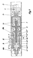
- a pipe joint 1, 2 of two pipes R1, R2 to be connected to one another via a weld seam S are mutually concentrically aligned and tensioned on the inside of the pipe ends with the aid of a so-called internal clamping device 3.
- the axis of the inner clamping device 3 is concentric with the axis of the pipe ends 1, 2.
- the inner clamping device 3 consists inter alia of a first tensioner head 3 * and a second tensioner head 3 **.
- the former consists of a wedge-shaped first inner part 3a *, which expands by axial displacement in a first outer part 3aa * latter in the radial direction.
- the first outer part 3aa * is composed of a plurality of segments distributed over the circumference, which are biased in the radial direction via two unspecified segments surrounding the segments.
- the second tensioner head 3 ** is constructed accordingly and has a second inner part 3a ** and a second outer part 3aa **.
- the inner part 3a ** continues in a substantially cylindrical extension 3ab **, on the other hand, and on the other hand, the first outer part 3aa * is axially supported on the other side.
- the first tensioner head 3 * is with a on the first inner part 3a * attacking and from a first drive piston 3c * driven first drive rod 3c connected.
- the second inner part 3a ** of the second tensioner head 3 ** via a second driven by a second drive piston 3d * Drive rod 3d shifted in the axial direction.
- the first and second drive pistons 3c * and 3d * are arranged in a drive cylinder A and can each on both sides with a via pressure medium holes 3e, 3f supplied Pressure medium D, for example compressed air, under certain conditions (for example Reduction of heat input by the cooling according to the invention) also with an incompressible pressure medium such as hydraulic oil, applied become.
- the inner clamping device 3 described above initially allows a Clamping and alignment of the left side with respect to the weld S shown Pipe end 1. Thereafter, the pipe end shown on the right side 2 are stretched, with the left side to the right side to Forming of the subsequently produced weld S used without a gap becomes.
- a Formiergasbohrung 3g is arranged, in the area between the clamping heads 3 *, 3 ** in one of the two Pipe ends 1 and 2 formed annular cooling and Formiergashunt K on the way over a transverse hole 3g *, a distribution chamber 3l and a Variety of distribution holes 3m opens.
- a particularly effective Distribution of the gas over the entire circumference and the entire length (heat affected zone Z) of the cooling and Formiergashunt K provides a fine-pored structured Distribution sleeve 3n sure that the extension 3ab ** in the area of exiting Distribution holes encloses 3m.
- About the forming gas hole 3g and the above-mentioned other flow path may be cooling forming gas G, possibly as cryogenic liquefied gas LG, the weld S during the Welding process to be supplied.
- the drive housing A is facing away from the clamping heads 3 *, 3 ** Front side connected to a shaft 3h, via which the pressure medium holes 3e and 3f and the Formiergasbohrung 3g introduced into the inner clamping device 3 become.
- the shaft 3h also carries on the outside one in their individual parts hereinafter unspecified image capture device B, with the finished Weld seam S after axial displacement of the inner clamping device 3 can be assessed visually.
- the shaft 3h sits beyond the image capture device B continues in a supply pipe 3i.
- the first and the second pipe end 1, 2 of the first and second pipe R1, R2 are on the inner clamping device 3, seen in the direction of the tube axis, from the two clamping heads 3 *, 3 ** with two in the axial Spaced apart rows of individual unspecified jaws and the drive cylinder A is so tight and aligned coaxially with each other, that in the region of the weld S to be generated, the arrangement shown in Figure 3 an end version 1 a, 2 a of the pipe ends 1, 2 given is.
- the second pipe R2 is welded in the form of a piece of pipe of a certain length to the first pipe R1, of which only the first pipe end 1 is shown, and that via this second pipe R2, the inner clamping device 3 to the to be connected to each other pipe ends 1, 2 is brought from the inside.
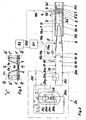
- the drive cylinder A terminates in the supply pipe 3i, through the conduit means are passed to the energy and gas supply, with a Coupling device 3k a Sammlerteil 7 through which the cryogenic liquefied Gas LG or its vapor or gaseous phase G is introduced, with the Supply pipe 3i is connected.
- the collector part 7 combines a gas line. 5 and a line for liquefied gas 6.
- the gas line 5 of the arrangement according to the invention takes its output at a first coupling 20a at the outlet of a Evaporator 20h of a reservoir and cold evaporator 20 for the cryogenic Liquid LG, and it leads, in the order of the subsequent naming, via a first overpressure safety valve 13, a first manual shut-off valve 11, a flow meter 15 in conjunction with a downstream Absperrund / or Throttle valve 15a and a first remote-controlled shut-off valve 9.
- Die Liquefied gas line 6 is connected to a liquid receiving line via a second coupling 20b 20i of the aforementioned reservoir and cold evaporator, 20 for cryogenic liquid LG connected, and it leads, in the subsequent order, via a second manual shut-off valve 12, a second overpressure safety valve 14 and a second remote-controlled shut-off valve 10.
- the structure of the reservoir and cryogenic liquid evaporator LG LG consists in a conventional manner from an inner container 20c for storing the cryogenic liquid LG, for example liquid nitrogen (LN 2 ) or liquid argon (LAr), an outer container 20d and an insulation 20e, the Room between inner and outer container 20c, 20d fills.
- the inner container 20c can be filled via a filling line 20f with the cryogenic liquid LN 2 or LAr. The latter is taken over a withdrawal line 20g.
- the reservoir and cold evaporator 20 is provided with a level indicator 20j and a pressure build-up means 20k.
- the cryogenic gas flows either as saturated steam or, with sufficient heat supply, as cold gas G via the gas line 5, the collector part 7 and the supply pipe 3i in the cooling and Formiergashunt K ( Figure 1) between the two Clamping heads 3 *, 3 ** in the area of the heat-affected zone Z (see FIG. 1) of the pipe ends 1, 2 to be connected to one another.
- a discharge from this area into the adjacent interior spaces of the pipes R1, R2 is via first and second outflow openings 3o * or 3o ** within the associated tensioner heads 3 *, 3 ** ensured.
- the arrangement according to the invention is associated with a first control unit 8.1, the supply of the cryogenic liquefied gas LG or the cryogenic gas in the cooling and Formiergashunt K controls.
- the control unit 8.1 is with the first and the second remote shut-off valve 9, 10 each via a he Ste or second control line 19a, 19b connected.
- she is about one first measuring line 18a with a device for temperature measurement 16 and via a second measuring line 18b with a display and switching device 17th (PISL: pressure display and switching when falling below a lower Pressure limit), which is arranged in the gas line 5 and at Fall below a given pressure or a given, directly measured flow the cooling on LPG and thus the Supply of the coolant to the line for liquefied gas 6 switches.
- PISL pressure display and switching when falling below a lower Pressure limit
- a second control unit 8.2 is provided, which on the one hand via a third control line 19c with a welding tool 4 and the andem via a signal processing line 19d to the first control unit 8.1 is connected.
- 3 are the candidate line sections with a highly effective thermal insulation provided.
- FIG. 3 shows the tube ends 1, 2 of a plated tube or a so-called BUBI tube consisting of a first and a second inner tube 1 'or 2' and a first and a second outer tube 1 "or 2".
- the connection of the inner tubes 1 'and 2' forms on the inside a root area W of the circumferential weld S, wherein the compound can be produced only by multi-layer welding due to the end version 1 a, 2 a of the pipe ends 1, 2 to be joined together.
- an unspecified and illustrated temperature measuring point 16a is positioned.
- FIG. 3 illustrates, optionally either on the side of the first pipe end 1 (temperature values ⁇ a *, ⁇ i *) or on the side of the second pipe end 2 (temperature values ⁇ a , ⁇ i ).
- the temperature measuring point 16a may be provided on the outside of the outer tube 1 ", 2" (temperature values ⁇ a , ⁇ a *) or on the inside of the inner tube 1 ', 2' (temperature values ⁇ i , ⁇ i *).
- deep-cold liquefied gas LG for example LN 2 or LAr
- LG is taken from the storage container and cold evaporator 20 and vaporized on the way via the evaporator 20 h.
- the resulting saturated steam or, if more heat is supplied, as necessary for evaporation, heated via the saturated steam temperature cold gas G flows through the gas line 5 into the cooling and Formiergashunt K, there to interconnect the inner tubes 1 ', 2' (or pipe ends 1, 2 in pipes R1, R2 with a homogeneous wall structure) to cool and then flow through the outflow openings 3o *, 3o ** in the two rows of clamping jaws of the clamping heads 3 *, 3 ** in the adjacent pipe interiors.
- the first control unit 8.1 will close the first remote-controlled shut-off valve 9, thereby increasing the temperature in the region of the pipe material that is near the weld.
- the first remote-controlled shut-off valve 9 is opened. Since the flow rate of the gas line 5 and this up to the reservoir and cold evaporator 20 upstream device is known, via the display and switching device 17 in conjunction with the means of temperature measurement 16 at the temperature measuring 16a, whether the cooling capacity by gas supply G. sufficient in the present application case. If this is not the case, then the first control unit 8.1 switches to the process variant II described below.
- deep-liquefied liquefied gas LG is withdrawn from the reservoir and cold evaporator 20 via the removal line 20g and fed directly to the liquid handling line 20i.
- the cryogenic liquefied gas LG passes via the line for liquefied gas 6 and the Sammlerteil 7 on the way via the supply pipe 3i in the above-described cooling and Formiergashunt K.
Abstract
Description
Die Erfindung betrifft ein Verfahren zur Begrenzung der Temperatur beim
Schweißen der Enden eines Rohrpaares im schweißnahtnahen Bereich des
Rohrwerkstoffes nach dem Oberbegriff des Anspruchs 1 und eine Anordnung zum
Durchführen des Verfahrens nach dem Oberbegriff des Nebenanspruchs 6.The invention relates to a method for limiting the temperature
Welding the ends of a pipe pair in the welding area near the
Pipe material according to the preamble of
Korrosionsbeständige Stähle mit voll austenitischem Gefügeaufbau, die beispielsweise im Bereich der Nahrungsmittel- und Getränkeindustrie, der Chemie oder Pharmazie in Form von Rohren zur Anwendung kommen und dabei miteinander verschweißt werden müssen, erfahren vielfach im schweißnahtnahen Bereich des Rohrwerkstoffes eine unzulässig hohe Erwärmung, die eine Gefügeveränderung in diesem Bereich hervorruft und dadurch die Rohre im Bereich der Schweißnaht korrosionsanfällig macht. Eine hohe Wärmebelastung im Bereich der Rundschweißnaht muß daher aus dem vorgenannten Grunde vermieden werden.Corrosion-resistant steels with fully austenitic microstructure, for example in the food and beverage industry, chemistry or pharmacy in the form of tubes are used and with each other often have to be welded in welding area close of the pipe material an inadmissibly high heating, the structural change causes in this area and thereby the pipes in the area Weld makes corrosion susceptible. A high heat load in the area The round weld must therefore be avoided for the aforementioned reason.
Es ist eine Vielzahl von Anwendungsfällen bekannt, bei denen eine Rohrleitung sowohl einem hohen innendruck des zu fördernden Fluides als auch einer Korrosionsbeanspruchung durch dieses Fluid ausgesetzt ist. Als Beispiel hierfür sei die Erdgasförderung mittels einer Pipeline genannt, in der das zu fördernde Erdgas in der bei der Förderung anfallenden Beschaffenheit und des dabei anstehenden Druckes ohne anschließende Trocknung gefördert wird. Dieses nasse und unter hohem Druck stehende Erdgas ist aufgrund seiner Zusammensetzung korrosiv. Es ist daher eine Rohrleitung erforderlich, die einerseits zumindest auf der Rohrinnenseite die notwendige Korrosionsbeständigkeit aufweist und die andererseits dem hohen Förderdruck standhalten muß. There are a variety of applications known in which a pipeline both a high internal pressure of the fluid to be pumped and a corrosion stress is exposed by this fluid. As an example of this is the Natural gas production by means of a pipeline, in which the natural gas to be extracted in the nature of the promotion and the upcoming costs Pressure is conveyed without subsequent drying. This wet and under High-pressure natural gas is corrosive due to its composition. It is therefore a pipe required, on the one hand at least on the inside of the pipe has the necessary corrosion resistance and the other must withstand the high delivery pressure.
Eine erste Lösung dieses Problems besteht in naheliegender Weise darin, das Rohr aus Festigkeitsgründen dickwandig auszuführen, wobei der verwendete Werkstoff insgesamt die notwendige Korrosionsbeständigkeit besitzen muß. Eine derartige Lösung scheidet in den meisten Fällen aber aus Kostengründen aus.An initial solution to this problem is obviously the Pipe for strength reasons thick-walled perform, with the used Overall, the material must have the necessary corrosion resistance. A However, such solution is eliminated in most cases but for cost reasons.
Gleichwohl ist bei der Rundnahtschweißung dieser in der Regel aus einzelnen Rohrstücken bestehenden Rohrleitung darauf zu achten, daß beim Schweißen des dickwandigen Rohres, das zwangsläufig in mehreren Lagen und damit unter hoher thermischer Belastung durchzuführen ist, nicht unzulässig hohe Temperaturen im schweißnahtnahen Bereich des Rohrwerkstoffes auftreten, damit die vorgenannten Korrosionsprobleme in diesem Bereich ebenfalls vermieden werden.Nevertheless, in the case of round seam welding this is usually made up of individual ones Pipe pieces existing piping to ensure that during welding the thick-walled pipe, which inevitably in several layers and thus under high thermal load is performed, not inadmissibly high temperatures occur near the welding area of the pipe material, so that the aforementioned Corrosion problems in this area can also be avoided.
Eine weitere diesbezügliche Lösung, Festigkeitsanforderungen und Korrosionsschutz gleichermaßen miteinander zu verbinden, besteht darin, die in Frage kommende Rohrleitung aus Rohrleitungsstücken, die jeweils aus plattiertem Rohr bestehen, zusammenzusetzen. Dabei übernimmt die ― im allgemeinen ― unlegierte Außenschale die Beherrschung des Innendruckes und die hochlegierte Innenschale den Korrosionsschutz. Bei der herkömmlichen Herstellung plattierter Rohre geht man hierbei von walzplattierten Blechen aus, wobei die beiden Metallschichten durch eine Diffusionsbrücke fest metallurgisch miteinander verzahnt sind.Another related solution, strength requirements and corrosion protection connecting them equally is one in question piping coming from pipe pieces, each of plated pipe consist of composing. It takes over the - in general - unalloyed Outer shell the control of the internal pressure and the high-alloyed inner shell the corrosion protection. Plated in the conventional production Tubes are hereby made of roll-coated sheets, with the two metal layers metallurgically firmly interlocked by a diffusion bridge are.
Eine dritte diesbezügliche Lösung sieht in diesem Zusammenhang schließlich vor, Festigkeit, Korrosionsbeständigkeit und Wirtschaftlichkeit dadurch miteinander in Einklang zu bringen, daß das in Frage kommende Rohr als sogenanntes Bimetall-Rohr ausgebildet wird. Der Aufbau und die Eigenschaften eines derartigen Rohres sind in der Firmendruckschrift Butting-Bimetall-Rohre beschrieben (BUTTING Edelstahlrohre, Wittingen-Knesebeck). Bei diesem sogenannten BUBI-Rohr wird ein korrosionsbeständiges Rohr in ein ferritisches Rohr eingezogen und mit Hilfe einer Expansions- und Kalibrierpresse eingepreßt. Dabei wird das Innenrohr zunächst elastisch, dann plastisch zwischen rund 2 und 5% aufgeweitet, bis es an der Innenwand des Außenrohres anliegt. Anschließend findet noch eine gemeinsame Aufweitung des Innen- und Außenrohres um rund 0,5 bis 1 % statt, wobei das Außenrohr von einem zweigeteilten Außenwerkzeug gehalten wird.A third solution in this regard provides in this context, Strength, corrosion resistance and economy thereby in one another To bring the tube in question as a so-called bimetallic tube is trained. The structure and properties of such a tube are described in the company publication Butting bimetallic tubes (BUTTING Stainless steel pipes, Wittingen-Knesebeck). In this so-called BUBI tube is a corrosion resistant pipe drawn into a ferritic pipe and with the help of an expansion and Kalibrierpresse pressed. In this case, the inner tube is first elastic, then plastically widened between about 2 and 5% until it starts the inner wall of the outer tube rests. Then there is a common Expansion of the inner and outer tube by about 0.5 to 1% instead, where the outer tube is held by a two-part outer tool.
Beim Rundnahtschweißen dieser letztgenannten Rohre, aber auch bei den vorgenannten weiteren Rohrarten und Rohrwerkstoffen, sind die Vorschriften zur Nahtvorbereitung und zum Lagenaufbau zur Vermeidung von wurzelseitigen Aufmischungen strengstens zu beachten. Dies bedeutet beispielsweise im Hinblick auf die Temperatur beim Schweißen der Enden des Rohrpaares im schweißnahtnahen Bereich des Rohrwerkstoffes, daß diese Temperatur eine bestimmte zulässige Grenztemperatur nicht überschreiten darf, da es ansonsten zu den vorstehend erwähnten, die Korrosionsbeständigkeit negativ beeinflussenden Gefügeänderungen kommt.In round seam welding of these latter tubes, but also in the aforementioned other types of pipe and pipe materials, are the rules for Seam preparation and layer construction to avoid root-side premixes strictly observe. This means for example with regard to on the temperature during welding of the ends of the pair of tubes near the weld Area of the pipe material, that this temperature is a certain permissible Limit temperature must not exceed, otherwise it to the above mentioned, the corrosion resistance negatively influencing microstructural changes comes.
Zur Vermeidung kritischer thermischer Beanspruchungen ist es bislang Praxis, daß im Verlauf des mehrlagigen Schweißens der Rundnaht Schweißpausen eingelegt werden, damit sich die Schweißnaht und damit der schweißnahtnahe Bereich des Rohrwerkstoffes abkühlen können und dort eine Temperaturerhöhung über eine kritische Grenztemperatur vermieden wird, die einträte, wenn mehrlagig ohne zeitliche Unterbrechung geschweißt würde.To avoid critical thermal stresses, it has been practice to date that in the course of the multi-layer welding of the round seam welding breaks inserted be, so that the weld and thus close to the welding area of the pipe material can cool and there is a temperature increase above a critical limit temperature which would occur if multilayered would be welded without interruption.
Eine derartige Vorgehensweise beim Schweißen führt zwangsläufig dazu, daß die Zeit zur Herstellung einer vollständigen mehrlagigen Rundnaht um die Zeitdauer der insgesamt einzulegenden Schweißpausen verlängert wird. Es liegt auf der Hand, daß eine derartige Vorgehensweise zwangsläufig zu relativ hohen Kosten bezogen auf eine Rohrverbindung führt, da sich neben dem größeren zeitlichen Aufwand zur Herstellung der eigentlichen Rundnaht auch der weitere Aufwand für die Herstellung beispielsweise einer aus einer Vielzahl von Rohrleitungsstücken bestehenden Rohrleitung, wie Zeitdauer der Bereitstellung von Einrichtungen zur Rohrverlegung und Qualitätssicherung, entsprechend erhöht. Such a procedure during welding inevitably causes the Time to make a complete multi-ply circular seam around the time the total welding breaks to be inserted is extended. It lies on the Hand, that such an approach inevitably at relatively high cost based on a pipe connection leads, in addition to the larger temporal Effort for the production of the actual round seam also the further expenditure for the production example of one of a plurality of pipe sections existing pipeline, such as period of provision of facilities for Pipe laying and quality assurance, increased accordingly.
Aber auch das Schweißen dickwandiger Rohre aus normalen Stählen ist nicht unproblematisch, wenn diese Rohre zügig mehrtagig geschweißt werden sollen. Dabei wirkt die hohe Wärmebelastung zwangsläufig auch auf den druckmittelbeaufschlagten Antrieb einer sogenannten Innenspannvorrichtung, die die miteinander zu verbindenden Rohrleitungsenden jeweils an der Innenseite der Rohrleitungsenden gegenseitig konzentrisch ausrichtet und spannt Die mit dem Wärmeanfall verbundene Erwärmung des Antriebszylinders, insbesondere seiner Antriebskolben und der in diesen angeordneten Dichtungen, verhindert bislang, daß dieser in wünschenswerter Weise mit hydraulischem Druckmittel beaufschlagt werden kann. Ein hydraulischer Betrieb des Antriebszylinders wäre jedoch wegen der gegenüber pneumatischem Druckmittel vielfach höheren Betriebsdrücke und der damit verbundenen entsprechend höheren Spannkräfte wünschenswert, da es die hohen Spannkräfte in Grenzen erlauben, dickwandige Rohre, die an sich in der Regel auch immer leicht oval sind, wenn es sich nicht gerade um teure kalibrierte Rohre handelt, im Zuge des Spannens und Ausrichtens rund zu drücken. Auf diese Möglichkeit muß allerdings bislang verzichtet werden, da die zur Anwendung kommenden Dichtungen in den Kolben des Antriebszylinders unter dem Einfluß hoher Temperaturen und Drücke undicht werden und darüber hinaus das hydraulische Druckmittel infolge der hohen Wärmebelastung zu sieden beginnt und dadurch ein ordnungsgemäßer Betrieb des Antriebs nicht mehr sichergestellt ist Anstelle der wünschenswerten hydraulischen Antriebe für die innenspannvorrichtung werden daher bislang pneumatisch betriebene verwendet, bei denen die Spannkräfte allerdings relativ gering bleiben müssen, so daß ein Runddrücken ovaler dickwandiger Rohre nicht möglich istBut also the welding of thick-walled pipes made of normal steels is not without problems if these pipes are to be welded quickly over several days. there The high heat load inevitably also affects the pressurized medium Drive a so-called inner clamping device, which together to be connected pipe ends respectively on the inside of the pipe ends aligns each other concentrically and spans the with the heat onset Connected heating of the drive cylinder, in particular its drive piston and arranged in these seals, prevents so far that this in desirably be acted upon by hydraulic pressure medium can. However, a hydraulic operation of the drive cylinder would be because of the opposite pneumatic pressure medium often higher operating pressures and the associated with correspondingly higher clamping forces desirable because it is the allow high clamping forces within limits, thick-walled pipes, which in itself in the Usually slightly oval, if not calibrated expensive Tubes acts to press around during tensioning and alignment. To this However, possibility has been waived so far, since the application coming seals in the piston of the drive cylinder under the influence high temperatures and pressures are leaking and beyond the hydraulic Pressure fluid begins to boil due to the high heat load and thereby proper operation of the drive is no longer ensured Instead the desirable hydraulic drives for the internal clamping device So far used pneumatically operated, where the clamping forces However, they must remain relatively low, so that a circular pressing oval thick-walled pipes is not possible
Die WO 86 05430 A beschreibt eine Vorrichtung zum gegenseitigen Zentrieren und Spannen von zwei miteinander zu verschweißenden Rohrkörpem. die zusammen mit den Rohrleitungsenden eine ringförmige Formiergaskammer zur Beaufschlagung der Schweißnaht mit einem Formiergas bildet und begrenzt. Die Vorrichtung weist für jeden der Rohrkörper beiderseits der mit Schutzgaszuführung versehenen Formiergaskammer eine Spanneinheit auf, die wenigstens eine Umfangsreihe von in einer Spann-Nut enthaltenen Spanngliedern umfasst, die durch gegenseitige axiale Näherung bzw. Entfernung der Flanken der Spann-Nut nach außen spannbar bzw. nach innen entspannbar sind und eine nach außen weisende Spannfläche für den Kontakt mit der Bohrungsfläche des Rohrkörpers sowie in Umfangsrichtung voneinander Abstand aufweisen, wobei die axiale Ausdehnung der in großer Zahl mit geringem Abstand voneinander aufgereihten Spannglieder größer ist als die Breite ihrer Spannflächen in Umfangsrichtung. WO 86 05430 A describes a device for mutual centering and clamping of two pipe bodies to be welded together. which together with the pipe ends forms and limits an annular forming gas chamber for acting on the weld seam with a forming gas. The device has a clamping unit for each of the tubular bodies on both sides of the forming gas chamber provided with inert gas supply, which comprises at least one circumferential row of tendons contained in a clamping groove, which can be tensioned outwardly by mutual axial approximation or removal of the flanks of the clamping groove. are inwardly relaxed and have an outwardly facing clamping surface for contact with the bore surface of the tubular body and circumferentially spaced from each other, wherein the axial extent of the highly spaced with a small distance from each other tendons is greater than the width of their clamping surfaces in the circumferential direction.
Das zugeführte Formiergas soll dabei eine Oxydation der Schweißnaht verhindern und damit die Schweißung einer bindefehlerfreien und korrosionsbeständigen Schweißnaht und ihrer angrenzenden Bereiche ermöglichen. Das beiderseits über Spannglieder abströmende Formiergas reduziert dabei auch den Wärmeeinfall auf die Innenspannvorrichtung, wobei diese Kühlung einerseits auf die Spannglieder und andererseits auf die Rohrinnenfläche, von der wesentliche thermische Wirkungen auf diese Spannglieder ausgehen, gerichtet ist. Um die Spannglieder vor Überhitzung zu schützen, sind darüber hinaus deren Kontaktflächen mit der Rohrinnenfläche punktförmig ausgebildet.The supplied forming gas is intended to prevent oxidation of the weld and thus the welding of a non-binding and corrosion-resistant Allow weld and their adjacent areas. The both sides over Tendons flowing off forming gas also reduces the incidence of heat the inner clamping device, said cooling on the one hand on the tendons and on the other hand, on the pipe inner surface, from the essential thermal effects go out on these tendons, is directed. To the tendons before In addition, their contact surfaces with the protect Pipe inner surface punctiform.
Aus der WO 95 23669 A ist ein Verfahren zum Schweißen, insbesondere Verbindungsschweißen von metallischen Werkstoffen und eine Vorrichtungen zum Durchführen des Verfahrens bekannt, mit dem bzw. mit der bei geringem Aufwand im Bereich der Schweißstelle während des Schweißens ein hoher Temperaturgradient über die Wanddicke der Werkstücke erzielt werden kann. Zur Erzeugung dieses Temperaturgradienten werden die Werkstücke während des Schweißens mit Flüssiggas gekühlt.From WO 95 23669 A a method for welding, in particular joint welding of metallic materials and a device for carrying out the method is known, with or with the low effort in the region of the weld during welding, a high temperature gradient over the wall thickness of the workpieces can be achieved. To generate this temperature gradient, the workpieces are cooled during welding with liquefied gas.
Die Vorrichtung weist eine in das Innere der zu verbindenden Rohre (Werkstücke) einführbare Sprüheinrichtung auf, die mit einer Zuleitung für Flüssiggas verbunden und mit wenigstens einer Austrittsöffnung versehen ist. Der zu kühlende Bereich der Schweißnaht wird im wesentlichen durch zwei scheibenförmige Leitbleche berandet, die den zu kühlenden Bereich sehr eng auf den Wurzelbereich der Schweißnaht begrenzen. The device has a tube to be connected to the inside (workpieces) insertable spray device connected to a supply line for LPG and provided with at least one outlet opening. The area to be cooled The weld is essentially by two disc-shaped baffles which borders the area to be cooled very closely on the root area of the Limit weld.
Der schweißnahtnahe Bereich, der sich beiderseits in die beiden zu verschweißenden Rohrenden hinein erstreckt, wird dadurch keiner planmäßigen Kühlung unterzogen. Das bekannte Verfahren strebt offensichtlich eine intensive Kühlung mittels Flüssiggas im wesentlichen über die Wanddicke d und damit in radialer Richtung an. Es hat sich in diesem Zusammenhang gezeigt, daß die direkte Aufbringung von kryogener Flüssigkeit auf die Schweißnaht und deren angrenzende Bereiche zu einer nachteiligen Aufhärtung des metallischen Rohrwerkstoffes führt.The area close to the weld, which is to be welded into the two on both sides Pipe ends extending into it, no planned cooling subjected. The known method obviously strives for intensive cooling by means of liquid gas substantially over the wall thickness d and thus in radial Direction. It has been shown in this context that the direct application of cryogenic liquid on the weld and its adjacent ones Areas leads to a disadvantageous hardening of the metallic pipe material.
Da beim bekannten Verfahren Flüssiggas auf den Wurzelbereich der Schweißnaht aufgebracht wird, kann eine diesbezügliche Kühlung sinnvollerweise erst nach Schließen der Schweißfuge im Wurzelbereich durchgeführt werden. Daraus folgt zwingend, daß das bekannte Verfahren allenfalls für dickwandige Rohre geeignet ist, da nur bei diesen eine mehrlagige Schweißung (Wurzellage + Decklage(n)) möglich ist.As in the known method, liquefied gas on the root area of the weld is applied, a related cooling usefully until after closing the weld in the root area. from that follows imperatively that the known method suitable at best for thick-walled pipes is because only with these a multi-layer weld (root layer + cover layer (s)) is possible.
Es ist Aufgabe der vorliegenden Erfindung, die Temperatur beim Schweißen der Enden eines Rohrpaares im schweißnahtnahen Bereich des Rohrwerkstoffes zu kontrollieren und zu begrenzen und somit die nachteilige Wirkung des beim Schweißen auftretenden Wärmeanfalls auf Rohrwerkstoff und apparative Umgebung nicht eintreten zu lassen. It is an object of the present invention, the temperature during welding of Ends of a pipe pair in the welding area near the pipe material control and limit and thus the adverse effect of the Welding occurring heat accumulation on pipe material and equipment environment not to let in.
Diese Aufgabe wird durch ein Verfahren mit den Merkmalen des Anspruchs 1 gelöst.
Vorteilhafte Ausgestaltungen des vorgeschlagenen Verfahrens sind Gegenstand
der Unteransprüche. Eine Anordnung zum Durchführen des Verfahrens
gemäß der Erfindung ist durch die Merkmale des Nebenanspruchs 6 gekennzeichnet.
Vorteilhafte Ausführungsformen der vorgeschlagenen Anordnung sind
Gegenstand der nachgeordneten Unteransprüche.This object is achieved by a method having the features of
Die verfahrenstechnische Lösung besteht darin, daß das beim Schweißen derartiger Rundnähte erforderliche Formiergas, das die Oxydation der Schweißnaht verhindert und von der Innenseite des Rohres an die Schweißnaht in deren Wurzelbereich herangeführt wird, gleichzeitig genutzt wird zur Kühlung des schweißnahtnahen Bereichs des Rohrwerkstoffes im Bereich einer vom Schweißen bestimmten Wärmeeinflußzone, so daß sich im Rohrwerkstoff der Wärmeeinflußzone eine Temperatur innerhalb eines von einer oberen und einer unteren Grenztemperatur vorgegebenen Temperaturbereichs einstellt. Hierzu ist allerdings das üblicherweise bei Raumtemperatur bereitgestellte Formiergas nicht geeignet, da seine Energieaufnahmefähigkeit, d.h. seine mögliche Enthalpieänderung, von seiner Bereitstellungstemperatur (Raum- oder Umgebungstemperatur) bis zu einer oberen Temperatur, die wegen des notwendigen Wärmeüberganges unterhalb der einzuhaltenden oberen Grenztemperatur im vorgegebenen Temperaturbereich liegen muß, begrenzt und damit im allgemeinen viel zu klein ist, um eine hinreichende Kühlwirkung und damit hinreichende Wärmeabfuhr aus dem schweißnahtnahen Bereich des Rohrwerkstoffes zu ermöglichen.The procedural solution is that when welding such Rounded seams required forming gas, which is the oxidation of the weld prevented and from the inside of the tube to the weld in its root area is used, is used at the same time for cooling the welding seam near Area of the pipe material in the area of one determined by welding Heat affected zone, so that in the pipe material of the heat affected zone a temperature within one of an upper and a lower limit temperature set temperature range. However, this is the Usually not provided at room temperature forming gas, since its energy absorption capacity, i. its possible enthalpy change, from its provision temperature (room or ambient) up to a upper temperature, because of the necessary heat transfer below the upper limit temperature to be maintained in the specified temperature range must lie, limited and thus generally too small to one sufficient cooling effect and thus adequate heat dissipation from the To allow close weld region of the pipe material.
Die Lösung liegt nun zum einen darin, daß das Formiergas, beispielsweise Stickstoff oder Argon, als tiefkaltes verflüssigtes Gas bereitgestellt wird. Damit ist die gesamte Enthalpie des Gases von seiner Siedetemperatur bei dem entsprechenden Bereitstellungsdruck in der Flüssigphase bis zu einer oberen Temperatur in der Gasphase, die aufgrund des notwendigen Wärmeüberganges wenigstens etwas unterhalb der einzuhaltenden Temperatur liegt, ausnutzbar.The solution is firstly that the forming gas, for example nitrogen or argon, as a cryogenic liquefied gas. This is the total enthalpy of the gas from its boiling temperature at the corresponding Supply pressure in the liquid phase up to an upper temperature in the gas phase, due to the necessary heat transfer at least something below the temperature to be maintained, exploitable.
Um das vorgeschlagene Verfahren sehr variabel an die unterschiedlichsten thermischen Belastungen anpassen zu können, werden zwei Verfahrensvarianten vorgeschlagen. Die erste Variante besteht darin, das tiefkalte verflüssigte Gas aus einem sogenannten Vorratsbehälter und Kaltverdampfer für kryogene Flüssigkeit zu entnehmen und in einem externen Verdampfer zu verdampfen. Der so erzeugte Sattdampf verläßt etwa mit Siedetemperatur, die beispielsweise für einen Umgebungsdruck von ca. 1 bar für Stickstoff bei etwa 77 K (Kelvin) und für Argon bei ca. 87 K liegt, den Verdampfer und wird mit etwa dieser Temperatur auch in die vorgeschlagene Anordnung eingeleitet.To the proposed method very variable to the different thermal Being able to adapt loads becomes two process variants proposed. The first variant is the cryogenic liquefied gas from a so-called reservoir and cold evaporator for cryogenic liquid and evaporate in an external evaporator. The so produced saturated steam leaves about with boiling temperature, for example, for a Ambient pressure of about 1 bar for nitrogen at about 77 K (Kelvin) and for Argon is at about 87 K, the evaporator and is at about this temperature also introduced into the proposed arrangement.
Falls die thermische Belastung beim Schweißen derart ansteigt, daß eine hinreichende Kühlung mit dem tiefkalten Formiergas-Dampf, der im günstigsten Fall Sattdampftemperatur hat, nicht mehr sichergestellt ist, dann sieht eine zweite Verfahrensvariante vor, unter Umgehung des Verdampfers das dem Vorratsbehälter und Kaltverdampfer unmittelbar entnommene tiefkalte verflüssigte Gas direkt der erfindungsgemäßen Anordnung zuzuführen. Auf diese Weise ist es möglich, die Verdampfungswärme des tiefkalten verflüssigten Gases zu nutzen und so eine noch intensivere Kühlung der Anordnung und letztlich des in Frage kommenden schweißnahtnahen Bereichs des Rohrwerkstoffes zu erreichen. Auf dem Weg in den schweißnahtnahen Bereich wird das tiefkalte verflüssigte Gas zwar verdampfen, jedoch steht dann dort ein Formiergas zur Verfügung, das in jedem Falle eine tiefere Temperatur besitzt, als dies bei einer Beschickung der erfindungsgemäßen Anordnung mit Formiergas in gasförmiger Phase der Fall ist. Dies resultiert aus der Tatsache, daß die über den Verdampfer geleitete kryogene Flüssigkeit dort bereits ihre Verdampfungsenthalpie bereitstellt, ohne daß diese zur Kühlung der Schweißnaht bzw. der schweißnahtnahen aufgeheizten Bereiche der erfindungsgemäßen Anordnung genutzt werden konnte. If the thermal load during welding increases so that a sufficient Cooling with the cryogenic forming gas vapor, in the best case Saturated temperature has, is no longer ensured, then sees a second Process variant before, bypassing the evaporator that the reservoir and cold evaporator directly taken deep-frozen liquefied gas directly to supply the inventive arrangement. In this way it is possible to use the heat of vaporization of the cryogenic liquefied gas and so on an even more intensive cooling of the arrangement and ultimately of the candidate Achieve close to the weld region of the pipe material. On the The cryogenic liquefied gas will indeed make its way into the area close to the weld evaporate, but then there is a forming gas available in each Trap has a lower temperature than that of a feed of the invention Arrangement with forming gas in the gaseous phase is the case. This results from the fact that the guided over the evaporator cryogenic Liquid there already provides their enthalpy of vaporization without these for cooling the weld seam or areas heated near the welding area could be used the inventive arrangement.
Das erfindungsgemäße Verfahren ist derart ausgestaltet, daß die Temperatur im schweißnahtnahen Bereich des Rohrwerkstoffes laufend gemessen und einer Steuerung übermittelt wird. Gleichzeitig hierzu wird auch der Vordruck des Gasstromes in der Gasleitung gemessen. Bei Unterschreitung eines unteren Grenzdruckes wird die Kühlung auf Flüssiggaszufuhr umgeschaltet. Alternativ hierzu ist auch eine Durchflußmessung in der Gasleitung vorgesehen. Auf diese Weise ist es der Steuerung möglich, festzustellen, ob über eine Intensivierung der Gaszuführung eine Intensivierung der Kühlung möglich ist oder ob die Anordnung zur Erhöhung ihrer Kühlleistung auf Flüssiggaszufuhr umzuschalten ist.The inventive method is designed such that the temperature in weld area near the pipe material continuously measured and a Control is transmitted. At the same time, the form of the Gas flow measured in the gas line. When falling below a lower Limit pressure, the cooling is switched to LPG. alternative For this purpose, a flow measurement in the gas line is provided. To this Way, it is possible for the controller to determine if over an intensification of the Gas supply an intensification of the cooling is possible or whether the arrangement to switch to increase their cooling capacity to LPG supply is.
Darüber hinaus werden die der Steuerung übermittelten Informationen über Gasvordruck bzw. Gasdurchfluß in der Gasleitung einerseits und Temperatur im schweißnahtnahen Bereich des Rohrpaares andererseits auch an eine Brennersteuerung weitergeleitet, damit sichergestellt ist, daß eine Schweißung nur begonnen und durchgeführt werden kann, wenn ein Gasdurchfluß durch die Gasleitung gegeben ist, der die Bereitstellung von Formiergas und die notwendige Kühlleistung sicherstellt.In addition, the information transmitted to the controller on gas form or Gasdurchfluß in the gas line on the one hand and temperature in On the other hand, close to the weld region of the pipe pair also to a burner control forwarded to ensure that a weld just started and can be performed when a gas flow through the gas line is given, the provision of forming gas and the necessary Ensures cooling performance.
Die miteinander zu verschweißenden Rohrenden werden innenseits vorzugsweise mit der sogenannten Innenspannvorrichtung gespannt und koaxial zueinander ausgerichtet. Ein auf der Außenseite der Rohrleitungen positioniertes Schweißwerkzeug und die Rohrleitungen führen eine auf die Achse der Rohrleitungen bezogene Rotationsbewegung relativ zueinander aus. In der Innenspannvorrichtung sind zwei sogenannte Spannerköpfe vorgesehen, deren Spannbacken beiderseits der Schweißnaht kreisförmig angeordnet sind und die zwischen sich einen Ringraum bilden, der rohrseitig vom Wurzelbereich der Schweißnaht (Wärmeeinflußzone) berandet ist. Eine derartige Innenspannvorrichtung ist beispielsweise in dem Gebrauchsmuster DE-U-90 05 893 oder auch in der EP-B-0 215 868 beschrieben. Der vorgenannte ringförmige Raum zwischen den Spannbacken innerhalb der umlaufenden Schweißnaht wird in an sich bekannter Weise im Zuge der Herstellung der Rundnaht mit dem notwendigen Formiergas beaufschlagt, das in der Regel im Bereich der Längsachse (Rohrachse) der Innenspannvorrichtung letzterer zugeführt wird und zu beiden Seiten der Rundnaht, jeweils über Abströmöffnungen der gasdurchlässig ausgebildeten Spannbacken, abströmen kann.The pipe ends to be welded together are preferably clamped on the inside with the so-called inner clamping device and aligned coaxially with each other. A positioned on the outside of the pipes welding tool and the pipes perform a relative to the axis of the pipes rotational movement relative to each other. In the inner clamping device, two so-called clamping heads are provided, the clamping jaws are arranged on both sides of the weld circular and between them form an annular space, which is bounded on the tube side of the root portion of the weld (heat affected zone). Such an inner clamping device is described for example in the utility model DE-U-90 05 893 or in EP-B-0 215 868 . The aforementioned annular space between the clamping jaws within the circumferential weld is applied in a conventional manner in the course of production of the circumferential seam with the necessary forming gas, which is usually supplied in the region of the longitudinal axis (tube axis) of the inner clamping device latter and on both sides of the Circular seam, in each case via outflow openings of the gas-permeable clamping jaws, can flow.
Das vorgeschlagene Verfahren führt nun diesem vorstehend beschriebenen Ringraum zwischen den Spannerköpfen, einer Kühl- und Formiergaskammer, das tiefkalte Formiergas zu, weiches hier dann die vom Schweißen bestimmte, beiderseits der Schweißnaht in den Rohrleitungsenden sich ausbreitende Wärmeeinflußzone intensiv kühlen kann. Die Kühl- und Formiergaskammer wird außenseits begrenzt von der Wärmeeinflußzone und innenseits begrenzt von einer im wesentlichen zylindrischen Verlängerung, die einerseits an einem den zweiten Spannerkopf spreizenden Innenteil angeordnet ist und andererseits bis zum ersten Spannerkopf heranreicht und diesen axial abstützt. Dabei erstreckt sich die Kühl- und Formiergaskammer jeweils beiderseits der Schweißnaht in Richtung der Achsen der Rohrleitung über das zum jeweiligen Spannen der Rohrleitungsenden notwendige Abstandsmaß hinaus. Weiterhin münden in die Kühl- und Formiergaskammer Verteilungsbohrungen für Formiergas aus, die in der Verlängerung angeordnet sind, und es sind jeweils im Bereich zwischen dem Spannerkopf und der zugeordneten Rohrleitung Abströmöffnungen vorgesehen. Die derart erweiterte Kühl- und Formiergaskammer kann dadurch eine relativ große Gasmenge aufnehmen, wodurch einerseits die Kühlleistung erhöht und andererseits dieser erweiterte Ringraum dann nicht mehr ein die Gaszufuhr limitierendes Element darstellt.The proposed method now leads to this annular space described above between the tensioner heads, a cooling and forming gas chamber, the deep-cold Forming gas to, soft here then determined by welding, both sides the weld in the pipe ends propagating heat affected zone can cool intensively. The cooling and forming gas chamber is on the outside bounded by the heat-affected zone and internally bounded by a substantially cylindrical extension, on the one hand to a second Clamping head expanding inner part is arranged and on the other hand to the first Clamping head reaches and supports this axially. This extends the Cooling and Formiergaskammer each side of the weld in the direction of Axes of the pipeline above that for respective clamping of the pipe ends necessary distance measure beyond. Furthermore, open into the cooling and Formiergaskammer Distribution holes for forming gas out in the extension are arranged, and there are each in the area between the tensioner head and provided the associated pipe outflow openings. The so extended Cooling and Formiergaskammer can thereby a relatively large amount of gas record, which on the one hand increases the cooling power and on the other hand this extended annulus then no longer a gas supply limiting element represents.
Eine hinreichende Kühlung der Wärmeeinflußzone wird durch eine gute und störungsfreie Zufuhr des kühlenden Formiergases sichergestellt. Hierzu sieht eine weitere Ausführungsform der vorgeschlagenen Anordnung vor, daß die Verlängerung eine in Richtung der Achse der Rohrleitung orientierte, die Achse umschließende Verteilungskammer aufweist, von der Verteilungsbohrungen ausgehen, die sternförmig über den gesamten Umfang der Kühl- und Formiergaskammer verteilt angeordnet sind und in letztere ausmünden.Adequate cooling of the heat affected zone is ensured by a good and trouble-free Supply of cooling forming gas ensured. One sees this Another embodiment of the proposed arrangement, that the extension an oriented in the direction of the axis of the pipeline, the axis enclosing Distribution chamber, starting from the distribution holes, the distributed in a star shape over the entire circumference of the cooling and Formiergaskammer are arranged and terminate in the latter.
Die Verteilung wird einerseits weiter verbessert und andererseits wird die von der Wärmeeinflußzone ausgehende Wärmestrahlung sehr wirksam in das Formiergas eingebracht, wenn letzteres vor dem Austritt in die Kühl- und Formiergaskammer eine feinporig strukturierte Verteilungshülse durchströmt, die, wie dies ein weiterer Vorschlag vorsieht, die Verlängerung im Bereich der austretenden Verteilungsbohrungen umschließt.On the one hand, the distribution will be further improved and, on the other hand, that of the Heat affected zone outgoing heat radiation very effective in the forming gas introduced, if the latter before exiting into the cooling and Formiergaskammer flows through a fine-pored structured distribution sleeve, which, as another Proposal provides for the extension in the area of emerging distribution wells encloses.
Gemäß einem weiteren Vorschlag ist vorgesehen, daß das Formiergas der Verteilungskammer über eine Formiergasbohrung, die in einer einen Antriebszylinder der Innenspannvorrichtung und die Verteilungskammer durchdringenden ersten Antriebsstange angeordnet ist, zugeführt wird. Dadurch wird der Antriebszylinder mit seinen Antriebskolben von innen her gekühlt, so daß dem aus dem Bereich der Schweißnaht von außen auf den Antriebszylinder einwirkende Wärmeanfall zur Vermeidung unzulässiger Temperaturerhöhungen wirksam entgegengewirkt werden kann. Dieser von innen quasi gekühlte Antriebszylinder kann dann in vorteilhafter Weise auch mit hydraulischem Druckmittel beaufschlagt werden. Zu diesem Zweck sieht ein weiterer Vorschlag vor, daß die Antriebskolben im Antriebszylinder jeweils mit einer mit hydraulischem Druckmittel beaufschlagbaren Profildichtung ausgestattet sind.According to another proposal, it is provided that the forming gas of the distribution chamber via a Formiergasbohrung, in a drive cylinder the inner jig and the distribution chamber penetrating the first Drive rod is arranged, is supplied. This will cause the drive cylinder cooled with its drive piston from the inside, so that from the area the weld seam externally acting on the drive cylinder heat accumulation To counteract inadmissible temperature increases effectively counteracted can be. This quasi cooled from inside drive cylinder can then in advantageously be acted upon with hydraulic pressure medium. To For this purpose, another proposal provides that the drive piston in the drive cylinder each acted upon by a hydraulic pressure medium Profile seal are equipped.
Um die Kühlung der Wärmeeinflußzone wirksam und hinreichend regeln zu können, sieht ein weiterer Vorschlag vor, daß im Bereich der Wärmeeinflußzone eine die Temperatur der Außen- oder Innenwand des Rohrleitungsendes erfassende Temperaturmeßstelle vorgesehen ist. Unter den gegebenen Betriebsbedingungen ist es von Vorteil, diese Temperaturmeßstelle berührungsfrei arbeitend zu realisieren. In order to be able to regulate the cooling of the heat-affected zone effectively and adequately, provides a further proposal that in the area of the heat affected zone detecting the temperature of the outer or inner wall of the pipe end Temperature measuring is provided. Under the given operating conditions It is advantageous to realize this temperature measuring contact working.
Bei hohem Wärmeanfall im Verlauf zügigen mehrlagigen Schweißens ist in der Regel eine besonders intensive Kühlung notwendig. Diese wird durch die vorstehend erwähnte Verdampfungskühlung erreicht. Dabei ist nicht auszuschließen, daß schweißnahtfemere Bereiche der Innenspannvorrichtung soweit abgekühlt werden, daß sie im Bereich ihrer Kontaktflächen mit dem zugeordneten Rohrleitungsende und im Bereich ihrer gegenseitigen Laufflächen festfrieren. Um dies wirksam zu vermeiden ist weiterhin vorgesehen, daß diese Bereiche eine Chrom-Polytetraflouräthylen-Beschichtung (Chrom-Teflon) aufweisen.At high heat accumulation in the course of rapid multi-layer welding is in the Usually a particularly intensive cooling necessary. This is by the above mentioned evaporative cooling achieved. It can not be ruled out in that regions of the inner clamping device which are closer to the weld seam have cooled down so far be that they are in the region of their contact surfaces with the associated pipe end and freeze in the area of their mutual treads. To this To effectively avoid is further provided that these areas a chromium-Polytetraflouräthylen coating (Chrome teflon).
Durch die Veränderung der Entnahmebedingungen und durch den in Grenzen veränderbaren Wärmeeinfall an einem Vorratsbehälter und Kaltverdampfer für kryogene Flüssigkeit kann die Eintrittstemperatur des tiefkalten Formiergases in die Innenspannvorrichtung in Grenzen verändert werden, so daß die Temperatur im kritischen schweißnahtnahen Bereich des Rohrwerkstoffes unterhalb eines vorgegebenen oberen Temperaturgrenzwertes zu halten ist. Die Kühlung ist dabei derart zu steuern, daß ein unterer Temperaturgrenzwert gleichfalls nicht unterschritten wird, da ein derartiges Unterschreiten die Qualität der Rundnaht und damit der Rohrverbindung ebenfalls nachteilig beeinflussen würde. So ist beispielsweise bei der Schweißung der vorgenannten BUBI-Rohre dafür Sorge zu tragen, daß die in Frage kommende Temperatur im schweißnahtnahen Bereich des Rohrwerkstoffes im Temperaturbereich von ca. 40 °C bis 100 °C gehalten wird. Zu diesem Zweck ist im einzelnen vorgesehen, daß die Formiergasbohrung wahlweise mit einer Gasleitung oder mit einer Leitung für Flüssiggas verbunden ist, die beide in dem Vorratsbehälter und Kaltverdampfer für kryogene Flüssigkeit enden. Dabei wird die Verbindung zwischen dem Vorratsbehälter und Kaltverdampfer und der Gasleitung oder der Leitung für Flüssiggas, wie dies weiterhin vorgesehen ist, abhängig von der Temperatur an der Temperaturmeßstelle über eine Einrichtung zur Temperaturmessung gesteuert. By changing the extraction conditions and by the limits variable heat input to a reservoir and cold evaporator for Cryogenic liquid, the inlet temperature of the cryogenic forming gas in the inner clamping device can be changed within limits, so that the temperature in the critical area near the welding area of the pipe material below one is to be kept predetermined upper temperature limit. The cooling is included to control such that a lower temperature limit also not fallen below is because such a fall below the quality of the round seam and so that the pipe connection would also adversely affect. Such is for example Take care when welding the aforementioned BUBI pipes Bear that the temperature in question near the welding area held the pipe material in the temperature range of about 40 ° C to 100 ° C. becomes. For this purpose, it is provided in detail that the Formiergasbohrung optionally connected to a gas line or to a line for liquefied gas is, both in the reservoir and cold evaporator for cryogenic liquid end up. This is the connection between the reservoir and cold evaporator and the gas line or the line for liquefied gas, as it continues to do is provided, depending on the temperature at the temperature measuring over a device for temperature measurement controlled.
Ein Ausführungsbeispiel einer Anordnung zur Durchführung des erfindungsgemäßen Verfahrens in zwei vorteilhaften Varianten ist in der Zeichnung dargestellt und wird nachfolgend beschrieben. Es zeigen
Figur 1- einen Mittelschnitt durch einen wesentlichen Teil einer Anordnung gemäß der Erfindung im Bereich beiderseits einer Rundschweißnaht;
Figur 2- eine schematische Darstellung der erfindungsgemäßen Anordnung in Verbindung mit einem an sich bekannten Vorratsbehälter und Kaltverdampfer für kryogene Flüssigkeit und
-
Figur 3 - eine in
Figur 2 im Bereich der Rundschweißnaht mit "X" gekennzeichnete Einzelheit in vergrößerter Darstellung.
- FIG. 1
- a central section through a substantial part of an arrangement according to the invention in the region on both sides of a circumferential weld;
- FIG. 2
- a schematic representation of the arrangement according to the invention in conjunction with a known storage container and cold evaporator for cryogenic liquid and
- FIG. 3
- an in Figure 2 in the region of the weld with "X" marked detail in an enlarged view.
Fiauren 1 und 2
- 1
- erstes Rohrleitungsende
- 2
- zweites Rohrleitungsende
- 3
- Innenspannvorrichtung
- 3*
- erster Spannerkopf
- 3a*
- erster Innenteil
- 3aa*
- erster Außenteil
- 3**
- zweiter Spannerkopf
- 3a**
- zweiter Innenteil
- 3ab**
- Verlängerung
- 3aa**
- zweiter Außenteil
- 3c
- erste Antriebsstange
- 3c*
- erster Antriebskolben
- 3d
- zweite Antriebsstange
- 3d*
- zweiter Antriebskolben
- 3e
- erste Druckmittelbohrung
- 3f
- zweite Druckmittelbohrung
- 3g
- Formiergasbohrung
- 3g*
- Querbohrung
- 3h
- Schaft
- 3i
- Versorgungsrohr
- 3k
- Kupplungsvorrichtung
- 3l
- Verteilungskammer
- 3m
- Verteilungsbohrung
- 3n
- feinporig strukturierte Verteilungshülse (Sintermetall)
- 3o*
- erste Abströmöffnungen
- 3o**
- zweite Abströmöffnungen
- 4
- Schweißwerkzeug
- 5
- Gasleitung
- 6
- Leitung für Flüssiggas
- 7
- Sammlerteil
- 8.1
- erste Steuereinheit (Gaszufuhr)
- 8.2
- zweite Steuereinheit (Schweißwerkzeug)
- 9
- erstes ferngesteuertes Absperrventil
- 10
- zweites femgesteuertes Absperrventil
- 11
- erstes Handabsperrventil
- 12
- zweites Handabsperrventil
- 13
- erstes Überdruck-Sicherheitsventil
- 14
- zweites Überdruck-Sicherheitsventil
- 15
- Durchflußmesser (z. B. Rotameter)
- 15a
- Ventil (Absperr- und/oder Drosselventil
- 16
- Einrichtung zur Temperaturmessung
- 16a
- Temperaturmeßstelle
- 17
- Anzeige- und Umschalteinrichtung
- 18a
- erste Meßleitung
- 18b
- zweite Meßleitung
- 19a
- erste Steuerleitung
- 19b
- zweite Steuerleitung
- 19c
- dritte Steuerleitung
- 19d
- Leitung für Signalverarbeitung
- 20
- Vorratsbehälter und Kaltverdampfer
- 20a
- erste Kupplung
- 20b
- zweite Kupplung
- 20c
- Innenbehälter
- 20d
- Außenbehälter
- 20e
- Isolierung
- 20f
- Füllleitung
- 20g
- Entnahmeleitung
- 20h
- Verdampfer
- 20i
- Flüssigentnahmeleitung
- 20j
- Einrichtung zur Füllstandsanzeige
- 20k
- Einrichtung zum Druckaufbau
- A
- Antriebszylinder
- B
- Bilderfassungseinrichtung
- D
- Druckmittel (z.B. Druckluft oder Hydrauliköl)
- G
- Formiergas
- K
- Kühl- und Formiergaskammer, ringförmig
- LG
- tiefkaltes verflüssigtes Gas (kryogene Flüssigkeit)
- LAr
- Flüssig-Argon
- LN2
- Flüssig-Stickstoff
- R1
- erste Rohrleitung
- R2
- zweite Rohrleitung
- S
- Schweißnaht
- Z
- Wärmeeinflußzone
- 1'
- erstes Innenrohr
- 2'
- zweites Innenrohr
- 1"
- erstes Außenrohr
- 2"
- zweites Außenrohr
- 1 a
- erste Endenausführung
- 2a
- zweite Endenausführung
- W
- Wurzelbereich
- ϑ
- Temperatur in der Wärmeeinflußzone Z
- ϑa ; ϑa*
- Temperatur an der Außenwand des Rohrleitungsendes
- ϑi ; ϑi*
- Temperatur an der Innenwand des Rohrleitungsendes
- ϑgo
- obere Grenztemperatur
- ϑgu
- untere Grenztemperatur
- 1
- first pipe end
- 2
- second pipe end
- 3
- Interior fixture
- 3 *
- first tensioner head
- 3a *
- first inner part
- 3aa *
- first outer part
- 3 **
- second tensioner head
- 3a **
- second inner part
- 3ab **
- renewal
- 3aa **
- second outer part
- 3c
- first drive rod
- 3c *
- first drive piston
- 3d
- second drive rod
- 3d *
- second drive piston
- 3e
- first pressure medium bore
- 3f
- second pressure medium bore
- 3g
- Formiergasbohrung
- 3g *
- cross hole
- 3h
- shaft
- 3i
- supply pipe
- 3k
- coupling device
- 3l
- distribution chamber
- 3m
- distribution bore
- 3n
- fine-pored structured distribution sleeve (sintered metal)
- 3o *
- first outflow openings
- 3o **
- second outflow openings
- 4
- welding tool
- 5
- gas pipe
- 6
- Line for liquefied gas
- 7
- collectors part
- 8.1
- first control unit (gas supply)
- 8.2
- second control unit (welding tool)
- 9
- first remote-controlled shut-off valve
- 10
- second femgesteuertes shut-off valve
- 11
- first manual shut-off valve
- 12
- second manual shut-off valve
- 13
- first overpressure safety valve
- 14
- second overpressure safety valve
- 15
- Flow meter (eg rotameter)
- 15a
- Valve (shut-off and / or throttle valve
- 16
- Device for temperature measurement
- 16a
- temperature measurement
- 17
- Display and switching device
- 18a
- first measuring line
- 18b
- second measuring line
- 19a
- first control line
- 19b
- second control line
- 19c
- third control line
- 19d
- Cable for signal processing
- 20
- Storage tank and cold evaporator
- 20a
- first clutch
- 20b
- second clutch
- 20c
- inner container
- 20d
- outer container
- 20e
- insulation
- 20f
- filling line
- 20g
- withdrawal line
- 20h
- Evaporator
- 20i
- Liquid extraction line
- 20j
- Device for level indication
- 20k
- Device for pressure build-up
- A
- drive cylinder
- B
- Image capture device
- D
- Pressure medium (eg compressed air or hydraulic oil)
- G
- forming gas
- K
- Cooling and forming gas chamber, ring-shaped
- LG
- cryogenic liquefied gas (cryogenic liquid)
- LAr
- Liquid argon
- LN 2
- Liquid nitrogen
- R1
- first pipeline
- R2
- second pipeline
- S
- Weld
- Z
- Heat affected zone
- 1'
- first inner tube
- 2 '
- second inner tube
- 1"
- first outer tube
- 2 '
- second outer tube
- 1 a
- first end version
- 2a
- second end version
- W
- root area
- θ
- Temperature in the heat affected zone Z
- θ a ; θ a *
- Temperature at the outer wall of the pipe end
- θ i ; θ i *
- Temperature on the inner wall of the pipe end
- θ go
- upper limit temperature
- θ gu
- lower limit temperature
Über eine Schweißnaht S (Figur 1) miteinander zu verbindende Rohrleitungsenden
1, 2 zweier Rohrleitungen R1, R2 werden an der Innenseite der Rohrleitungsenden
mit Hilfe einer sogenannten Innenspannvorrichtung 3 gegenseitig
konzentrisch ausgerichtet und gespannt. Dabei richtet sich die Achse der Innenspannvorrichtung
3 konzentrisch zur Achse der Rohrleitungsenden 1, 2 aus. Die
Innenspannvorrichtung 3 besteht unter anderem aus einem ersten Spannerkopf
3* und einem zweiten Spannerkopf 3**. Ersterer besteht aus einem keilförmigen
ersten Innenteil 3a*, welches durch axiale Verschiebung in einem ersten Außenteil
3aa* letzteres in radialer Richtung aufweitet. Der erste Außenteil 3aa* ist aus
mehreren, über den Umfang verteilten Segmenten aufgebaut, die über zwei nicht
näher bezeichnete, die Segmente umschließende sogenannte Wurmfedern in
radialer Richtung vorgespannt sind. Der zweite Spannerkopf 3** ist entsprechend
aufgebaut und weist einen zweiten Innenteil 3a** und einen zweiten Außenteil
3aa** auf. Das Innenteil 3a** setzt sich in einer im wesentlichen zylindrische Verlängerung
3ab** fort, auf der sich andererseits und endseitig der erste Außenteil
3aa* axial abstützt.A
Der erste Spannerkopf 3* ist mit einer am ersten Innenteil 3a* angreifenden und
von einem ersten Antriebskolben 3c* angetriebenen ersten Antriebsstange 3c
verbunden. In gleicher Weise wird der zweite Innenteil 3a** des zweiten Spannerkopfes
3** über eine von einem zweiten Antriebskolben 3d* angetriebene zweite
Antriebsstange 3d in axialer Richtung verschoben. Der erste und der zweite Antriebskolben
3c* bzw. 3d* sind in einem Antriebszylinder A angeordnet und können
jeweils beidseitig mit einem über Druckmittelbohrungen 3e, 3f zugeführten
Druckmittel D, beispielsweise Druckluft, unter bestimmten Bedingungen (z.B. bei
Reduzierung des Wärmeeinfalls durch die erfindungsgemäße Kühlung) auch mit
einem inkompressiblen Druckmittel wie beispielsweise Hydrauliköl, beaufschlagt
werden. Somit sind die beiden Spannerköpfe 3*, 3**, jeweils getrennt voneinander,
ansteuerbar, so daß das dem jeweiligen Spannerkopf 3*, 3** zugeordnete
Rohrleitungsende 1 bzw. 2, getrennt und unabhängig vom jeweils anderen, gespannt
und konzentrisch zur Innenspannvorrichtung 3 ausgerichtet werden kann.The
Die vorstehend beschriebene Innenspannvorrichtung 3 erlaubt zunächst ein
Spannen und Ausrichten des in Bezug auf die Schweißnaht S linksseitig dargestellten
Rohrleitungsendes 1. Danach kann das rechtsseitig dargestellte Rohrleitungsende
2 gespannt werden, wobei das linksseitige an das rechtsseitige zur
Bildung der anschließend herzustellenden Schweißnaht S spaltfrei herangezogen
wird. In der ersten Antriebsstange 3c ist eine Formiergasbohrung 3g angeordnet,
die im Bereich zwischen den Spannerköpfen 3*, 3** in eine dort von den beiden
Rohrleitungsenden 1 und 2 gebildete ringförmige Kühl- und Formiergaskammer K
auf dem Weg über eine Querbohrung 3g*, eine Verteilungskammer 3l und eine
Vielzahl von Verteilungsbohrungen 3m ausmündet. Eine besonders wirksame
Verteilung des Gases über den gesamten Umfang und die gesamte Länge (Wärmeeinflußzone
Z) der Kühl- und Formiergaskammer K stellt eine feinporig strukturierte
Verteilungshülse 3n sicher, die die Verlängerung 3ab** im Bereich der austretenden
Verteilungsbohrungen 3m umschließt. Über die Formiergasbohrung 3g
und den vorstehend erwähnten weiteren Strömungsweg kann kühlendes Formiergas
G, ggf. als tiefkaltes verflüssigtes Gas LG, der Schweißnaht S während des
Schweißvorganges zugeführt werden. The
Das Antriebsgehäuse A ist auf seiner den Spannerköpfen 3*, 3** abgewandten
Stirnseite mit einem Schaft 3h verbunden, über den die Druckmittelbohrungen 3e
und 3f sowie die Formiergasbohrung 3g in die Innenspannvorrichtung 3 eingefüht
werden. Der Schaft 3h trägt darüber hinaus außenseits eine in ihren Einzelteilen
nachfolgend nicht näher bezeichnete Bilderfassungseinrichtung B, mit der die fertiggestellte
Schweißnaht S nach axialer Verschiebung der Innenspannvorrichtung
3 visuell beurteilt werden kann. Der Schaft 3h setzt sich jenseits der Bilderfassungseinrichtung
B in einem Versorgungsrohr 3i fort.The drive housing A is facing away from the clamping heads 3 *, 3 **
Front side connected to a
Das erste und das zweite Rohrleitungsende 1, 2 der ersten und der zweiten
Rohrleitung R1, R2 (Figur 2) sind über die Innenspannvorrichtung 3, die, in
Richtung der Rohrachse gesehen, aus den beiden Spannerköpfen 3*, 3** mit zwei
im axialen Abstand voneinander angeordneten Reihen von im einzelnen nicht näher
bezeichneten Spannbacken und dem Antriebszylinder A besteht, derart gespannt
und koaxial zueinander ausgerichtet, daß im Bereich der zu erzeugenden
Schweißnaht S die in Figur 3 beispielhaft dargestellte Anordnung einer Endenausführung
1 a, 2a der Rohrleitungsenden 1, 2 gegeben ist. In der gezeigten Darstellung
ist davon auszugehen, daß an die erste Rohrleitung R1, von der lediglich
das erste Rohrende 1 dargestellt ist, die zweite Rohrleitung R2 in Form eines
Rohrstückes einer bestimmten Länge angeschweißt wird und daß über diese
zweite Rohrleitung R2 die Innenspannvorrichtung 3 an die miteinander zu verbindenden
Rohrleitungsenden 1, 2 von innen herangeführt wird.The first and the
Der Antriebszylinder A endet in dem Versorgungsrohr 3i, durch das Leitungseinrichtungen
zur Energie- und Gaszufuhr hindurchgeführt sind, wobei über eine
Kupplungsvorrichtung 3k ein Sammlerteil 7, über das das tiefkalte verflüssigte
Gas LG oder dessen dampf- bzw. gasförmige Phase G herangeführt wird, mit dem
Versorgungsrohr 3i verbunden ist. Das Sammlerteil 7 vereinigt eine Gasleitung 5
und eine Leitung für Flüssiggas 6. Die Gasleitung 5 der erfindungsgemäßen Anordnung
nimmt ihren Ausgang an einer ersten Kupplung 20a am Austritt eines
Verdampfers 20h eines Vorratsbehälters und Kaltverdampfers 20 für die kryogene
Flüssigkeit LG, und sie führt, in der Reihenfolge der nachfolgenden Nennung,
über ein erstes Überdruck-Sicherheitsventil 13, ein erstes Handabsperrventil 11,
einen Durchflußmesser 15 in Verbindung mit einem nachgeschalteten Absperrund/oder
Drosselventil 15a sowie ein erstes ferngesteuertes Absperrventil 9. Die
Leitung für Flüssiggas 6 ist über eine zweite Kupplung 20b an einer Flüssigentnahmeleitung
20i des vorgenannten Vorratsbehälters und Kaltverdampfers, 20 für
kryogene Flüssigkeit LG angeschlossen, und sie führt, in der nachfolgenden Reihenfolge,
über ein zweites Handabsperrventil 12, ein zweites Überdruck-Sicherheitsventil
14 sowie ein zweites ferngesteuertes Absperrventil 10.The drive cylinder A terminates in the
Der Aufbau des Vorratsbehälters und Kaltverdampfers 20 für kryogene Flüssigkeit
LG besteht in an sich bekannter Weise aus einem Innenbehälter 20c zur Bevorratung
der kryogenen Flüssigkeit LG, beispielsweise Flüssigstickstoff (LN2) oder
Flüssigargon (LAr), einem Außenbehälter 20d und einer Isolierung 20e, die den
Raum zwischen Innen- und Außenbehälter 20c, 20d ausfüllt. Der innenbehälter
20c kann über eine Fülleitung 20f mit der kryogenen Flüssigkeit LN2 oder LAr
befüllt werden. Letztere wird über eine Entnahmeleitung 20g entnommen. Darüber
hinaus ist der Vorratsbehälter und Kaltverdampfer 20 mit einer Einrichtung zur
Füllstandsanzeige 20j und einer Einrichtung zum Druckaufbau 20k versehen. Die
dem Innenbehälter 20c entnommene kryogene Flüssigkeit LG gelangt, ausgehend
von der Entnahmeleitung 20g, wahlweise entweder über den Verdampfer 20h
oder die Flüssigentnahmeleitung 20i in die erfindungsgemäße Anordnung. Bei
einer Entnahme über den Verdampfer 20h strömt das tiefkalte Gas entweder als
Sattdampf oder, bei hinreichender Wärmezufuhr, als kaltes Gas G über die Gasleitung
5, den Sammlerteil 7 und das Versorgungsrohr 3i in die Kühl- und Formiergaskammer
K (Figur 1) zwischen die beiden Spannerköpfe 3*, 3** im Bereich
der Wärmeeinflußzone Z (s. Figur 1) der miteinander zu verbindenden Rohrleitungsenden
1, 2. Eine Abströmung aus diesem Bereich in die benachbarten Innenräume
der Rohrleitungen R1, R2 ist über erste und zweite Abströmöffnungen
3o* bzw. 3o** innerhalb der zugeordneten Spannerköpfe 3*, 3** sichergestellt. The structure of the reservoir and cryogenic liquid evaporator LG LG consists in a conventional manner from an inner container 20c for storing the cryogenic liquid LG, for example liquid nitrogen (LN 2 ) or liquid argon (LAr), an
Der erfindungsgemäßen Anordnung ist eine erste Steuereinheit 8.1 zugeordnet,
die die Zufuhr des tiefkalten verflüssigten Gases LG bzw. des tiefkalten Gases
in die Kühl- und Formiergaskammer K steuert. Die Steuereinheit 8.1 ist mit dem
ersten und dem zweiten ferngesteuerten Absperrventil 9, 10 jeweils über eine er
ste bzw. zweite Steuerleitung 19a, 19b verbunden. Des weiteren ist sie über eine
erste Meßleitung 18a mit einer Einrichtung zur Temperaturmessung 16 sowie
über eine zweite Meßleitung 18b mit einer Anzeige- und Umschalteinrichtung 17
(PISL: Druck-Anzeige und Umschaltung bei Unterschreitung eines unteren
Druckgrenzwertes) verbunden, die in der Gasleitung 5 angeordnet ist und bei
Unterschreiten eines vorgegebenen Druckes oder eines vorgegebenen, direkt
gemessenen Durchflusses die Kühlung auf Flüssiggasentnahme und damit die
Zufuhr des Kühlmittels auf die Leitung für Flüssiggas 6 umschaltet. Die Überwachung
des Vordruckes an einer bestimmten Stelle in der Gasleitung 5 gibt, da die
Druckverlustbeiwerte in der nachgeordneten Leitungsanordnung feststehen, eine
hinreichend sichere Information über den tatsächlichen Durchfluß in dieser Gasleitung
5. Des weiteren ist eine zweite Steuereinheit 8.2 vorgesehen, die zum einen
über eine dritte Steuerleitung 19c mit einem Schweißwerkzeug 4 und zum
andem über eine Leitung für Signalverarbeitung 19d mit der ersten Steuereinheit
8.1 verbunden ist. Zur Verringerung des Wärmeeinfalls außerhalb der Innenspannvorrichtung,3
sind die in Frage kommenden Leitungsabschnitte mit einer
hochwirksamen thermischen Isolierung versehen.The arrangement according to the invention is associated with a first control unit 8.1,
the supply of the cryogenic liquefied gas LG or the cryogenic gas
in the cooling and Formiergaskammer K controls. The control unit 8.1 is with the
first and the second remote shut-off
In Figur 3 sind die Rohrenden 1, 2 eines aus einem ersten und einem zweiten
Innenrohr 1' bzw. 2' und einem ersten und einem zweiten Außenrohr 1" bzw. 2"
bestehenden plattierten Rohres oder eines sogenannten BUBI-Rohres dargestellt.
Die Verbindung der Innenrohre 1' und 2' bildet innenseits einen Wurzelbereich W
der Rundschweißnaht S aus, wobei sich die Verbindung insgesamt aufgrund der
Endenausführung 1 a, 2a der miteinander zu verbindenden Rohrleitungsenden 1,
2 nur durch mehrlagiges Schweißen herstellen läßt. Im schweißnahtnahen Bereich
der Schweißnaht S wird eine nicht näher bezeichnete und dargestellte Temperaturmeßstelle
16a positioniert. Dies kann, wie dies Figur 3 verdeutlicht, wahlweise
entweder auf der Seite des ersten Rohrendes 1 (Temperaturwerte ϑa*, ϑi*)
oder auf der Seite des zweiten Rohrendes 2 (Temperaturwerte ϑa, ϑi) erfolgen.
Des weiteren kann die Temperaturmeßstelle 16a an der Außenseite des Außenrohres
1", 2" (Temperaturwerte ϑa, ϑa*) oder an der Innenseite des Innenrohres 1',
2' (Temperaturwerte ϑi, ϑi*) vorgesehen werden. FIG. 3 shows the tube ends 1, 2 of a plated tube or a so-called BUBI tube consisting of a first and a second inner tube 1 'or 2' and a first and a second
In der ersten Steuereinheit 8.1 sind eine obere Grenztemperatur ϑgo und eine untere
Grenztemperatur ϑgu des zulässigen Temperaturbereichs hinterlegt (beispielsweise
ϑgo = 100 °C; ϑgu. = 40 °C) Beim Schweißen der Rohrleitungsenden 1,
2 ist dafür Sorge zu tragen, daß diese Grenztemperaturen ϑgo und ϑgu nicht überbzw.
unterschritten werden. Hierzu wird dem Vorratsbehälter und Kaltverdampfer
20 tiefkaltes verflüssigtes Gas LG (beispielsweise LN2 oder LAr) entnommen und
auf dem Weg über den Verdampfer 20h verdampft. Der dabei entstehende Sattdampf
oder, wenn mehr Wärme zugeführt wird, als zur Verdampfung notwendig
ist, über die Sattdampftemperatur erwärmtes kaltes Gas G strömt über die Gasleitung
5 in die Kühl- und Formiergaskammer K, um dort die miteinander zu verbindenden
Innenrohre 1', 2' (bzw. Rohrleitungsenden 1, 2 bei Rohrleitungen R1,
R2 mit homogenem Wandaufbau) zu kühlen und anschließend über die Abströmöffnungen
3o*, 3o** in den beiden Reihen der Spannbacken der Spannerköpfe 3*,
3** in die benachbarten Rohrinnenräume abzuströmen. Für den Fall einer zu starken
Kühlung (Unterschreiten der Grenztemperatur ϑgu) wird die erste Steuereinheit
8.1 das erste ferngesteuerte Absperrventil 9 schließen, so daß dadurch die
Temperatur im in Frage kommenden schweißnahtnahen Bereich des Rohrwerkstoffes
ansteigt. Im andern Falle, bei einem Anstieg der Temperatur ϑ auf die
Grenztemperatur ϑgo oder darüber hinaus, wird das erste ferngesteuerte Absperrventil
9 geöffnet. Da die Durchflußleistung der Gasleitung 5 und der dieser bis
zum Vorratsbehälter und Kaltverdampfer 20 vorgeordneten Einrichtung bekannt
ist, kann über die Anzeige- und Umschalteinrichtung 17 in Verbindung mit der
über die Einrichtung zur Temperaturmessung 16 an der Temperaturmeßstelle 16a
werden, ob die Kühlleistung durch Gaszufuhr G im vorliegenden Anwendungsfalle
ausreicht. Ist dies nicht der Fall, dann schaltet die erste Steuereinheit 8.1 auf die
nachfolgend beschriebene Verfahrensvariante II um.In the first control unit 8.1, an upper limit temperature θ go and a lower limit temperature θ gu of the permissible temperature range are stored (for example, θ go = 100 ° C., θ gu = 40 ° C.) Care must be taken when welding the pipe ends 1, 2 in that these limit temperatures do not exceed θ go and θ gu . be fallen below. For this purpose, deep-cold liquefied gas LG (for example LN 2 or LAr) is taken from the storage container and
Stellt sich im Zuge der Durchführung der Verfahrensvariante I heraus, daß eine
höhere Kühlleistung erforderlich oder von Anfang an eine höhere Kühlleistung
notwendig ist, dann wird dem Vorratsbehälter und Kaltverdampfer 20 tiefkaltes
verflüssigtes Gas LG über die Entnahmeleitung 20g entnommen und der Flüssigentnahmeleitung
20i direkt zugeführt. Das tiefkalte verflüssigte Gas LG gelangt
über die Leitung für Flüssiggas 6 und den Sammlerteil 7 auf dem Weg über das
Versorgungsrohr 3i in die vorstehend beschriebene Kühl- und Formiergaskammer
K. Bei entsprechender Bemessung der Durchflußleistung wird der auf dem Weg in
die Kühl- und Formiergaskammer K unabdingbare Wärmeeinfall in das tiefkalte
verflüssigte Gas LG dazu führen, daß dieses verdampft, so daß die Innenrohre 1'
und 2' (bzw. Rohrleitungsenden 1, 2 bei Rohrleitungen R1, R2 mit homogenem
Wandaufbau) im Wurzelbereich W der Schweißnaht S von Dampf bzw. Gas G
und nicht von der wesentlich intensiver kühlenden kryogenen Flüssigkeit LG beaufschlagt
werden. Abhängig von der über die Einrichtung zur Temperaturmessung
16 gemessenen Temperatur ϑ und ihrer jeweiligen Relation zu den Grenztemperaturen
ϑgo und ϑgu wird die Zufuhr von Flüssiggas LG über das zweite ferngesteuerte
Absperrventil 10 gesteuert.If, in the course of carrying out process variant I, a higher cooling capacity is required or a higher cooling capacity is necessary from the beginning, deep-liquefied liquefied gas LG is withdrawn from the reservoir and
Bei beiden Verfahrensvarianten ist sichergestellt, daß beim Ausbleiben des Formiergases
G und damit auch der Kühlung die der Steuerung des Schweißwerkzeuges
4 dienende zweite Steuereinheit 8.2 von der ersten Steuereinheit 8.1 die
entsprechende Information erhält und den zur Schweißung notwendigen
Schweißstrom abschaltet.In both variants of the method it is ensured that in the absence of Formiergases
G and thus the cooling of the control of the
Claims (12)
- Method of limiting the temperature when welding the ends of a pair of pipes in the region of the pipe material close to the weld seam, wherein the pipeline ends (1, 2) of two pipelines (R1, R2) to be interconnected are orientated in a reciprocally concentric manner and tensioned by an internal tensioning device (3), which engages respectively with the internal side of the pipeline ends, and the axis of the internal tensioning device is orientated concentrically relative to the axis of the pipeline ends, wherein the internal tensioning device (3), together with the pipeline ends (1, 2), forms and defines an annular forming gas chamber (K) for a forming gas (G) to act on the weld seam (S), wherein the region of the pipe material close to the weld seam is acted-upon, and hence simultaneously cooled, by the forming gas (G) in the region of a heat influencing zone (Z), which is determined by the welding process, wherein, in the pipe material of the heat influencing zone (Z), a temperature (ϑ) is set within a temperature range prescribed by an upper and a lower temperature limit (ϑgo; ϑgu), wherein the forming gas (G) is made available as a cryogenic liquid (LG), and wherein a welding tool (4), positioned on the external side of the pipelines, and the pipelines (R1, R2) execute a rotational movement relative to each other, with respect to the axis of the pipelines, characterisedin that forming gas is introduced in the gaseous state; andin that the cooling of the heat influencing zone (Z) is effected in a regulated manner in dependence on the temperature (ϑ).
- Method according to claim 1, characterised in that the cooling of the heat influencing zone (Z) is effected with the saturated vapour (G) of the cryogenic liquid (LG).
- Method according to claim 1 or 2, characterised in that, during the cooling of the heat influencing zone (Z), the evaporation enthalpy of the cryogenic liquid (LG) is partially to completely utilised (evaporation cooling).
- Arrangement for carrying out the method according to one of claims 1 to 3, having an internal tensioning device (3), which orientates in a reciprocally concentric manner and tensions the pipeline ends (1, 2) of two pipelines (R1, R2) to be interconnected, respectively on the internal side of the pipeline ends, and said device is orientated concentrically relative to the axis of the pipeline ends, said arrangement having an annular forming gas chamber (K), which is formed between a first and a second tensioning head (3*, 3**) of the internal tensioning device (3), and into which chamber, at one end, extend distribution bores (3m) for forming gas (G), and which chamber has, at the other end, respectively in the region between the internal tensioning device (3) and the associated pipeline (R1, R2), discharge apertures (3o*, 3o**), the forming gas chamber (K) serving to make available the necessary cooling power, being defined externally by a heat influencing zone (Z), which is determined by the welding process and widens on both sides of a weld seam (S) in the pipeline ends (1, 2), and being defined internally by a cylindrical extension (3ab**) which, on the one hand, is disposed on a second internal part (3a**), which splays the second tensioning head (3**), and, on the other hand, extends as far as the first tensioning head (3*) and supports said head axially, and the forming gas chamber (K) extending respectively on both sides of the weld seam (S) in the direction of the axis of the pipeline (R1, R2) beyond the spacing dimension necessary for the respective tensioning of the pipeline ends (1, 2), and said arrangement having a welding tool (4) positioned on the external side of the pipeline, said welding tool and the pipe lines (R1, R2) executing a rotational movement relative to each other, with respect to the axis of the pipelines, characterisedin that, in the region of the heat influencing zone (Z), a temperature measuring location (16a) is provided, which detects the temperature (ϑ) of the external or internal wall of the pipeline end (1, 2); andin that control units (8.1, 8.2) are connected, via measuring lines (18a, 18b), to a means for measuring temperature (16) at the temperature measuring location (16a) and, via control lines (19a, 19b), to shut-off valves (9, 10) of a supply container and cold evaporator (20).
- Arrangement according to claim 4, characterised in that the cooling and forming gas chamber (K) is defined internally by an extension (3ab**), which has a distribution chamber (31) which is orientated in the direction of the axis of the pipeline (R1, R2) and surrounds the axis, from which chamber distribution bores (3m) emerge, which are distributed in a star-like manner over the entire periphery of the cooling and forming gas chamber (K) and extend into said chamber.
- Arrangement according to claim 4 or 5, characterised in that the extension (3ab**), in the region of the outgoing distribution bores (3m), is surrounded by a finely pored distribution sleeve (3n).
- Arrangement according to one of claims 4 to 6, characterised in that the forming gas (G) is supplied to the distribution chamber (31) via a forming gas bore (3g), which is disposed in a first driving rod (3c) which penetrates a driving cylinder (A) of the internal tensioning device (3) and the distribution chamber (31).
- Arrangement according to one of claims 4 to 7, characterised in that the temperature measuring location (16a) is configured so as to operate in a contact-free manner.
- Arrangement according to one of claims 4 to 8, characterised in that a first and a second driving piston (3c*, 3d*) in the driving cylinder (A) are each provided with a profile seal, which can be acted-upon with hydraulic pressure medium (D).
- Arrangement according to one of claims 4 to 9, characterised in that the respective external part (3aa*, 3aa**) of the tensioning head (3*, 3**), configured in the form of clamping jaws, has a chromium polytetrafluoroethylene coating (chromium Teflon coating) in the region of its contact faces with the associated pipeline end (1, 2) and in the region of its bearing faces with the associated internal part (3a*, 3a**).
- Arrangement according to one of claims 4 to 10, characterised in that the forming gas bore (3g) is selectively connected to a gas line (5) or to a line for liquid gas (6), which both terminate in a supply container and cold evaporator (20) for cryogenic liquid (LG).
- Arrangement according to one of claims 4 to 11, characterised in that the connection between the supply container and cold evaporator (20) and the gas line (5) or the line for liquid gas (6) is controlled via a means for measuring temperature (16), in dependence on the temperature (ϑ) at the temperature measuring location (16a).
Priority Applications (1)
| Application Number | Priority Date | Filing Date | Title |
|---|---|---|---|
| DK01967096T DK1294529T3 (en) | 2000-06-27 | 2001-06-27 | Method and device for limiting the temperature of the pipe material in the area near the welding seam when welding the ends of a pipe pair by means of gas |
Applications Claiming Priority (3)
| Application Number | Priority Date | Filing Date | Title |
|---|---|---|---|
| DE10030315 | 2000-06-27 | ||
| DE10030315 | 2000-06-27 | ||
| PCT/EP2001/007316 WO2002000385A1 (en) | 2000-06-27 | 2001-06-27 | Method and device for limiting temperature using gas, when welding the ends of two tubes, in the region of the tube material close to the weld seam |
Publications (3)
| Publication Number | Publication Date |
|---|---|
| EP1294529A1 EP1294529A1 (en) | 2003-03-26 |
| EP1294529B1 true EP1294529B1 (en) | 2005-05-25 |
| EP1294529B8 EP1294529B8 (en) | 2005-08-03 |
Family
ID=7646354
Family Applications (1)
| Application Number | Title | Priority Date | Filing Date |
|---|---|---|---|
| EP01967096A Expired - Lifetime EP1294529B8 (en) | 2000-06-27 | 2001-06-27 | Method and device for limiting temperature using gas, when welding the ends of two tubes, in the region of the tube material close to the weld seam |
Country Status (4)
| Country | Link |
|---|---|
| EP (1) | EP1294529B8 (en) |
| AT (1) | ATE296183T1 (en) |
| DE (1) | DE50106327D1 (en) |
| WO (1) | WO2002000385A1 (en) |
Cited By (2)
| Publication number | Priority date | Publication date | Assignee | Title |
|---|---|---|---|---|
| DE102006033992A1 (en) * | 2006-01-23 | 2007-08-02 | Schmidt + Clemens Gmbh + Co. Kg | Welding process for e.g. welding stainless steel pipes comprises placing two pipes in a position necessary for forming the peripheral joint, moving a cooling body into the pipes and further processing |
| CN104690478A (en) * | 2015-03-10 | 2015-06-10 | 洛阳德平科技股份有限公司 | Internal clamp |
Families Citing this family (15)
| Publication number | Priority date | Publication date | Assignee | Title |
|---|---|---|---|---|
| DE10057031C1 (en) * | 2000-11-17 | 2002-05-23 | Werner Jankus | Device for the inner centering of pipe joints to be welded together |
| DE102005014833A1 (en) * | 2005-03-30 | 2006-10-05 | Westfalen Ag | Process for welding metals |
| DE102007058804A1 (en) * | 2007-12-06 | 2009-06-10 | Linde Ag | Forming device and method for forming |
| US8662374B2 (en) * | 2010-12-16 | 2014-03-04 | Air Liquide Industrial U.S. Lp | Method for reduced cycle times in multi-pass welding while providing an inert atmosphere to the welding zone |
| GB2502130A (en) * | 2012-05-17 | 2013-11-20 | Acergy France Sa | Improvements relating to pipe welding |
| US10695876B2 (en) | 2013-05-23 | 2020-06-30 | Crc-Evans Pipeline International, Inc. | Self-powered welding systems and methods |
| US10589371B2 (en) | 2013-05-23 | 2020-03-17 | Crc-Evans Pipeline International, Inc. | Rotating welding system and methods |
| US11767934B2 (en) | 2013-05-23 | 2023-09-26 | Crc-Evans Pipeline International, Inc. | Internally welded pipes |
| US10040141B2 (en) | 2013-05-23 | 2018-08-07 | Crc-Evans Pipeline International, Inc. | Laser controlled internal welding machine for a pipeline |
| US10480862B2 (en) | 2013-05-23 | 2019-11-19 | Crc-Evans Pipeline International, Inc. | Systems and methods for use in welding pipe segments of a pipeline |
| US9821415B2 (en) * | 2014-03-28 | 2017-11-21 | Crc-Evans Pipeline International, Inc. | Internal pipeline cooler |
| CN104439872B (en) * | 2013-09-25 | 2016-06-15 | 哈尔滨电气动力装备有限公司 | Fitting device for large cylinder-shaped work pieces process and assembling |
| EP3186025A4 (en) | 2014-08-29 | 2018-06-20 | CRC-Evans Pipeline International, Inc. | Method and system for welding |
| US11458571B2 (en) | 2016-07-01 | 2022-10-04 | Crc-Evans Pipeline International, Inc. | Systems and methods for use in welding pipe segments of a pipeline |
| CN113245678B (en) * | 2021-06-18 | 2021-10-08 | 招商局重工(江苏)有限公司 | Argon filling sealing protection device suitable for argon arc welding of pipeline |
Family Cites Families (8)
| Publication number | Priority date | Publication date | Assignee | Title |
|---|---|---|---|---|
| US3784778A (en) * | 1968-12-09 | 1974-01-08 | Ca Atomic Energy Ltd | Method and apparatus for t. i. g. tube welding |
| DE3663902D1 (en) * | 1985-03-14 | 1989-07-20 | Klaus Tesch | Device for the reciprocal centering and gripping of two pieces of pipe for welding together |
| DE9005893U1 (en) * | 1990-05-22 | 1990-09-06 | Kalberg, Friedel Paul, 2000 Barsbuettel, De | |
| DE4017886A1 (en) * | 1990-06-02 | 1991-12-05 | Austenit Ges Fuer Schweisstech | Ferrite pipeline welding shaping gas assembly - has structured channels in entry and exhaust bodies with sintered metal lenses for gas passage for corrosion prevention of steel pipe |
| WO1995023669A1 (en) * | 1994-03-01 | 1995-09-08 | Siemens Aktiengesellschaft | Process for welding metal workpieces and device for implementing it |
| DE29700159U1 (en) * | 1996-01-24 | 1997-05-22 | Kalberg Friedel Paul | Internal clamping device for mutual alignment and clamping of the ends of a pair of pipes to be welded together |
| JP3327514B2 (en) * | 1997-03-13 | 2002-09-24 | 住友金属工業株式会社 | Gas shield welding equipment for ERW steel pipes |
| DE19713300C1 (en) * | 1997-03-29 | 1998-05-20 | Matthias Busch | Method for orbital welding under protective gas to produce compressive stresses in the joint |
-
2001
- 2001-06-27 EP EP01967096A patent/EP1294529B8/en not_active Expired - Lifetime
- 2001-06-27 WO PCT/EP2001/007316 patent/WO2002000385A1/en active IP Right Grant
- 2001-06-27 AT AT01967096T patent/ATE296183T1/en not_active IP Right Cessation
- 2001-06-27 DE DE50106327T patent/DE50106327D1/en not_active Expired - Fee Related
Cited By (3)
| Publication number | Priority date | Publication date | Assignee | Title |
|---|---|---|---|---|
| DE102006033992A1 (en) * | 2006-01-23 | 2007-08-02 | Schmidt + Clemens Gmbh + Co. Kg | Welding process for e.g. welding stainless steel pipes comprises placing two pipes in a position necessary for forming the peripheral joint, moving a cooling body into the pipes and further processing |
| CN104690478A (en) * | 2015-03-10 | 2015-06-10 | 洛阳德平科技股份有限公司 | Internal clamp |
| CN104690478B (en) * | 2015-03-10 | 2016-02-24 | 洛阳德平科技股份有限公司 | A kind of internal clamp |
Also Published As
| Publication number | Publication date |
|---|---|
| ATE296183T1 (en) | 2005-06-15 |
| DE50106327D1 (en) | 2005-06-30 |
| WO2002000385A1 (en) | 2002-01-03 |
| EP1294529A1 (en) | 2003-03-26 |
| EP1294529B8 (en) | 2005-08-03 |
Similar Documents
| Publication | Publication Date | Title |
|---|---|---|
| EP1294529B1 (en) | Method and device for limiting temperature using gas, when welding the ends of two tubes, in the region of the tube material close to the weld seam | |
| EP0205828B1 (en) | Method and use of a steel for manufacturing steel pipes with a high resistance to acid gases | |
| DE3733243A1 (en) | CONNECTING BOLT AND METHOD FOR ADJUSTING THE TENSIONING TENSION OF THE CONNECTING BOLT | |
| DE1575639C3 (en) | Roll and method of making the same | |
| EP2151652B1 (en) | Connecting piece between a cracking tube and a cooling tube and method for connecting a cracking tube with a cooling tube | |
| EP3600694B1 (en) | Method for coating a pipe and coating system | |
| DE102005002618A1 (en) | Process for limiting the temperature during welding of the ends of a pipe pair comprises carrying out welding as one layer welding with an electric arc and non-consumable electrode without using an additive and further processing | |
| EP0761345A2 (en) | Hot chamber die casting machine | |
| DE548576C (en) | Process for the production of iron high pressure pipes | |
| DE2743380C2 (en) | Cooling plate for metallurgical furnaces provided with a refractory lining, such as blast furnaces | |
| EP1367351B1 (en) | Heat exchanger | |
| WO1995023669A1 (en) | Process for welding metal workpieces and device for implementing it | |
| DE10160902A1 (en) | Highpressure cleaning by deepcooled gas has gas source and highpressure pump and iced particles admixer and cleaning and directing nozzle to spray jet effectively onto metal glass plastics or ceramics objects. | |
| EP0171558B1 (en) | Heat-exchange apparatus | |
| DE3242286C2 (en) | Screen changing device for extruders with high operating pressures | |
| DE69922142T2 (en) | Method for producing a multilayer thin-walled bellows made of stainless steel | |
| DE4242395B4 (en) | Method and apparatus for extrusion | |
| DE3614482C2 (en) | ||
| DE19527634A1 (en) | Butt weld connection for pipes, esp. steam generator pipes - has a perpendicular pipe end to weld seam transition w.r.t.the pipe longitudinal axis | |
| DE1000649B (en) | Connection point for tubular parts through which a hot medium flows and which are made of materials of different expansion | |
| DE969923C (en) | Tap steam feed water preheater, especially high pressure preheater for steam turbine systems | |
| DE19634681C2 (en) | Device for a pipe welding system | |
| DE2604595C3 (en) | Cooling pipe for cooling wire rod | |
| AT411396B (en) | HEAT EXCHANGER AND METHOD FOR WELDING HEAT EXCHANGER TUBES TO A PIPE PLATE | |
| DE2710318A1 (en) | ROLLER, IN PARTICULAR FOR CONTINUOUS CASTING PLANTS |
Legal Events
| Date | Code | Title | Description |
|---|---|---|---|
| PUAI | Public reference made under article 153(3) epc to a published international application that has entered the european phase |
Free format text: ORIGINAL CODE: 0009012 |
|
| 17P | Request for examination filed |
Effective date: 20030115 |
|
| AK | Designated contracting states |
Kind code of ref document: A1 Designated state(s): AT BE CH CY DE DK ES FI FR GB GR IE IT LI LU MC NL PT SE TR |
|
| RAP1 | Party data changed (applicant data changed or rights of an application transferred) |
Owner name: WESTFALEN AG |
|
| RIN1 | Information on inventor provided before grant (corrected) |
Inventor name: WESTFALEN AG |
|
| GRAP | Despatch of communication of intention to grant a patent |
Free format text: ORIGINAL CODE: EPIDOSNIGR1 |
|
| GRAS | Grant fee paid |
Free format text: ORIGINAL CODE: EPIDOSNIGR3 |
|
| GRAA | (expected) grant |
Free format text: ORIGINAL CODE: 0009210 |
|
| AK | Designated contracting states |
Kind code of ref document: B1 Designated state(s): AT BE CH CY DE DK ES FI FR GB GR IE IT LI LU MC NL PT SE TR |
|
| PG25 | Lapsed in a contracting state [announced via postgrant information from national office to epo] |
Ref country code: TR Free format text: LAPSE BECAUSE OF FAILURE TO SUBMIT A TRANSLATION OF THE DESCRIPTION OR TO PAY THE FEE WITHIN THE PRESCRIBED TIME-LIMIT Effective date: 20050525 Ref country code: FI Free format text: LAPSE BECAUSE OF FAILURE TO SUBMIT A TRANSLATION OF THE DESCRIPTION OR TO PAY THE FEE WITHIN THE PRESCRIBED TIME-LIMIT Effective date: 20050525 Ref country code: IE Free format text: LAPSE BECAUSE OF FAILURE TO SUBMIT A TRANSLATION OF THE DESCRIPTION OR TO PAY THE FEE WITHIN THE PRESCRIBED TIME-LIMIT Effective date: 20050525 Ref country code: ES Free format text: LAPSE BECAUSE OF FAILURE TO SUBMIT A TRANSLATION OF THE DESCRIPTION OR TO PAY THE FEE WITHIN THE PRESCRIBED TIME-LIMIT Effective date: 20050525 Ref country code: GB Free format text: LAPSE BECAUSE OF FAILURE TO SUBMIT A TRANSLATION OF THE DESCRIPTION OR TO PAY THE FEE WITHIN THE PRESCRIBED TIME-LIMIT Effective date: 20050525 |
|
| REG | Reference to a national code |
Ref country code: GB Ref legal event code: FG4D Free format text: NOT ENGLISH |
|
| REG | Reference to a national code |
Ref country code: CH Ref legal event code: EP |
|
| REG | Reference to a national code |
Ref country code: CH Ref legal event code: NV Representative=s name: ARIE WUBBEN Ref country code: IE Ref legal event code: FG4D Free format text: LANGUAGE OF EP DOCUMENT: GERMAN |
|
| PG25 | Lapsed in a contracting state [announced via postgrant information from national office to epo] |
Ref country code: CY Free format text: LAPSE BECAUSE OF FAILURE TO SUBMIT A TRANSLATION OF THE DESCRIPTION OR TO PAY THE FEE WITHIN THE PRESCRIBED TIME-LIMIT Effective date: 20050627 |
|
| PG25 | Lapsed in a contracting state [announced via postgrant information from national office to epo] |
Ref country code: MC Free format text: LAPSE BECAUSE OF NON-PAYMENT OF DUE FEES Effective date: 20050630 |
|
| REF | Corresponds to: |
Ref document number: 50106327 Country of ref document: DE Date of ref document: 20050630 Kind code of ref document: P |
|
| RIN2 | Information on inventor provided after grant (corrected) |
Inventor name: KALBERG, FRIEDEL PAUL |
|
| PG25 | Lapsed in a contracting state [announced via postgrant information from national office to epo] |
Ref country code: SE Free format text: LAPSE BECAUSE OF FAILURE TO SUBMIT A TRANSLATION OF THE DESCRIPTION OR TO PAY THE FEE WITHIN THE PRESCRIBED TIME-LIMIT Effective date: 20050825 Ref country code: GR Free format text: LAPSE BECAUSE OF FAILURE TO SUBMIT A TRANSLATION OF THE DESCRIPTION OR TO PAY THE FEE WITHIN THE PRESCRIBED TIME-LIMIT Effective date: 20050825 |
|
| REG | Reference to a national code |
Ref country code: DK Ref legal event code: T3 |
|
| PG25 | Lapsed in a contracting state [announced via postgrant information from national office to epo] |
Ref country code: PT Free format text: LAPSE BECAUSE OF FAILURE TO SUBMIT A TRANSLATION OF THE DESCRIPTION OR TO PAY THE FEE WITHIN THE PRESCRIBED TIME-LIMIT Effective date: 20051027 |
|
| GBV | Gb: ep patent (uk) treated as always having been void in accordance with gb section 77(7)/1977 [no translation filed] |
Effective date: 20050525 |
|
| REG | Reference to a national code |
Ref country code: IE Ref legal event code: FD4D |
|
| ET | Fr: translation filed | ||
| PLBE | No opposition filed within time limit |
Free format text: ORIGINAL CODE: 0009261 |
|
| STAA | Information on the status of an ep patent application or granted ep patent |
Free format text: STATUS: NO OPPOSITION FILED WITHIN TIME LIMIT |
|
| 26N | No opposition filed |
Effective date: 20060228 |
|
| PGFP | Annual fee paid to national office [announced via postgrant information from national office to epo] |
Ref country code: IT Payment date: 20060630 Year of fee payment: 6 |
|
| PGFP | Annual fee paid to national office [announced via postgrant information from national office to epo] |
Ref country code: CH Payment date: 20080613 Year of fee payment: 8 Ref country code: DK Payment date: 20080610 Year of fee payment: 8 Ref country code: LU Payment date: 20080613 Year of fee payment: 8 |
|
| PGFP | Annual fee paid to national office [announced via postgrant information from national office to epo] |
Ref country code: AT Payment date: 20080616 Year of fee payment: 8 |
|
| PGFP | Annual fee paid to national office [announced via postgrant information from national office to epo] |
Ref country code: DE Payment date: 20080827 Year of fee payment: 8 Ref country code: NL Payment date: 20080618 Year of fee payment: 8 |
|
| PGFP | Annual fee paid to national office [announced via postgrant information from national office to epo] |
Ref country code: FR Payment date: 20080613 Year of fee payment: 8 |
|
| PGFP | Annual fee paid to national office [announced via postgrant information from national office to epo] |
Ref country code: BE Payment date: 20080728 Year of fee payment: 8 |
|
| PG25 | Lapsed in a contracting state [announced via postgrant information from national office to epo] |
Ref country code: IT Free format text: LAPSE BECAUSE OF NON-PAYMENT OF DUE FEES Effective date: 20070627 |
|
| BERE | Be: lapsed |
Owner name: *WESTFALEN A.G. Effective date: 20090630 |
|
| REG | Reference to a national code |
Ref country code: CH Ref legal event code: PL |
|
| REG | Reference to a national code |
Ref country code: DK Ref legal event code: EBP |
|
| NLV4 | Nl: lapsed or anulled due to non-payment of the annual fee |
Effective date: 20100101 |
|
| REG | Reference to a national code |
Ref country code: FR Ref legal event code: ST Effective date: 20100226 |
|
| PG25 | Lapsed in a contracting state [announced via postgrant information from national office to epo] |
Ref country code: FR Free format text: LAPSE BECAUSE OF NON-PAYMENT OF DUE FEES Effective date: 20090630 Ref country code: CH Free format text: LAPSE BECAUSE OF NON-PAYMENT OF DUE FEES Effective date: 20090630 Ref country code: LI Free format text: LAPSE BECAUSE OF NON-PAYMENT OF DUE FEES Effective date: 20090630 |
|
| PG25 | Lapsed in a contracting state [announced via postgrant information from national office to epo] |
Ref country code: DE Free format text: LAPSE BECAUSE OF NON-PAYMENT OF DUE FEES Effective date: 20100101 Ref country code: BE Free format text: LAPSE BECAUSE OF NON-PAYMENT OF DUE FEES Effective date: 20090630 Ref country code: AT Free format text: LAPSE BECAUSE OF NON-PAYMENT OF DUE FEES Effective date: 20090627 |
|
| PG25 | Lapsed in a contracting state [announced via postgrant information from national office to epo] |
Ref country code: DK Free format text: LAPSE BECAUSE OF NON-PAYMENT OF DUE FEES Effective date: 20090630 Ref country code: NL Free format text: LAPSE BECAUSE OF NON-PAYMENT OF DUE FEES Effective date: 20100101 |
|
| PG25 | Lapsed in a contracting state [announced via postgrant information from national office to epo] |
Ref country code: LU Free format text: LAPSE BECAUSE OF NON-PAYMENT OF DUE FEES Effective date: 20090627 |