EP1294091A1 - Aktives Tiefpassfilter - Google Patents
Aktives Tiefpassfilter Download PDFInfo
- Publication number
- EP1294091A1 EP1294091A1 EP01122322A EP01122322A EP1294091A1 EP 1294091 A1 EP1294091 A1 EP 1294091A1 EP 01122322 A EP01122322 A EP 01122322A EP 01122322 A EP01122322 A EP 01122322A EP 1294091 A1 EP1294091 A1 EP 1294091A1
- Authority
- EP
- European Patent Office
- Prior art keywords
- resistor
- capacitor
- resistance value
- capacitance
- filter
- Prior art date
- Legal status (The legal status is an assumption and is not a legal conclusion. Google has not performed a legal analysis and makes no representation as to the accuracy of the status listed.)
- Granted
Links
- 239000003990 capacitor Substances 0.000 claims abstract description 62
- 238000011156 evaluation Methods 0.000 claims abstract description 19
- 239000012530 fluid Substances 0.000 claims description 13
- 238000010586 diagram Methods 0.000 description 11
- 230000000903 blocking effect Effects 0.000 description 2
- 230000001629 suppression Effects 0.000 description 2
- 241001295925 Gegenes Species 0.000 description 1
- 230000003321 amplification Effects 0.000 description 1
- 230000007717 exclusion Effects 0.000 description 1
- 238000013213 extrapolation Methods 0.000 description 1
- 238000003780 insertion Methods 0.000 description 1
- 230000037431 insertion Effects 0.000 description 1
- 239000007788 liquid Substances 0.000 description 1
- 238000003199 nucleic acid amplification method Methods 0.000 description 1
- 239000000523 sample Substances 0.000 description 1
- 239000002699 waste material Substances 0.000 description 1
Images


Classifications
-
- H—ELECTRICITY
- H03—ELECTRONIC CIRCUITRY
- H03H—IMPEDANCE NETWORKS, e.g. RESONANT CIRCUITS; RESONATORS
- H03H11/00—Networks using active elements
- H03H11/02—Multiple-port networks
- H03H11/04—Frequency selective two-port networks
- H03H11/12—Frequency selective two-port networks using amplifiers with feedback
- H03H11/1295—Parallel-T filters
-
- H—ELECTRICITY
- H03—ELECTRONIC CIRCUITRY
- H03H—IMPEDANCE NETWORKS, e.g. RESONANT CIRCUITS; RESONATORS
- H03H11/00—Networks using active elements
- H03H11/02—Multiple-port networks
- H03H11/04—Frequency selective two-port networks
- H03H11/12—Frequency selective two-port networks using amplifiers with feedback
- H03H11/1217—Frequency selective two-port networks using amplifiers with feedback using a plurality of operational amplifiers
Definitions
- the invention relates to an active low-pass filter, the using operational amplifiers, resistors and Capacitors is realized.
- Active filters especially active low-pass filters, are e.g. in the book by P. Horowitz and W. Hill, “The Art of Electronics”, 2nd edition, 1989, pages 263 to 284, described.
- two types of low pass filters distinguished, namely Butterworth and Tschebyscheff filters (English: Chebyshev filter).
- Another kind that Bessel filters are of no interest for the invention.
- B (P) B 0 / (1 + c 1 P + C 2 P 2 + ... c n P n )
- c 1 , c 2 , c n are constants;
- ⁇ is zero and the following applies:
- P j ⁇
- T n (x) is the respective so-called Chebyshev polynomial of order n.
- the described active second order filter is the Sallen-Key circuit, which is either a Sallen-Key low pass or as a Sallen Key high pass and their general form in the mentioned book by P. Horowitz et al. as a "voltage-controlled voltage source filter" (voltage-controlled voltage-source filter) is referred to, see. Pages 273/274 in connection with Fig. 5.16 on page 274. Also the book by. U. Schenk et al. describes a Sallen key low pass filters of this general type in Chap. 14.4.3.
- This double-T filter is a notch filter ("notch filter ”) for a certain frequency, and its Amplitude ratio increases in the frequency range above and below the blocking frequency from a minimum value.
- notch filter a notch filter
- the invention is therefore concerned with the problem of active low-pass filters the slope S of at least -100 dB / frequency power of ten using a the smallest possible number of operational amplifiers realize, but in any case with a smaller number on operational amplifiers than the usual filter theory can be expected or prescribes.
- An advantage of the invention is that for Slopes of at least -100 dB / power of ten instead of at least three operational amplifiers, only two are needed. This advantage arises surprisingly because of the clever choice of first filter subcircuit in connection with the Sallen Key low pass.
- the first filter subcircuit exists if initially just the arrangement of their components is considered, despite that of the prior art mentioned disadvantages described on the input side from a passive Double-T filter, which is a stage like a Sallen Key filter is downstream, but not that Bootstrapping serves and also very special is connected downstream, see the next paragraph. Furthermore gives way the dimensioning of the double-T filter so much from that in the stand design described and referenced above from that the disadvantages of the double-T filter mentioned subsequent Sallen Key-like level, surprisingly are fixed.
- the first filter subcircuit therefore does not provide any Represents "addition” of double T filter and Sallen key filter, but a filter structure with completely different ones much cheaper, properties than these "Addition” would have; see for further details below.
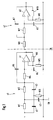
- FIG. 1 is a circuit diagram of an embodiment of an active low-pass filter tp shown by means of Resistors, capacitors and operational amplifiers is realized. As if by the vertical dashed line is indicated, the low-pass filter tp is from a first and together from a second filter subcircuit s1 s2 set.
- the filter subcircuit s1 is on the input side with a AC signal to be filtered is fed and contains on the input side a first series connection from a first Resistor W1 with a resistance value R1 and from one second resistor W2 with a resistance value R2, the is approximately equal to the resistance value R1.
- one of the first ones is in the filter subcircuit s1 Series connection second series connection connected in parallel from a first capacitor K1 with a capacitance C1 and a second capacitor K2 with a capacitance C2 which is approximately equal to the capacitance C1.
- s1 connects in the filter subcircuit third capacitor K3 with a capacitance C3 the first and the second resistor W1, W2, namely their common connection point, with a circuit zero SN and a third resistor W3 with a resistance value R3 connects the first and the second capacitor K1, K2, namely their common connection point with which Circuit zero point SN.
- the capacity C3 is at least five times the capacity C1, and the Resistance value R3 is large compared to half Resistance value R1 and large compared to half Resistance value R2.
- the components of the filter subcircuit s1 explained so far form a passive double-T filter, but only when considered individually and in terms of structure, the dimensions of which, however, deviate completely from the above-mentioned dimensioning according to the prior art.
- the invention prescribes: R1 ⁇ R2; R3 >>0.5R1; C1 ⁇ C2; C3> 5C1.
- a fourth is in the filter subcircuit s1 Resistor W4 with a resistance value R4 which is approximately is equal to the resistance value R3, and a fourth Capacitor K4 with a capacitance C4 available is approximately equal to the capacitance C1.
- the filter subcircuit s1 has a fifth Capacitor K5 with a capacitance C5, a fifth Resistor W5 with a resistance value R5, a sixth Resistor W6 with a resistance value (k-1) R5 and one first operational amplifier o1; here k is the Voltage amplification of the operational amplifier ol.
- the Capacitance C5 depends on k: the larger k is, the smaller can be C5.
- An output of the operational amplifier o1 is above Capacitor K5 across resistor W2 and capacitor K2, namely at their common connection point.
- a non-inverting Input of the operational amplifier o1 is via resistor W4 on resistor W2, on capacitor K2 and at the capacitor K5, namely at the connection point of this the latter three components, as well as the fourth Capacitor K4 at circuit zero SN.
- the output of the operational amplifier o1 is a second Filter subcircuit s2 downstream, which is a Sallen key low pass with a second operational amplifier o2.
- In 1 contains a third Sallen Key low pass Series connection of a seventh resistor W7 with a Resistance value R7 and an eighth resistor W8 with a resistance value R8.
- capacitor K6 with one Capacitance C6 and a seventh capacitor K7 with a Capacity C7.
- the capacitance C7 depends on k ': the larger k 'is, the smaller C7 can be.
- the components W7, W8, W9, W10, C6, C7 are with the second operational amplifier o2 connected as follows: a The output of the operational amplifier is above the Capacitor K7 across resistor W7 and across resistor W8, namely at their connection point, and the exit gives that filtered alternating signal.
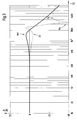
- the amplitude profile A shown in FIG Transfer function of the first filter subcircuit s1 shows a constant between 10 Hz and about 200 Hz Course with the value 0 dB and then starts up to about 1600 Hz to drop to an intermediate minimum Zn of about -2 dB.
- a maximum Mx of about +2 dB a maximum frequency fx of about 2300 Hz and then falls very steep at first to 0 dB at about 2400 Hz and then up a minimum Mn of about -50 dB at a minimum frequency fn from about 3300 Hz.
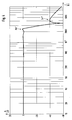
- the amplitude profile A of is also dotted in FIG 2 drawn in and there are the intermediate minimum Zn, the maximum Mx and the minimum Mn of this curve again marked.
- the intermediate maximum Zx of FIG. 2 is one Intermediate maximum Zx "of about -40 dB, compared to what the intermediate maximum Zx of FIG. 2 a decrease of approximately 18 dB means.
- the slope S between the maximum Mx " and the minimum Mn " is approximately equal to the corresponding one 2 and is thus again about -340 dB / power of ten.
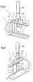
- 5 to 7 is a preferred use of the Low pass filter of the invention is shown, namely this is a partial circuit of an evaluation electronics for a vortex flow sensor 1 of a vortex flow meter; for a better understanding is first 5 and 6, the structure of the vortex flowmeter explained in more detail.
- FIGS. 5 and 6 and the overview show serving perspective views, on the one hand in Flow direction seen (Fig. 5) and on the other hand against seen the direction of flow (Fig. 6), the partial cut vortex flow sensor 1 with a a tube wall 21 of a measuring tube 2 fixed and by a vortex sensor 3 protruding therethrough Vortex flowmeter 1 works with evaluation electronics together, whose block diagram is shown in Fig. 7 is shown, so the vortex flow meter mentioned arises.
- a dynamic is preferably used as the vortex sensor 3 compensated vortex sensor with a capacitive Sensor element as described in US-A 60 03 384 whose content is part of the disclosure of this application.
- a bluff body 4 is arranged inside, which is connected to the measuring tube 2 to form a first fixing point 41 shown and a hidden second fixing point 41 * connected is.
- the center of bore 22 and the center the fixing point 41 lie on a surface line of the Measuring tube 2.
- the bluff body 4 has an impact surface 42 against which the Operation of a fluid to be measured, e.g. a liquid, a Gas or a steam.
- the bluff body 4 also has two side surfaces, of which only one (front) Side surface 43 can be seen in FIGS. 5 and 6.
- Of the Baffle 42 and the side surfaces become two Tear-off edges formed, of which only one (front) Tear-off edge 44 completely and a (rear) tear-off edge 45 are indicated in Fig. 1.
- the bluff body 4 of FIGS. 5 and 6 has essentially the shape of a straight triangle column, i.e. a column with one triangular cross section. However, others can Usual forms of the bluff body are used.
- a Kármán'sche forms downstream of the bluff body 4 Vortex street in the fluid characterized by that at everyone Alternately tear off the tear-off edge and swirl from the flowing Fluid to be taken along. These vortices create local ones Pressure fluctuations in the fluid, their time-related demolition frequency, so their so-called vortex frequency, a measure for the flow rate and / or the Volume flow of the fluid is.
- the volume flow is by definition that per unit of time by each Cross-sectional area of the measuring tube flowing volume of Fluid.
- the pressure fluctuations are measured by means of the vortex sensor 3 in at least one representative of the pressure fluctuations Vortex signal transformed that of the evaluation electronics mentioned which is fed the flow rate and / or the volume flow of the fluid in the usual way calculated.
- the vortex sensor 3 is downstream of the bluff body 4 in the Bore 22 of the tube wall 21 of the measuring tube 2 used and seals the bore 22 to the outer surface of the measuring tube 2 from what the vortex sensor 3 is screwed to the tube wall 21 is.
- the sensor flag 31 has main surfaces, of which in the Fig. 5 and 6 only the main surface 311 can be seen.
- the Main surfaces are aligned with the surface line mentioned Measuring tube 2 and form a front edge.
- the sensor flag 31 can also have other suitable spatial forms; so she can e.g. have two parallel major surfaces, the two form parallel front edges.
- the sensor flag 31 is shorter than the diameter of the measuring tube 2 and is rigid.
- Vortex sensor instead of the vortex sensor in the tube wall of the measuring tube is inserted and it has the sensor flag, the Vortex sensor arranged in a bore of the bluff body and is then instead of with the Senor flag with a rigid cylindrical probe.
- Fig. 7 shown evaluation electronics usually a Filter circuit that has a high pass and a low pass includes.
- the evaluation electronics of FIG. 7 use the active low-pass filter of the invention.
- the vortex sensor 3 is included in the block diagram of FIG. 7 coupled to the input of a high pass hp.
- An amplifier vk is indicated by dashed lines between an output of the Swirl sensor 3 and an input of the high pass hp can be inserted so that the vortex sensor 3 emitted b vortex signal is sufficiently amplified before it comes to the high pass hp.
- the high-pass hp is the active low-pass filter tp downstream, that from the above explained in detail Filter subcircuits s1, s2 exists.
- the low pass filter tp is a Schmitt trigger st downstream, which consists of the signal occurring at the output of the low-pass filter tp, the i.a. is a sine signal, generates a square wave signal.
- the Schmitt trigger st is a counter z and this a display unit dp and / or an ammeter mi downstream.
Landscapes
- Networks Using Active Elements (AREA)
Abstract
Description
S = -20n dB/Frequenz-Zehnerpotenz (dB = Dezibel).
- eine Eingangs-Serienschaltung aus einem eingangs-seitigen Widerstand mit einem Widerstandswert r1 und aus einem eingangs-abgewandten Widerstand mit einem Widerstandswert r2,
- einen Operationsverstärker, von dem
- ein nicht-invertierender Eingang an der Serienschaltung und über einen Kondensator mit einer Kapazität c1 am Schaltungsnullpunkt liegt,
- ein invertierender Eingang über einen Widerstand mit einem Widerstandswert r am Schaltungsnullpunkt und über einen Widerstand mit einem Widerstandswert (α-1)r an einem Ausgang des Operationsverstärkers liegt, und
- der Ausgang über einen Kondensator mit einer Kapazität c2 am eingangs-seitigen Widerstand und am eingangs-abgewandten Widerstand liegt,
- wobei mit α die Spannungsverstärkung des Operationsverstärkers bezeichnet ist.
- eine erste Serienschaltung aus einem eingangs-seitigen Widerstand mit einem Widerstandswert R1 und aus einem ausgangs-seitigen Widerstand mit einem Widerstandswert R2, der gleich dem Widerstandswert R1 ist,
- eine der ersten Serienschaltung parallelgeschaltete zweite Serienschaltung aus einem eingangs-seitigen Kondensator mit einer Kapazität C1 und aus einem ausgangs-seitigen Kondensator mit einer Kapazität C2, die gleich der ersten Kapazität C1 ist,
- einen den ersten und den zweiten Widerstand mit einem Schaltungsnullpunkt verbindenden dritten Kondensator mit einer Kapazität C3, die doppelt so groß wie die Kapazität C1 ist, und
- einen den ersten und den zweiten Kondensator mit dem Schaltungsnullpunkt verbindenden dritten Widerstand mit einem Widerstandswert R3, der halb so groß wie der Widerstandswert R1 ist.
- eine mit einem zu filternden Wechselsignal gespeiste
erste Filter-Teilschaltung, die enthält:
- eingangsseitig eine erste Serienschaltung aus einem ersten Widerstand mit einem Widerstandswert R1 und aus einem zweiten Widerstand mit einem Widerstandswert R2, der ungefähr gleich dem Widerstandswert R1 ist,
- eine der ersten Serienschaltung parallelgeschaltete zweite Serienschaltung aus einem ersten Kondensator mit einer Kapazität C1 und einem zweiten Kondensator mit einer Kapazität C2, die ungefähr gleich der Kapazität C1 ist,
- einen den ersten und den zweiten Widerstand mit einem Schaltungsnullpunkt verbindenden dritten Kondensator mit einer Kapazität C3, die mindestens fünfmal so groß wie die Kapazität C1 ist,
- einen den ersten und den zweiten Kondensator mit dem Schaltungsnullpunkt verbindenden dritten Widerstand mit einem Widerstandswert R3, der groß gegenüber dem halben Widerstandswert R1 und groß gegenüber dem halben Widerstandswert R2 ist,
- einen vierten Widerstand mit einem Widerstandswert R4, der ungefähr gleich dem Widerstandswert R3 ist,
- einen vierten Kondensator mit einer Kapazität C4, die ungefähr gleich der Kapazität C1 ist,
- einen fünften Kondensator mit einer Kapazität C5,
- einen fünften Widerstand mit einem Widerstandswert R5,
- einen sechsten Widerstand mit einem Widerstandswert (k-1)R5,
- einen ersten Operationsverstärker, von dem
- ein Ausgang über den fünften Kondensator am zweiten Widerstand und am zweiten Kondensator liegt,
- ein nicht-invertierender Eingang über den vierten Widerstand am zweiten Widerstand, am zweiten Kondensator und am fünften Kondensator sowie über den vierten Kondensator am Schaltungsnullpunkt liegt und
- ein invertierender Eingang über den fünften Widerstand am Schaltungsnullpunkt sowie über den sechsten Widerstand am Ausgang liegt,
- wobei mit k die Spannungsverstärkung des ersten Operationsverstärkers bezeichnet ist, und
- eine dem Ausgang des ersten Operationsverstärkers nachgeschaltete zweite Filter-Teilschaltung in Form eines Sallen-Key-Tiefpasses mit einem zweiten Operationsverstärker.
- eine dritte Serienschaltung aus einem siebten Widerstand mit einem Widerstandswert R7 und aus einem achten Widerstand mit einem Widerstandswert R8,
- einen neunten Widerstand mit einem Widerstandswert R9,
- einen zehnten Widerstand mit einem Widerstandswert (k'-1)R9,
- einen sechsten Kondensator mit einer Kapazität C6,
- einen siebten Kondensator mit einer Kapazität C7 und
- den zweiten Operationsverstärker, von dem
- ein Ausgang über den siebten Kondensator am siebten Widerstand sowie am achten Widerstand liegt und das gefilterte Wechselsignal abgibt,
- ein nicht-invertierender Eingang über die dritte Serienschaltung am Ausgang des ersten Operationsverstärkers sowie über den sechsten Kondensator am Schaltungsnullpunkt liegt und
- ein invertierender Eingang über den neunten Widerstand am Schaltungsnullpunkt sowie über den zehnten Widerstand am Ausgang liegt,
- wobei mit k' die Spannungsverstärkung des zweiten Operationsverstärkers bezeichnet ist.
- in dem ein Staukörper angeordnet ist, der
- der Erzeugung Kármán'scher Wirbel im strömenden Fluid dient und
- an mindestens einer Fixierstelle mit der Rohrwand des Messrohrs von innen verbunden ist, und
- in dem ein auf von den Wirbeln erzeugte Druckschwankungen
ansprechender und mindestens ein die Druckschwankungen
repräsentierendes Wirbelsignal abgebender Wirbelsensor
- entweder stromabwärts vom Staukörper in eine Bohrung der Rohrwand des Messrohrs eingesetzt ist und diese Bohrung abdichtet,
- oder in einer Bohrung des Staukörpers angeordnet ist,
- einen dem Wirbelsensor nachgeschalteten Hochpass,
- das dem Hochpass nachgeschaltete aktive Tiefpassfilter,
- einen dem Tiefpassfilter nachgeschalteten Schmitt-Trigger,
- einen dem Schmitt-Trigger nachgeschalteten Zähler und
- eine dem Zähler nachgeschaltete Anzeige-Einheit.
- Fig. 1
- zeigt ein Schaltbild eines Ausführungsbeispiels des aktiven Tiefpassfilters,
- Fig. 2
- zeigt ein logarithmisches Frequenz-Diagramm des Amplitudenverlaufs der Übertragungsfunktion der ersten Filter-Teilschaltung von Fig. 1,
- Fig. 3
- zeigt ein logarithmisches Frequenz-Diagramm des Amplitudenverlaufs der Übertragungsfunktion der zweiten Filter-Teilschaltung (Sallen-Key-Tiefpass) von Fig. 1,
- Fig. 4
- zeigt ein logarithmisches Frequenz-Diagramm des Amplitudenverlaufs der Übertragungsfunktion des aktiven Tiefpassfilters von Fig. 1,
- Fig. 5
- zeigt in Strömungsrichtung gesehen perspektivisch und teilweise aufgeschnitten einen Wirbelströmungsaufnehmer,
- Fig. 6
- zeigt gegen die Strömungsrichtung gesehen perspektivisch und teilweise aufgeschnitten den Wirbelströmungsaufnehmer von Fig. 5, und
- Fig. 7
- zeigt ein Blockschaltbild einer mit dem aktiven Tiefpassfilter der Fig. 1 bestückten Auswerte-Elektronik eines Wirbeldurchflussmessers.
R1 = R2; R3 = 0,5R1; C1 = C2; C3 = 2C1.
Demgegenüber schreibt die Erfindung vor:
R1 ≈ R2; R3 >> 0,5R1; C1 ≈ C2; C3 > 5C1.
- C1 = 1 nF; C2 = 1 nF; C3 = 10 nF; C4 = 1 nF;
- C5 = 10 nF; C6 = 1 nF; C7 = 10 nF.
- einen Verstärker für mindestens ein Wirbelsignal,
- einen dem Verstärker nachgeschalteten Butterworth-Hochpass zweiter Ordnung,
- einen dem Butterworth-Hochpass nachgeschalteten Tschebyscheff-Tiefpass zweiter Ordnung,
- einen dem Tschebyscheff-Tiefpass nachgeschalteten Schmitt-Trigger,
- einen dem Schmitt-Trigger nachgeschalteten Zähler und
- eine dem Zähler nachgeschaltete Anzeige-Einheit.
- einen Bandpass oder
- einen Bandpass, dem ein Tiefpass parallelgeschaltet ist,
- einen dem Bandpass nachgeschalteten Effektivwert-Gleichrichter und
- eine dem Effektivwert-Gleichrichter nachgeschaltete
Anzeige-Einheit,
- wobei der Bandpass aus einem Hochpassteil und einem Tiefpassteil besteht und
- wobei eine durch eine erste Sallen-Key-Schaltung eingestellte untere Bandgrenze eine Steigung von -12 dB/Frequenzoktave und eine durch eine zweite Sallen-Key-Schaltung eingestellte obere Bandgrenze eine Steigung von -12 dB/Frequenzoktave aufweist.
- 12 dB/Frequenzoktave = -20 dB/Frequenz-Zehnerpotenz.
Die Auswerte-Elektronik von Fig. 7 verwendet demgegenüber das aktive Tiefpassfilter der Erfindung.
Claims (4)
- Aktives Tiefpassfilter (tp), das mittels Widerständen, Kondensatoren und Operationsverstärkern realisiert ist und das umfasst:eine mit einem zu filternden Wechselsignal gespeiste erste Filter-Teilschaltung (s1), die enthält:eingangsseitig eine erste Serienschaltung aus einem ersten Widerstand (W1) mit einem Widerstandswert R1 und aus einem zweiten Widerstand (W2) mit einem Widerstandswert R2, der ungefähr gleich dem Widerstandswert R1 ist,eine der ersten Serienschaltung parallelgeschaltete zweite Serienschaltung aus einem ersten Kondensator (K1) mit einer Kapazität C1 und einem zweiten Kondensator (K2) mit einer Kapazität C2, die ungefähr gleich der Kapazität C1 ist,einen den ersten und den zweiten Widerstand (W1, W2) mit einem Schaltungsnullpunkt (SN) verbindenden dritten Kondensator (K3) mit einer Kapazität C3, die mindestens fünfmal so groß wie die Kapazität C1 ist,einen den ersten und den zweiten Kondensator (K1, K2) mit dem Schaltungsnullpunkt (SN) verbindenden dritten Widerstand (W3) mit einem Widerstandswert R3, der groß gegenüber dem halben Widerstandswert R1 und groß gegenüber dem halben Widerstandswert R2 ist,einen vierten Widerstand (W4) mit einem Widerstandswert R4, der ungefähr gleich dem Widerstandswert R3 ist,einen vierten Kondensator (K4) mit einer Kapazität C4, die ungefähr gleich der Kapazität C1 ist,einen fünften Kondensator (K5) mit einer Kapazität C5,einen fünften Widerstand (W5) mit einem Widerstandswert R5,einen sechsten Widerstand (W6) mit einem Widerstandswert (k-1)R5,einen ersten Operationsverstärker (o1), von demein Ausgang über den fünften Kondensator (K5) am zweiten Widerstand (W2) und am zweiten Kondensator (K2) liegt,ein nicht-invertierender Eingang über den vierten Widerstand (W4) am zweiten Widerstand (W2), am zweiten Kondensator (K2) und am fünften Kondensator (K5) sowie über den vierten Kondensator (K4) am Schaltungsnullpunkt (SN) liegt undein invertierender Eingang über den fünften Widerstand (W5) am Schaltungsnullpunkt (SN) sowie über den sechsten Widerstand (W6) am Ausgang liegt,wobei mit k die Spannungsverstärkung des ersten Operationsverstärkers (o1) bezeichnet ist, undeine dem Ausgang des ersten Operationsverstärkers (o1) nachgeschaltete zweite Filter-Teilschaltung (s2) in Form eines Sallen-Key-Tiefpasses mit einem zweiten Operationsverstärker (o2).
- Aktives Tiefpassfilter nach Anspruch 1, bei dem der Sallen-Key-Tiefpass umfasst:eine dritte Serienschaltung aus einem siebten Widerstand (W7) mit einem Widerstandswert R7 und aus einem achten Widerstand (W8) mit einem Widerstandswert R8,einen neunten Widerstand (W9) mit einem Widerstandswert R9,einen zehnten Widerstand (W10) mit einem Widerstandswert (k'-1)R9,einen sechsten Kondensator (K6), mit einer Kapazität C6,einen siebten Kondensator (K7) mit einer Kapazität C7 undden zweiten Operationsverstärker (o2), von demein Ausgang über den siebten Kondensator (K7) am siebten Widerstand (W7) sowie am achten Widerstand (W8) liegt und das gefilterte Wechselsignal abgibt,ein nicht-invertierender Eingang über die dritte Serienschaltung am Ausgang des ersten Operationsverstärkers (o1) sowie über den sechsten Kondensator (K6) am Schaltungsnullpunkt liegt undein invertierender Eingang über den neunten Widerstand (W9) am Schaltungsnullpunkt (SN) sowie über den zehnten Widerstand (W10) am Ausgang liegt,wobei mit k' die Spannungsverstärkung des zweiten Operationsverstärkers (o2) bezeichnet ist.
- Verwendung eines aktiven Tiefpassfilters nach Anspruch 1 oder 2 in einer Auswerte-Elektronik für einen Wirbel-Durchflussmesser, von dem ein Wirbel-Durchflussaufnehmer (1) ein eine Rohrwand (21) aufweisendes und von einem zu messenden Fluid durchströmbares Messrohr (2) umfasst,welche Auswerte-Elektronik umfasst:in dem ein Staukörper (4) angeordnet ist, derder Erzeugung Kármán'scher Wirbel im strömenden Fluid dient undan mindestens einer Fixierstelle (41, 41*) mit der Rohrwand des Messrohrs von innen verbunden ist, undin dem ein auf von den Wirbeln erzeugte Druckschwankungen ansprechender und mindestens ein die Druckschwankungen repräsentierendes Wirbelsignal abgebender Wirbelsensor (3)entweder stromabwärts vom Staukörper in eine Bohrung (22) der Rohrwand des Messrohrs eingesetzt ist und diese Bohrung abdichtet,oder in einer Bohrung des Staukörpers angeordnet ist,einen dem Wirbelsensor (3) nachgeschalteten Hochpass (hp),das dem Hochpass (hp) nachgeschaltete aktive Tiefpassfilter (tp),einen dem Tiefpassfilter nachgeschalteten Schmitt-Trigger (st),einen dem Schmitt-Trigger (st) nachgeschalteten Zähler (z) undeine dem Zähler nachgeschaltete Anzeige-Einheit (dp).
- Auswerte-Elektronik nach Anspruch 3, bei der der Hochpass (hp) ein Tschebyscheff-Filter zweiter Ordnung mit 0,5 dB Überschwingen ist.
Priority Applications (3)
| Application Number | Priority Date | Filing Date | Title |
|---|---|---|---|
| EP01122322A EP1294091B1 (de) | 2001-09-18 | 2001-09-18 | Aktives Tiefpassfilter |
| AT01122322T ATE382986T1 (de) | 2001-09-18 | 2001-09-18 | Aktives tiefpassfilter |
| DE50113443T DE50113443D1 (de) | 2001-09-18 | 2001-09-18 | Aktives Tiefpassfilter |
Applications Claiming Priority (1)
| Application Number | Priority Date | Filing Date | Title |
|---|---|---|---|
| EP01122322A EP1294091B1 (de) | 2001-09-18 | 2001-09-18 | Aktives Tiefpassfilter |
Publications (2)
| Publication Number | Publication Date |
|---|---|
| EP1294091A1 true EP1294091A1 (de) | 2003-03-19 |
| EP1294091B1 EP1294091B1 (de) | 2008-01-02 |
Family
ID=8178658
Family Applications (1)
| Application Number | Title | Priority Date | Filing Date |
|---|---|---|---|
| EP01122322A Expired - Lifetime EP1294091B1 (de) | 2001-09-18 | 2001-09-18 | Aktives Tiefpassfilter |
Country Status (3)
| Country | Link |
|---|---|
| EP (1) | EP1294091B1 (de) |
| AT (1) | ATE382986T1 (de) |
| DE (1) | DE50113443D1 (de) |
Cited By (3)
| Publication number | Priority date | Publication date | Assignee | Title |
|---|---|---|---|---|
| EP1774738A4 (de) * | 2004-07-19 | 2008-04-09 | Aerielle Inc | Verbesserter rc-filterpol für fm-sender |
| CN103941279A (zh) * | 2014-05-08 | 2014-07-23 | 东华理工大学 | 基于脉宽和幅度双参数的核脉冲信号数字高斯成形方法 |
| CN116864280A (zh) * | 2023-07-04 | 2023-10-10 | 北京智芯微电子科技有限公司 | 电流互感器、回路状态巡检仪以及能源控制器 |
Citations (2)
| Publication number | Priority date | Publication date | Assignee | Title |
|---|---|---|---|---|
| US2623947A (en) * | 1947-09-29 | 1952-12-30 | Standard Oil Dev Co | Phase correction filter circuit |
| US5576497A (en) * | 1995-05-09 | 1996-11-19 | The Foxboro Company | Adaptive filtering for a vortex flowmeter |
-
2001
- 2001-09-18 DE DE50113443T patent/DE50113443D1/de not_active Expired - Fee Related
- 2001-09-18 EP EP01122322A patent/EP1294091B1/de not_active Expired - Lifetime
- 2001-09-18 AT AT01122322T patent/ATE382986T1/de not_active IP Right Cessation
Patent Citations (2)
| Publication number | Priority date | Publication date | Assignee | Title |
|---|---|---|---|---|
| US2623947A (en) * | 1947-09-29 | 1952-12-30 | Standard Oil Dev Co | Phase correction filter circuit |
| US5576497A (en) * | 1995-05-09 | 1996-11-19 | The Foxboro Company | Adaptive filtering for a vortex flowmeter |
Non-Patent Citations (1)
| Title |
|---|
| H.J.KOWALSKI: "VEREINFACHTE DIMENSIONIERUNG AKTIVER RC-SCHALTUNGEN", RADIO FERNSEHEN ELEKTRONIK., vol. 35, no. 2, 1986, VEB VERLAG TECHNIK. BERLIN., DE, XP002188463, ISSN: 1436-1574 * |
Cited By (3)
| Publication number | Priority date | Publication date | Assignee | Title |
|---|---|---|---|---|
| EP1774738A4 (de) * | 2004-07-19 | 2008-04-09 | Aerielle Inc | Verbesserter rc-filterpol für fm-sender |
| CN103941279A (zh) * | 2014-05-08 | 2014-07-23 | 东华理工大学 | 基于脉宽和幅度双参数的核脉冲信号数字高斯成形方法 |
| CN116864280A (zh) * | 2023-07-04 | 2023-10-10 | 北京智芯微电子科技有限公司 | 电流互感器、回路状态巡检仪以及能源控制器 |
Also Published As
| Publication number | Publication date |
|---|---|
| EP1294091B1 (de) | 2008-01-02 |
| DE50113443D1 (de) | 2008-02-14 |
| ATE382986T1 (de) | 2008-01-15 |
Similar Documents
| Publication | Publication Date | Title |
|---|---|---|
| DE68922139T2 (de) | Symmetrische Integratorfilterschaltungen. | |
| EP0029485A1 (de) | Einrichtung zur kapazitiven Füllstandsmessung | |
| DE2813946B1 (de) | Filterschaltung mit einer biquadratischen UEbertragungsfunktion | |
| DE2113236B2 (de) | Schaltungsanordnung zum Ermitteln der Neigungspolarität | |
| DE60215827T2 (de) | Impedanzmessschaltung und kapazitätsmessschaltung | |
| DE102018109914A1 (de) | EMV robuste mikroelektronisch integrierbare Messschaltung für Kapazitätswerte einer unbekannten Kapazität | |
| EP1030168A1 (de) | Signalverabeitungsschaltung für eine Differenzspannung, insbesondere für ein magnetisch-induktives Durchflussmessgerät | |
| DE4018016A1 (de) | Hitzdraht-luftmengenmesser | |
| DE69223318T2 (de) | RC-Filter für niedrige und sehr niedrige Frequenzanwendungen | |
| EP1294091B1 (de) | Aktives Tiefpassfilter | |
| DE69014831T2 (de) | Schaltung zur Quotientenmessung mit verbesserter Rauschunterdrückung. | |
| DE2603185A1 (de) | Anordnung zur kapazitiven messung des fuellstands eines behaelters | |
| EP0073293A2 (de) | Vierpol | |
| DE3752174T2 (de) | Netzwerk mit signalformung | |
| DE3686423T2 (de) | Allpasskreis zweiter ordnung. | |
| DE19701067B4 (de) | Verfahren und Schaltungsanordnung zur Frequenzvervielfachung | |
| DE102020113558B4 (de) | Lock-In-Verstärker mit optimaler Rauschunterdrückung | |
| DE1230088C2 (de) | Anordnung zum umsetzen einer messspannung zum ermitteln der frequenzabhaengigen daempfung von fernmeldeleitungen | |
| DE2808581C2 (de) | Filterschaltung mit einer Bandpaß- Übertragungsfunktion vierten Grades | |
| DE1766461C3 (de) | Aktive RC-Schaltung mit biquadratischer Charakteristik | |
| DE3421645C2 (de) | Hochpaß- bzw Tiefpaßfilter | |
| DE3345718C2 (de) | ||
| DE2238763C3 (de) | Verfahren zur Effektivwertmessung mit Signalrückführung | |
| DE2851904C2 (de) | ||
| DE1516174C (de) | Frequenzmeßvorrichtung |
Legal Events
| Date | Code | Title | Description |
|---|---|---|---|
| PUAI | Public reference made under article 153(3) epc to a published international application that has entered the european phase |
Free format text: ORIGINAL CODE: 0009012 |
|
| AK | Designated contracting states |
Designated state(s): AT BE CH CY DE DK ES FI FR GB GR IE IT LI LU MC NL PT SE TR Kind code of ref document: A1 Designated state(s): AT BE CH CY DE DK ES FI FR GB GR IE IT LI LU MC NL PT SE TR |
|
| AX | Request for extension of the european patent |
Extension state: AL LT LV MK RO SI |
|
| 17P | Request for examination filed |
Effective date: 20030818 |
|
| AKX | Designation fees paid |
Designated state(s): AT BE CH CY DE DK ES FI FR GB GR IE IT LI LU MC NL PT SE TR |
|
| 17Q | First examination report despatched |
Effective date: 20061221 |
|
| RTI1 | Title (correction) |
Free format text: ACTIVE LOWPASS FILTER |
|
| GRAP | Despatch of communication of intention to grant a patent |
Free format text: ORIGINAL CODE: EPIDOSNIGR1 |
|
| RIN1 | Information on inventor provided before grant (corrected) |
Inventor name: SIMON, ANTOINE Inventor name: RINGIER, ROBERT |
|
| GRAS | Grant fee paid |
Free format text: ORIGINAL CODE: EPIDOSNIGR3 |
|
| GRAA | (expected) grant |
Free format text: ORIGINAL CODE: 0009210 |
|
| AK | Designated contracting states |
Kind code of ref document: B1 Designated state(s): AT BE CH CY DE DK ES FI FR GB GR IE IT LI LU MC NL PT SE TR |
|
| REG | Reference to a national code |
Ref country code: GB Ref legal event code: FG4D Free format text: NOT ENGLISH |
|
| REG | Reference to a national code |
Ref country code: IE Ref legal event code: FG4D Free format text: LANGUAGE OF EP DOCUMENT: GERMAN |
|
| REG | Reference to a national code |
Ref country code: CH Ref legal event code: EP |
|
| REF | Corresponds to: |
Ref document number: 50113443 Country of ref document: DE Date of ref document: 20080214 Kind code of ref document: P |
|
| GBT | Gb: translation of ep patent filed (gb section 77(6)(a)/1977) |
Effective date: 20080501 |
|
| PG25 | Lapsed in a contracting state [announced via postgrant information from national office to epo] |
Ref country code: FI Free format text: LAPSE BECAUSE OF FAILURE TO SUBMIT A TRANSLATION OF THE DESCRIPTION OR TO PAY THE FEE WITHIN THE PRESCRIBED TIME-LIMIT Effective date: 20080102 Ref country code: ES Free format text: LAPSE BECAUSE OF FAILURE TO SUBMIT A TRANSLATION OF THE DESCRIPTION OR TO PAY THE FEE WITHIN THE PRESCRIBED TIME-LIMIT Effective date: 20080413 |
|
| ET | Fr: translation filed | ||
| PG25 | Lapsed in a contracting state [announced via postgrant information from national office to epo] |
Ref country code: PT Free format text: LAPSE BECAUSE OF FAILURE TO SUBMIT A TRANSLATION OF THE DESCRIPTION OR TO PAY THE FEE WITHIN THE PRESCRIBED TIME-LIMIT Effective date: 20080602 |
|
| REG | Reference to a national code |
Ref country code: IE Ref legal event code: FD4D |
|
| PG25 | Lapsed in a contracting state [announced via postgrant information from national office to epo] |
Ref country code: DK Free format text: LAPSE BECAUSE OF FAILURE TO SUBMIT A TRANSLATION OF THE DESCRIPTION OR TO PAY THE FEE WITHIN THE PRESCRIBED TIME-LIMIT Effective date: 20080102 Ref country code: IE Free format text: LAPSE BECAUSE OF FAILURE TO SUBMIT A TRANSLATION OF THE DESCRIPTION OR TO PAY THE FEE WITHIN THE PRESCRIBED TIME-LIMIT Effective date: 20080102 Ref country code: SE Free format text: LAPSE BECAUSE OF FAILURE TO SUBMIT A TRANSLATION OF THE DESCRIPTION OR TO PAY THE FEE WITHIN THE PRESCRIBED TIME-LIMIT Effective date: 20080402 |
|
| PLBE | No opposition filed within time limit |
Free format text: ORIGINAL CODE: 0009261 |
|
| STAA | Information on the status of an ep patent application or granted ep patent |
Free format text: STATUS: NO OPPOSITION FILED WITHIN TIME LIMIT |
|
| PGFP | Annual fee paid to national office [announced via postgrant information from national office to epo] |
Ref country code: FR Payment date: 20080912 Year of fee payment: 8 Ref country code: NL Payment date: 20080915 Year of fee payment: 8 |
|
| 26N | No opposition filed |
Effective date: 20081003 |
|
| PGFP | Annual fee paid to national office [announced via postgrant information from national office to epo] |
Ref country code: GB Payment date: 20080918 Year of fee payment: 8 |
|
| PGFP | Annual fee paid to national office [announced via postgrant information from national office to epo] |
Ref country code: DE Payment date: 20080919 Year of fee payment: 8 |
|
| BERE | Be: lapsed |
Owner name: ENDRESS + HAUSER FLOWTEC A.G. Effective date: 20080930 |
|
| PG25 | Lapsed in a contracting state [announced via postgrant information from national office to epo] |
Ref country code: MC Free format text: LAPSE BECAUSE OF NON-PAYMENT OF DUE FEES Effective date: 20080930 |
|
| REG | Reference to a national code |
Ref country code: CH Ref legal event code: PL |
|
| PG25 | Lapsed in a contracting state [announced via postgrant information from national office to epo] |
Ref country code: CY Free format text: LAPSE BECAUSE OF FAILURE TO SUBMIT A TRANSLATION OF THE DESCRIPTION OR TO PAY THE FEE WITHIN THE PRESCRIBED TIME-LIMIT Effective date: 20080102 Ref country code: BE Free format text: LAPSE BECAUSE OF NON-PAYMENT OF DUE FEES Effective date: 20080930 |
|
| PG25 | Lapsed in a contracting state [announced via postgrant information from national office to epo] |
Ref country code: IT Free format text: LAPSE BECAUSE OF FAILURE TO SUBMIT A TRANSLATION OF THE DESCRIPTION OR TO PAY THE FEE WITHIN THE PRESCRIBED TIME-LIMIT Effective date: 20080102 |
|
| PG25 | Lapsed in a contracting state [announced via postgrant information from national office to epo] |
Ref country code: LI Free format text: LAPSE BECAUSE OF NON-PAYMENT OF DUE FEES Effective date: 20080930 Ref country code: AT Free format text: LAPSE BECAUSE OF NON-PAYMENT OF DUE FEES Effective date: 20080918 Ref country code: CH Free format text: LAPSE BECAUSE OF NON-PAYMENT OF DUE FEES Effective date: 20080930 |
|
| REG | Reference to a national code |
Ref country code: NL Ref legal event code: V1 Effective date: 20100401 |
|
| GBPC | Gb: european patent ceased through non-payment of renewal fee |
Effective date: 20090918 |
|
| REG | Reference to a national code |
Ref country code: FR Ref legal event code: ST Effective date: 20100531 |
|
| PG25 | Lapsed in a contracting state [announced via postgrant information from national office to epo] |
Ref country code: NL Free format text: LAPSE BECAUSE OF NON-PAYMENT OF DUE FEES Effective date: 20100401 Ref country code: LU Free format text: LAPSE BECAUSE OF NON-PAYMENT OF DUE FEES Effective date: 20080918 Ref country code: FR Free format text: LAPSE BECAUSE OF NON-PAYMENT OF DUE FEES Effective date: 20090930 Ref country code: DE Free format text: LAPSE BECAUSE OF NON-PAYMENT OF DUE FEES Effective date: 20100401 |
|
| PG25 | Lapsed in a contracting state [announced via postgrant information from national office to epo] |
Ref country code: TR Free format text: LAPSE BECAUSE OF FAILURE TO SUBMIT A TRANSLATION OF THE DESCRIPTION OR TO PAY THE FEE WITHIN THE PRESCRIBED TIME-LIMIT Effective date: 20080102 |
|
| PG25 | Lapsed in a contracting state [announced via postgrant information from national office to epo] |
Ref country code: GR Free format text: LAPSE BECAUSE OF FAILURE TO SUBMIT A TRANSLATION OF THE DESCRIPTION OR TO PAY THE FEE WITHIN THE PRESCRIBED TIME-LIMIT Effective date: 20080403 |
|
| PG25 | Lapsed in a contracting state [announced via postgrant information from national office to epo] |
Ref country code: GB Free format text: LAPSE BECAUSE OF NON-PAYMENT OF DUE FEES Effective date: 20090918 |