EP1292768B1 - Axialkolbenmaschine - Google Patents
Axialkolbenmaschine Download PDFInfo
- Publication number
- EP1292768B1 EP1292768B1 EP01925467A EP01925467A EP1292768B1 EP 1292768 B1 EP1292768 B1 EP 1292768B1 EP 01925467 A EP01925467 A EP 01925467A EP 01925467 A EP01925467 A EP 01925467A EP 1292768 B1 EP1292768 B1 EP 1292768B1
- Authority
- EP
- European Patent Office
- Prior art keywords
- axial piston
- housing
- piston engine
- drive shaft
- transport elements
- Prior art date
- Legal status (The legal status is an assumption and is not a legal conclusion. Google has not performed a legal analysis and makes no representation as to the accuracy of the status listed.)
- Expired - Lifetime
Links
- 239000012530 fluid Substances 0.000 claims description 5
- 238000004080 punching Methods 0.000 claims description 4
- 238000007789 sealing Methods 0.000 claims description 3
- 244000208734 Pisonia aculeata Species 0.000 claims 5
- 230000002093 peripheral effect Effects 0.000 description 9
- 238000004519 manufacturing process Methods 0.000 description 4
- 238000010276 construction Methods 0.000 description 3
- 230000001154 acute effect Effects 0.000 description 2
- 230000006835 compression Effects 0.000 description 2
- 238000007906 compression Methods 0.000 description 2
- 238000013461 design Methods 0.000 description 2
- 229910000851 Alloy steel Inorganic materials 0.000 description 1
- 229910000831 Steel Inorganic materials 0.000 description 1
- 238000013459 approach Methods 0.000 description 1
- 230000004323 axial length Effects 0.000 description 1
- 238000005452 bending Methods 0.000 description 1
- 230000009286 beneficial effect Effects 0.000 description 1
- 238000011161 development Methods 0.000 description 1
- 230000018109 developmental process Effects 0.000 description 1
- 230000008030 elimination Effects 0.000 description 1
- 238000003379 elimination reaction Methods 0.000 description 1
- 238000005259 measurement Methods 0.000 description 1
- 239000002184 metal Substances 0.000 description 1
- 238000000465 moulding Methods 0.000 description 1
- 230000035515 penetration Effects 0.000 description 1
- 238000012545 processing Methods 0.000 description 1
- 238000005086 pumping Methods 0.000 description 1
- 239000010959 steel Substances 0.000 description 1
Images


Classifications
-
- F—MECHANICAL ENGINEERING; LIGHTING; HEATING; WEAPONS; BLASTING
- F04—POSITIVE - DISPLACEMENT MACHINES FOR LIQUIDS; PUMPS FOR LIQUIDS OR ELASTIC FLUIDS
- F04B—POSITIVE-DISPLACEMENT MACHINES FOR LIQUIDS; PUMPS
- F04B1/00—Multi-cylinder machines or pumps characterised by number or arrangement of cylinders
- F04B1/12—Multi-cylinder machines or pumps characterised by number or arrangement of cylinders having cylinder axes coaxial with, or parallel or inclined to, main shaft axis
- F04B1/122—Details or component parts, e.g. valves, sealings or lubrication means
- F04B1/124—Pistons
- F04B1/126—Piston shoe retaining means
-
- F—MECHANICAL ENGINEERING; LIGHTING; HEATING; WEAPONS; BLASTING
- F04—POSITIVE - DISPLACEMENT MACHINES FOR LIQUIDS; PUMPS FOR LIQUIDS OR ELASTIC FLUIDS
- F04B—POSITIVE-DISPLACEMENT MACHINES FOR LIQUIDS; PUMPS
- F04B23/00—Pumping installations or systems
- F04B23/04—Combinations of two or more pumps
- F04B23/08—Combinations of two or more pumps the pumps being of different types
- F04B23/10—Combinations of two or more pumps the pumps being of different types at least one pump being of the reciprocating positive-displacement type
- F04B23/106—Combinations of two or more pumps the pumps being of different types at least one pump being of the reciprocating positive-displacement type being an axial piston pump
-
- F—MECHANICAL ENGINEERING; LIGHTING; HEATING; WEAPONS; BLASTING
- F04—POSITIVE - DISPLACEMENT MACHINES FOR LIQUIDS; PUMPS FOR LIQUIDS OR ELASTIC FLUIDS
- F04B—POSITIVE-DISPLACEMENT MACHINES FOR LIQUIDS; PUMPS
- F04B1/00—Multi-cylinder machines or pumps characterised by number or arrangement of cylinders
- F04B1/12—Multi-cylinder machines or pumps characterised by number or arrangement of cylinders having cylinder axes coaxial with, or parallel or inclined to, main shaft axis
- F04B1/20—Multi-cylinder machines or pumps characterised by number or arrangement of cylinders having cylinder axes coaxial with, or parallel or inclined to, main shaft axis having rotary cylinder block
- F04B1/2014—Details or component parts
-
- F—MECHANICAL ENGINEERING; LIGHTING; HEATING; WEAPONS; BLASTING
- F04—POSITIVE - DISPLACEMENT MACHINES FOR LIQUIDS; PUMPS FOR LIQUIDS OR ELASTIC FLUIDS
- F04B—POSITIVE-DISPLACEMENT MACHINES FOR LIQUIDS; PUMPS
- F04B23/00—Pumping installations or systems
- F04B23/04—Combinations of two or more pumps
- F04B23/08—Combinations of two or more pumps the pumps being of different types
- F04B23/14—Combinations of two or more pumps the pumps being of different types at least one pump being of the non-positive-displacement type
-
- F—MECHANICAL ENGINEERING; LIGHTING; HEATING; WEAPONS; BLASTING
- F04—POSITIVE - DISPLACEMENT MACHINES FOR LIQUIDS; PUMPS FOR LIQUIDS OR ELASTIC FLUIDS
- F04B—POSITIVE-DISPLACEMENT MACHINES FOR LIQUIDS; PUMPS
- F04B2201/00—Pump parameters
- F04B2201/12—Parameters of driving or driven means
- F04B2201/1201—Rotational speed of the axis
Definitions
- the invention relates to an axial piston machine according to the preamble of claim 1.
- An axial piston machine is in inclined axis construction in EP 0 640 183 B1 described.
- this known axial piston machine have the pistons at their ends facing the drive shaft Ball heads with which they are in spherical caps of the Drive shaft are pivotally mounted.
- a Retraction device is off in this axial piston machine Not shown for reasons of simplification.
- the drive shaft is formed at its inner end as a flange on which Funding elements in different configurations for the arranged in the housing interior of the axial piston machine Fluid are arranged.
- the invention has for its object a Axial piston machine according to the preamble of claim 1 to simplify.
- it should be a simple one and fast manufacturing can be achieved so that preferably also have the manufacturing costs reduced should.
- the configuration according to the invention there is one essential feature of the configuration according to the invention, namely on the one hand the marking and on the other hand the Conveyor elements, formed on the retraction disc.
- the Retraction disc is a component on which the relevant features of the invention easily and quickly can be prefabricated so that in the course of its Production with the configuration according to the invention can be prefabricated and other parts of the Axial piston machine can remain unchanged or additional components as they are in the prior art are required can be omitted.
- the configurations according to the invention also the assembly or Disassembly simplified. It is particularly advantageous the features of the invention in one piece on the rotating body train. This can advantageously be done by punching and if necessary also molding and / or bending. The Embodiments of the invention thus also make it possible an advantageous production.
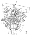
- axial piston machines 1 it is those in inclined axis construction.
- This have a closed housing 2, with a Pot-shaped housing part 3, the housing interior 4 through a so-called connector 5 is detachably closed, the by indicated screws 6 with the free edge of the housing part 3 is screwed.
- a drive shaft 7 is rotatably supported, the bottom wall 3a of the pot-shaped housing 3 in a through hole 8 interspersed.
- the cup-shaped Housing part 3 kinked in the region of its peripheral wall 3b formed so that the longitudinal central axes 9a, 9b bent against each other or arranged kinked Include an acute angle W of the housing sections.
- the drive shaft 7 is in the bottom housing section arranged and by at least one roller bearing therein stored.
- the bottom wall 3a can be formed in that in the peripheral wall 3b a sealing disc 3c sealed inserted and axially fixed, the through hole 8th the drive shaft 7 interspersed with play and through a sealing ring is sealed in it.
- roller bearings 11a, 11b for rotatable mounting of the Drive shaft 7 is provided, which in the region of the peripheral wall 3b of the bottom housing section in one appropriate bearing hole.
- Control disc 14 On the inside of the connector 5 is one Control disc 14 with two diametrically opposite one another opposite and approximately parallel to the central axis 9b of the Control disc 14 extending control channels 15, the each with a feed line and one The discharge line in the connecting part 5 are connected.
- a cylinder drum 16 At the Inside the control disc 14 is a cylinder drum 16, which has a coaxial guide hole 17 and several approximately axially parallel and distributed over the circumference arranged piston holes 18 which at their the Control channels 15 facing ends through tapered Feed and discharge channels 19 with the control channels 15 are connected.
- the pilot hole 17 and the piston holes 18 open at the end facing away from the control disk 14 Cylinder drum 16.
- Pistons 21 are axially back and forth in the piston holes 18 displaceable, preferably also slightly pendulum, stored, with the control disc 14 facing Limit ends of working chambers 22 in the piston holes 18 and with their head ends facing away from the control disk 14 protrude from the cylinder drum 16 and by means of Support joints 23, in particular ball joints, on all sides are pivotally connected to the drive shaft 7.
- the Support joints 23 are at a right angle to Central axis section 9a extending bearing plane E, the arranged at an acute angle to each other Housing sections obliquely to the central axis section 9b extends.
- a center pin 24 is formed and by a Support joint 25 pivotally connected to the drive shaft 7, which extends into the guide hole 17 and therein can be moved axially back and forth with little movement is stored.
- a compression spring 26 in particular a coil spring, which the cylinder drum 16th against the control disc 14 with a certain axial Force biased.
- the compression spring 26 in a front opening in the Center pin 24 arranged, being at the bottom of the Supporting holes and against an inner shoulder surface 27 of the Cylinder drum 16 acts.
- the support joints are 23 for the piston 21 and preferably also the support joint 25 for the center pin 24 each by one hemispherical dome 28 in the inner, preferably flat end face 29 of the drive shaft 7 and one for all Piston 21 formed common retraction plate 31, which reaches behind spherical piston ends and thus on it prevents them from entering the calottes 28.
- the Retraction disc 31 has the number and position of the calottes 28 arranged retraction holes 32, the Reach behind the associated ball head 21a and thus form-fitting against moving out of the calotte 28 prevent. Basically, it is sufficient if the Hole edges engage behind the ball heads 21a, whereby they are smaller than the diameter of the ball heads 21a or of their equator.
- the hole wall surface 32a of the retreat holes 32 so conical train that they are tangential to the associated one Ball head 21a abuts or so spherical section form that the hole wall surface 32a flat on the Spherical surface of the associated ball head 21a abuts.
- the former case results in a linear arrangement between the spherical head 21a and the perforated wall surface 32a.
- the second case arises between these two surfaces a flat system.
- the support bearing 25 for the Center pin 24 can be with a calotte 28 in the drive shaft 7 and a withdrawal hole 32 in the withdrawal disk 31 be trained accordingly.
- the retraction disc 31 is detachable on the drive shaft 7 attached, preferably screwed.
- a A plurality of cap screws 33 are used, the axially parallel Pass through holes 34 in the retraction plate 31 and in corresponding threaded holes 34a in the drive shaft 7 are screwed in.
- a ring gear 35 On the circumference of the preferably as a thin parallel disc trained retraction plate 31 is a ring gear 35 with in the circumferential direction of the same size teeth 35a and Tooth gaps 35b formed.
- a sensor 36 Housing 2 attached, the rotating operation of the Axial piston machine 1 due to the moving past it due to the teeth 35a and the tooth gaps 35b Differences signals generated in a not shown signal processing device for Speed measurement can be used.
- Such a sensor 36 is known per se and need not be described further become.
- the signals can e.g. B. by detecting Magnetic field changes are generated, which at Penetration of teeth 35a and gaps 35b of one of the Sensor associated magnetic field result. That is why advantageous, the retraction plate 31 made of metal, in particular Steel, or alloy steel.
- the sensor can also include a photosensitive member that by the teeth 35a perceives shadowing.
- the sensor 36 is preferably in the interior 4 of the housing arranged, being in the present embodiment the peripheral wall 3b from the outside in a through hole 37 grasped and z. B. is inserted or screwed in, preferably in a screwed into the peripheral wall 3b Socket 38.
- the sensor 36 is through an electrical wire 39 with an associated electronic control device connected.
- Number ring 35 markings 39 instead of Number ring 35 markings 39 of any kind provided be on which the sensor 36 for emitting signals responding.
- With a light-sensitive sensor 36 can z. B. light / dark contrast markings 39 may be provided.
- the teeth 35a extend axially parallel, whereby they can be bent accordingly.
- the radial dimension a of teeth 35a may be smaller than that in Circumferential dimension b.
- the in the Circumferential direction dimension c of the tooth gaps 35b can correspond to dimension b.
- the cross-sectional size of the drive shaft 7 is smaller can be as that occupied by the calottes 28 Cross-sectional size, it is advantageous to the drive shaft 7 their inner end facing the cylinder drum 16 to form a flange 7a in which the calottes 28 or Support joints 23 are formed.
- the markings 39 are formed by molded parts, it is advantageous to use these molded parts in one piece Form retraction plate 31, as is the case with a ring gear 35 is possible. It is further beneficial to the teeth 35a in one piece by punching on the retraction disc 31 train.
- the retraction plate can pass through Punches are made, e.g. B. by punching out a corresponding board, in particular by stamping a Sheet.
- the teeth can be bent and the edges of the holes the withdrawal holes 32 are embossed or deformed by pressure become.
- the one located in the interior 4 of the housing Fluid of the axial piston machine 1 preferably continuously to circulate.
- the previously described molded parts or teeth 35a serve as conveying elements 40, whereby they Fluid to an outlet opening 41 in the peripheral wall 3b and through a from the outlet opening 41 to a tank promote extending line (not shown).
- the teeth 35a conveying elements one Form conveyor it is advantageous to existing annular space between the conveyor elements 40 and the peripheral wall 3b larger in the region of the outlet opening 41 train than in the rest of the area or this annulus to continuously enlarge towards the outlet opening 41.
- the bearing level E on the front side of the drive shaft 7 runs, it requires a considerable thickness of the Retraction disc 31 to ensure a secure grip behind the To reach piston heads 21a.
- the Hole surfaces 32a are preferably segmented or annular bearing approaches 43 formed by the edge of the hole the withdrawal holes 32 protrude toward the drive shaft 7 and in corresponding extensions 44 of the calottes 28 protrude, which extend to about the equator of the calotte 28.
- the bearing lugs 43 are preferably formed in one piece. It can be around peripheral areas of an associated ball head 21a act accordingly in the axially protruding shape bent and / or shaped by pressure.
- Retraction plate 31 This Design allows the thickness d of Retraction plate 31 to be dimensioned small, z. B. smaller than that axial length of the bearing lugs 43.
- Retraction disc 31 preferably a stamped part or a Stamped / bent part or stamped / molded part.
- Axial piston machine 1 with regard to its throughput volume not adjustable. It is a so-called Constant machine. 3 in the embodiment the throughput volume of the axial piston machine can be reduced or expandable.
- a known, adjusting device generally designated 45 with a Adjustment member 46, the z. B. with the control disc 14 in Operational connection is established and with which the cylinder drum 16 between a minimum position and a maximum position adjustable and preferably also in intermediate positions is adjustable.
- the minimum and maximum position is through lateral stops 47, 48 limited by the Circumferential wall 3b formed adjusting screws could be.
Landscapes
- Engineering & Computer Science (AREA)
- Mechanical Engineering (AREA)
- General Engineering & Computer Science (AREA)
- Reciprocating Pumps (AREA)
- Pistons, Piston Rings, And Cylinders (AREA)
Description
- Fig. 1
- eine erfindungsgemäße Axialkolbenmaschine im axialen Schnitt;
- Fig. 2
- eine Rückzugsscheibe in der Vorderansicht; und
- Fig. 3
- eine erfindungsgemäße Axialkolbenmaschine im Axialschnitt in abgewandelter Ausgestaltung.
Claims (8)
- Axialkolbenmaschine (1) mit einem Gehäuse (2), in dessen Gehäuseinnenraum (4) eine Triebwelle (7) und eine axial neben ihr angeordnete Zylindertrommel (16) drehbar gelagert sind, wobei die Längsmittelachsen (9a, 9b) der Triebwelle (7) und der Zylindertrommel (17) um einen Winkel (W) schräg zueinander verlaufen, wobei in der Zylindertrommel (16) mehrere, sich etwa parallel zu ihrer Mittelachse (9b) erstreckende Kolbenlöcher (18) angeordnet sind, in denen Kolben (21) axial hin und her verschiebbar geführt sind, deren der Triebwelle (7) zugewandte Kolbenenden allseitig schwenkbar durch Stützgelenke (25) mit der Triebwelle (7) verbunden sind, wobei eine für alle Stützgelenke (23) gemeinsame Rückzugscheibe (31) vorgesehen ist, die die Kolbenenden daran hindert, sich von den Stützgelenken (23) axial zu entfernen, und wobei Förderelemente (40) zum Fördern des im Gehäuseinnenraum (4) befindlichen Fluids an einem im Funktionsbetrieb mit der Triebwelle (7) drehenden Bauteil in dessen Umfangsrichtung verteilt angeordnet sind,
dadurch gekennzeichnet, daß die Förderelemente (40) im Umfangsbereich der Rückzugscheibe (31) angeordnet sind. - Axialkolbenmaschine nach Anspruch 1,
dadurch gekennzeichnet, daß die Förderelemente (40) durch einen Zahnkranz (35) gebildet sind. - Axialkolbenmaschine nach Anspruch 2,
dadurch gekennzeichnet,
die Förderelemente (40) oder Zähne (35a) radial oder axial von der Rückzugscheibe (31) abstehen. - Axialkolbenmaschine nach Anspruch 3,
dadurch gekennzeichnet, daß die Förderelemente (40) oder Zähne (35a) durch Stanzen einteilig an der Rückzugscheibe (31) ausgebildet sind. - Axialkolbenmaschine nach Anspruch 3 oder 4,
dadurch gekennzeichnet, daß die Förderelemente (40) oder Zähne (35a) am Umfang der Rückzugscheibe (31) angeordnet sind und axial umgebogen sind. - Axialkolbenmaschine nach Anspruch 1,
dadurch gekennzeichnet, daß ein Sensor (36) im Gehäuseinnenraum (4) angeordnet ist, vorzugsweise sich von außen durch ein Durchführungsloch (37) im Gehäuse (2) nach innen erstreckt. - Axialkolbenmaschine nach Anspruch 6,
dadurch gekennzeichnet, daß im den Förderelementen (40) oder Zähnen (35a) benachbarten Bereich des Gehäuses (2) ein Auslaßloch (41) angeordnet ist, das vorzugsweise durch ein Verschlußteil, z. B. einen Schraubstopfen, verschließbar ist. - Axialkolbenmaschine nach Anspruch 7,
dadurch gekennzeichnet, daß das Auslaßloch (41) sich in einem Wandbereich (42) des Gehäuses (2) befindet, der einen sich in der Umfangsrichtung zum Auslaßloch (41) hin vergrößernden Ringraum zwischen den Förderelementen (40) oder Zähnen (35a) und dem Gehäuse (2) begrenzt.
Priority Applications (1)
| Application Number | Priority Date | Filing Date | Title |
|---|---|---|---|
| EP04007090A EP1433954B1 (de) | 2000-06-20 | 2001-03-15 | Axialkolbenmaschine |
Applications Claiming Priority (3)
| Application Number | Priority Date | Filing Date | Title |
|---|---|---|---|
| DE10030147 | 2000-06-20 | ||
| DE10030147A DE10030147C1 (de) | 2000-06-20 | 2000-06-20 | Axialkolbenmaschine |
| PCT/EP2001/002950 WO2001098656A1 (de) | 2000-06-20 | 2001-03-15 | Axialkolbenmaschine |
Related Child Applications (1)
| Application Number | Title | Priority Date | Filing Date |
|---|---|---|---|
| EP04007090.6 Division-Into | 2004-03-24 |
Publications (2)
| Publication Number | Publication Date |
|---|---|
| EP1292768A1 EP1292768A1 (de) | 2003-03-19 |
| EP1292768B1 true EP1292768B1 (de) | 2004-11-24 |
Family
ID=7646246
Family Applications (2)
| Application Number | Title | Priority Date | Filing Date |
|---|---|---|---|
| EP04007090A Expired - Lifetime EP1433954B1 (de) | 2000-06-20 | 2001-03-15 | Axialkolbenmaschine |
| EP01925467A Expired - Lifetime EP1292768B1 (de) | 2000-06-20 | 2001-03-15 | Axialkolbenmaschine |
Family Applications Before (1)
| Application Number | Title | Priority Date | Filing Date |
|---|---|---|---|
| EP04007090A Expired - Lifetime EP1433954B1 (de) | 2000-06-20 | 2001-03-15 | Axialkolbenmaschine |
Country Status (4)
| Country | Link |
|---|---|
| US (1) | US6779433B2 (de) |
| EP (2) | EP1433954B1 (de) |
| DE (3) | DE10030147C1 (de) |
| WO (1) | WO2001098656A1 (de) |
Families Citing this family (21)
| Publication number | Priority date | Publication date | Assignee | Title |
|---|---|---|---|---|
| WO2004109107A1 (de) * | 2003-06-11 | 2004-12-16 | Brueninghaus Hydromatik Gmbh | Axialkolbenmaschine mit versetztem positionierelement und steuerscheibe für eine solche axialkolbenmaschine |
| DE10347086A1 (de) * | 2003-06-11 | 2005-01-05 | Brueninghaus Hydromatik Gmbh | Axialkolbenmaschine mit versetztem Positionierelement und Steuerscheibe für eine solche Axialkolbenmaschine |
| DE10347085B3 (de) * | 2003-10-10 | 2005-06-16 | Brueninghaus Hydromatik Gmbh | Hydrostatische Kolbenmaschine mit zwei hydraulischen Kreisläufen |
| DE102004010351B4 (de) * | 2004-03-03 | 2006-02-09 | Sauer-Danfoss (Neumünster) GmbH & Co OHG | Hydrostatische Verstelleinheit mit Schrägscheibe, rotierendem Zylinderblock und einem Drehzahlgeber |
| US7275474B2 (en) * | 2005-05-31 | 2007-10-02 | Parker-Hannifincorporation | Optical position sensing and method |
| US8161924B1 (en) | 2006-04-17 | 2012-04-24 | James Lockshaw | Orbital, non-reciprocating, internal combustion engine |
| US7721687B1 (en) | 2006-04-17 | 2010-05-25 | James Lockshaw | Non-reciprocating, orbital, internal combustion engine |
| DE102009058332B4 (de) * | 2009-12-15 | 2019-11-28 | Robert Bosch Gmbh | Axialkolbenmaschine |
| DE102010026182A1 (de) * | 2010-07-06 | 2012-01-12 | Robert Bosch Gmbh | Kolbenmaschine mit einem Sensor zur Drehzahlerfassung |
| US8555830B2 (en) | 2011-10-14 | 2013-10-15 | James Lockshaw | Orbital, non-reciprocating, internal combustion engine |
| JP5063823B1 (ja) * | 2012-04-13 | 2012-10-31 | 株式会社小松製作所 | 斜軸式アキシャルピストンポンプ・モータ |
| DE102012016069A1 (de) * | 2012-08-14 | 2014-02-20 | Robert Bosch Gmbh | Rohteil, Triebwelle, Hydrostatische Maschine und Verfahren zur Herstellung einer Triebwelle für eine hydrostatische Maschine |
| EP3020969B1 (de) | 2014-11-11 | 2017-09-27 | Danfoss A/S | Pumpenanordnung |
| US9624825B1 (en) | 2015-12-02 | 2017-04-18 | James Lockshaw | Orbital non-reciprocating internal combustion engine |
| JP6800192B2 (ja) * | 2018-09-28 | 2020-12-16 | 本田技研工業株式会社 | 内燃機関の回転数検出装置 |
| DE102019202483A1 (de) * | 2019-02-25 | 2020-08-27 | Robert Bosch Gmbh | Axialkolbenmaschine mit einstückiger Zählperforation |
| CN113833739A (zh) * | 2021-09-28 | 2021-12-24 | 杭州力龙液压有限公司 | 传动轴、液压马达及工程机械 |
| JP7774422B2 (ja) * | 2021-11-09 | 2025-11-21 | 川崎重工業株式会社 | シリンダブロック、及びそれを備える液圧装置 |
| JP7738461B2 (ja) * | 2021-11-09 | 2025-09-12 | 川崎重工業株式会社 | 液圧システム |
| US12372074B1 (en) * | 2024-07-23 | 2025-07-29 | Hamilton Sundstrand Corporation | Piston retainer plate |
| DE102024207593A1 (de) * | 2024-08-09 | 2026-02-12 | Robert Bosch Gesellschaft mit beschränkter Haftung | Axialkolbenmaschine in Schrägachsenbauweise mit Vorkompressionsvolumen |
Family Cites Families (7)
| Publication number | Priority date | Publication date | Assignee | Title |
|---|---|---|---|---|
| US4655689A (en) * | 1985-09-20 | 1987-04-07 | General Signal Corporation | Electronic control system for a variable displacement pump |
| JPS62201366A (ja) * | 1986-02-28 | 1987-09-05 | Diesel Kiki Co Ltd | 圧縮機の回転速度検出装置 |
| US5073091A (en) * | 1989-09-25 | 1991-12-17 | Vickers, Incorporated | Power transmission |
| US5135031A (en) * | 1989-09-25 | 1992-08-04 | Vickers, Incorporated | Power transmission |
| DE4215869C2 (de) * | 1992-05-14 | 1996-01-11 | Hydromatik Gmbh | Hydrostatische Maschine mit Leckölabführung |
| DE9408860U1 (de) * | 1994-05-31 | 1994-07-21 | INA Wälzlager Schaeffler KG, 91074 Herzogenaurach | Axialkolbenmaschine |
| DE19649195C1 (de) * | 1996-11-27 | 1998-01-08 | Brueninghaus Hydromatik Gmbh | Axialkolbenmaschine mit Lagerspülung |
-
2000
- 2000-06-20 DE DE10030147A patent/DE10030147C1/de not_active Expired - Fee Related
-
2001
- 2001-03-15 WO PCT/EP2001/002950 patent/WO2001098656A1/de not_active Ceased
- 2001-03-15 DE DE50104620T patent/DE50104620D1/de not_active Expired - Fee Related
- 2001-03-15 DE DE50105498T patent/DE50105498D1/de not_active Expired - Fee Related
- 2001-03-15 EP EP04007090A patent/EP1433954B1/de not_active Expired - Lifetime
- 2001-03-15 US US10/275,629 patent/US6779433B2/en not_active Expired - Fee Related
- 2001-03-15 EP EP01925467A patent/EP1292768B1/de not_active Expired - Lifetime
Also Published As
| Publication number | Publication date |
|---|---|
| US20030136359A1 (en) | 2003-07-24 |
| EP1433954B1 (de) | 2005-03-02 |
| DE10030147C1 (de) | 2002-06-06 |
| DE50104620D1 (de) | 2004-12-30 |
| WO2001098656A1 (de) | 2001-12-27 |
| US6779433B2 (en) | 2004-08-24 |
| EP1292768A1 (de) | 2003-03-19 |
| DE50105498D1 (de) | 2005-04-07 |
| EP1433954A1 (de) | 2004-06-30 |
Similar Documents
| Publication | Publication Date | Title |
|---|---|---|
| DE10030147C1 (de) | Axialkolbenmaschine | |
| DE68920548T2 (de) | Zahnstangenlenkeinrichtung. | |
| EP3081744B1 (de) | Pumpe mit axialer druckfeder | |
| DE3716407A1 (de) | Hydraulische uebertragungsvorrichtung | |
| EP1886035B1 (de) | Schrägscheiben-schwenklager | |
| DE60129590T3 (de) | Magnetpumpe | |
| DE2534539C3 (de) | ||
| DE4040200A1 (de) | Kuehlwasserpumpe zur verwendung an dem pumpengehaeuse einer brennkraftmaschine | |
| DE10207118B4 (de) | Lagermechanismus und Pumpe | |
| DE10220610A1 (de) | Drehgleitlager | |
| DE102006055161A1 (de) | Lagerschale für eine hydrostatische Maschine und hydrostatische Maschine mit dieser Lagerschale | |
| EP1251270B1 (de) | Axialkolbenmaschine in Schrägachsen-Bauweise mit einem Schwenkwinkel-Sensor | |
| DE19834033A1 (de) | Vakuumpumpe | |
| EP0474001B1 (de) | Innenzahnradpumpe für Hydraulikflüssigkeit | |
| EP2002169B1 (de) | Schmiermittel- oder hydraulikpumpe | |
| EP0475109B1 (de) | Innenzahnradpumpe für Hydraulikflüssigkeit | |
| DE10017780B4 (de) | Kolbenmaschine | |
| DE60110314T2 (de) | Axialkolbenpumpe | |
| DE102017124024B3 (de) | Nehmerzylinder mit Metallbestandteil am Sensorgehäusebereich, Betätigungseinrichtung sowie Kupplungssystem | |
| EP0607509A1 (de) | Vorrichtung zur Winkelverstellung einer Welle gegenüber ihrem Antriebsrad, insbesondere einer Nockenwelle gegenüber ihrem Nockenwellenrad | |
| EP3249156A1 (de) | Maschine, insbesondere ölförderpumpe | |
| DE102004005204A1 (de) | Radialkolbenpumpe | |
| DE19910659C2 (de) | Hydraulische Kolbenmaschineneinheit | |
| EP4474644B1 (de) | Peristaltikpumpe | |
| DE102019202336A1 (de) | Exzenterantrieb einer Exzenterpumpe |
Legal Events
| Date | Code | Title | Description |
|---|---|---|---|
| PUAI | Public reference made under article 153(3) epc to a published international application that has entered the european phase |
Free format text: ORIGINAL CODE: 0009012 |
|
| 17P | Request for examination filed |
Effective date: 20020919 |
|
| AK | Designated contracting states |
Kind code of ref document: A1 Designated state(s): AT BE CH CY DE DK ES FI FR GB GR IE IT LI LU MC NL PT SE TR |
|
| 17Q | First examination report despatched |
Effective date: 20031216 |
|
| RBV | Designated contracting states (corrected) |
Designated state(s): AT BE CH CY DE FR GB IT LI SE |
|
| GRAP | Despatch of communication of intention to grant a patent |
Free format text: ORIGINAL CODE: EPIDOSNIGR1 |
|
| RBV | Designated contracting states (corrected) |
Designated state(s): DE FR GB IT SE |
|
| GRAS | Grant fee paid |
Free format text: ORIGINAL CODE: EPIDOSNIGR3 |
|
| GRAA | (expected) grant |
Free format text: ORIGINAL CODE: 0009210 |
|
| AK | Designated contracting states |
Kind code of ref document: B1 Designated state(s): DE FR GB IT SE |
|
| REG | Reference to a national code |
Ref country code: GB Ref legal event code: FG4D Free format text: NOT ENGLISH |
|
| REF | Corresponds to: |
Ref document number: 50104620 Country of ref document: DE Date of ref document: 20041230 Kind code of ref document: P |
|
| REG | Reference to a national code |
Ref country code: IE Ref legal event code: FG4D Free format text: GERMAN |
|
| REG | Reference to a national code |
Ref country code: SE Ref legal event code: TRGR |
|
| REG | Reference to a national code |
Ref country code: IE Ref legal event code: FD4D |
|
| PLBE | No opposition filed within time limit |
Free format text: ORIGINAL CODE: 0009261 |
|
| STAA | Information on the status of an ep patent application or granted ep patent |
Free format text: STATUS: NO OPPOSITION FILED WITHIN TIME LIMIT |
|
| ET | Fr: translation filed | ||
| 26N | No opposition filed |
Effective date: 20050825 |
|
| PGFP | Annual fee paid to national office [announced via postgrant information from national office to epo] |
Ref country code: SE Payment date: 20070313 Year of fee payment: 7 |
|
| PGFP | Annual fee paid to national office [announced via postgrant information from national office to epo] |
Ref country code: DE Payment date: 20070316 Year of fee payment: 7 |
|
| PGFP | Annual fee paid to national office [announced via postgrant information from national office to epo] |
Ref country code: GB Payment date: 20070322 Year of fee payment: 7 |
|
| PGFP | Annual fee paid to national office [announced via postgrant information from national office to epo] |
Ref country code: IT Payment date: 20070623 Year of fee payment: 7 |
|
| PGFP | Annual fee paid to national office [announced via postgrant information from national office to epo] |
Ref country code: FR Payment date: 20070319 Year of fee payment: 7 |
|
| EUG | Se: european patent has lapsed | ||
| GBPC | Gb: european patent ceased through non-payment of renewal fee |
Effective date: 20080315 |
|
| REG | Reference to a national code |
Ref country code: FR Ref legal event code: ST Effective date: 20081125 |
|
| PG25 | Lapsed in a contracting state [announced via postgrant information from national office to epo] |
Ref country code: SE Free format text: LAPSE BECAUSE OF NON-PAYMENT OF DUE FEES Effective date: 20080316 Ref country code: DE Free format text: LAPSE BECAUSE OF NON-PAYMENT OF DUE FEES Effective date: 20081001 |
|
| PG25 | Lapsed in a contracting state [announced via postgrant information from national office to epo] |
Ref country code: FR Free format text: LAPSE BECAUSE OF NON-PAYMENT OF DUE FEES Effective date: 20080331 |
|
| PG25 | Lapsed in a contracting state [announced via postgrant information from national office to epo] |
Ref country code: GB Free format text: LAPSE BECAUSE OF NON-PAYMENT OF DUE FEES Effective date: 20080315 |
|
| PG25 | Lapsed in a contracting state [announced via postgrant information from national office to epo] |
Ref country code: IT Free format text: LAPSE BECAUSE OF NON-PAYMENT OF DUE FEES Effective date: 20080315 |