EP1291500B1 - Abgasanlage für mehrzylindrige Verbrennungsmotoren - Google Patents
Abgasanlage für mehrzylindrige Verbrennungsmotoren Download PDFInfo
- Publication number
- EP1291500B1 EP1291500B1 EP02017485A EP02017485A EP1291500B1 EP 1291500 B1 EP1291500 B1 EP 1291500B1 EP 02017485 A EP02017485 A EP 02017485A EP 02017485 A EP02017485 A EP 02017485A EP 1291500 B1 EP1291500 B1 EP 1291500B1
- Authority
- EP
- European Patent Office
- Prior art keywords
- exhaust gas
- exhaust
- pipe arrangement
- housing
- pipes
- Prior art date
- Legal status (The legal status is an assumption and is not a legal conclusion. Google has not performed a legal analysis and makes no representation as to the accuracy of the status listed.)
- Expired - Lifetime
Links
Images


Classifications
-
- F—MECHANICAL ENGINEERING; LIGHTING; HEATING; WEAPONS; BLASTING
- F01—MACHINES OR ENGINES IN GENERAL; ENGINE PLANTS IN GENERAL; STEAM ENGINES
- F01N—GAS-FLOW SILENCERS OR EXHAUST APPARATUS FOR MACHINES OR ENGINES IN GENERAL; GAS-FLOW SILENCERS OR EXHAUST APPARATUS FOR INTERNAL-COMBUSTION ENGINES
- F01N13/00—Exhaust or silencing apparatus characterised by constructional features
- F01N13/18—Construction facilitating manufacture, assembly, or disassembly
- F01N13/1883—Construction facilitating manufacture, assembly, or disassembly manufactured by hydroforming
-
- F—MECHANICAL ENGINEERING; LIGHTING; HEATING; WEAPONS; BLASTING
- F01—MACHINES OR ENGINES IN GENERAL; ENGINE PLANTS IN GENERAL; STEAM ENGINES
- F01N—GAS-FLOW SILENCERS OR EXHAUST APPARATUS FOR MACHINES OR ENGINES IN GENERAL; GAS-FLOW SILENCERS OR EXHAUST APPARATUS FOR INTERNAL-COMBUSTION ENGINES
- F01N13/00—Exhaust or silencing apparatus characterised by constructional features
- F01N13/008—Mounting or arrangement of exhaust sensors in or on exhaust apparatus
-
- F—MECHANICAL ENGINEERING; LIGHTING; HEATING; WEAPONS; BLASTING
- F01—MACHINES OR ENGINES IN GENERAL; ENGINE PLANTS IN GENERAL; STEAM ENGINES
- F01N—GAS-FLOW SILENCERS OR EXHAUST APPARATUS FOR MACHINES OR ENGINES IN GENERAL; GAS-FLOW SILENCERS OR EXHAUST APPARATUS FOR INTERNAL-COMBUSTION ENGINES
- F01N13/00—Exhaust or silencing apparatus characterised by constructional features
- F01N13/08—Other arrangements or adaptations of exhaust conduits
-
- F—MECHANICAL ENGINEERING; LIGHTING; HEATING; WEAPONS; BLASTING
- F01—MACHINES OR ENGINES IN GENERAL; ENGINE PLANTS IN GENERAL; STEAM ENGINES
- F01N—GAS-FLOW SILENCERS OR EXHAUST APPARATUS FOR MACHINES OR ENGINES IN GENERAL; GAS-FLOW SILENCERS OR EXHAUST APPARATUS FOR INTERNAL-COMBUSTION ENGINES
- F01N13/00—Exhaust or silencing apparatus characterised by constructional features
- F01N13/08—Other arrangements or adaptations of exhaust conduits
- F01N13/10—Other arrangements or adaptations of exhaust conduits of exhaust manifolds
-
- F—MECHANICAL ENGINEERING; LIGHTING; HEATING; WEAPONS; BLASTING
- F01—MACHINES OR ENGINES IN GENERAL; ENGINE PLANTS IN GENERAL; STEAM ENGINES
- F01N—GAS-FLOW SILENCERS OR EXHAUST APPARATUS FOR MACHINES OR ENGINES IN GENERAL; GAS-FLOW SILENCERS OR EXHAUST APPARATUS FOR INTERNAL-COMBUSTION ENGINES
- F01N13/00—Exhaust or silencing apparatus characterised by constructional features
- F01N13/08—Other arrangements or adaptations of exhaust conduits
- F01N13/10—Other arrangements or adaptations of exhaust conduits of exhaust manifolds
- F01N13/102—Other arrangements or adaptations of exhaust conduits of exhaust manifolds having thermal insulation
-
- F—MECHANICAL ENGINEERING; LIGHTING; HEATING; WEAPONS; BLASTING
- F01—MACHINES OR ENGINES IN GENERAL; ENGINE PLANTS IN GENERAL; STEAM ENGINES
- F01N—GAS-FLOW SILENCERS OR EXHAUST APPARATUS FOR MACHINES OR ENGINES IN GENERAL; GAS-FLOW SILENCERS OR EXHAUST APPARATUS FOR INTERNAL-COMBUSTION ENGINES
- F01N13/00—Exhaust or silencing apparatus characterised by constructional features
- F01N13/08—Other arrangements or adaptations of exhaust conduits
- F01N13/10—Other arrangements or adaptations of exhaust conduits of exhaust manifolds
- F01N13/107—More than one exhaust manifold or exhaust collector
-
- F—MECHANICAL ENGINEERING; LIGHTING; HEATING; WEAPONS; BLASTING
- F01—MACHINES OR ENGINES IN GENERAL; ENGINE PLANTS IN GENERAL; STEAM ENGINES
- F01N—GAS-FLOW SILENCERS OR EXHAUST APPARATUS FOR MACHINES OR ENGINES IN GENERAL; GAS-FLOW SILENCERS OR EXHAUST APPARATUS FOR INTERNAL-COMBUSTION ENGINES
- F01N13/00—Exhaust or silencing apparatus characterised by constructional features
- F01N13/14—Exhaust or silencing apparatus characterised by constructional features having thermal insulation
-
- F—MECHANICAL ENGINEERING; LIGHTING; HEATING; WEAPONS; BLASTING
- F01—MACHINES OR ENGINES IN GENERAL; ENGINE PLANTS IN GENERAL; STEAM ENGINES
- F01N—GAS-FLOW SILENCERS OR EXHAUST APPARATUS FOR MACHINES OR ENGINES IN GENERAL; GAS-FLOW SILENCERS OR EXHAUST APPARATUS FOR INTERNAL-COMBUSTION ENGINES
- F01N13/00—Exhaust or silencing apparatus characterised by constructional features
- F01N13/18—Construction facilitating manufacture, assembly, or disassembly
- F01N13/1888—Construction facilitating manufacture, assembly, or disassembly the housing of the assembly consisting of two or more parts, e.g. two half-shells
-
- F—MECHANICAL ENGINEERING; LIGHTING; HEATING; WEAPONS; BLASTING
- F01—MACHINES OR ENGINES IN GENERAL; ENGINE PLANTS IN GENERAL; STEAM ENGINES
- F01N—GAS-FLOW SILENCERS OR EXHAUST APPARATUS FOR MACHINES OR ENGINES IN GENERAL; GAS-FLOW SILENCERS OR EXHAUST APPARATUS FOR INTERNAL-COMBUSTION ENGINES
- F01N3/00—Exhaust or silencing apparatus having means for purifying, rendering innocuous, or otherwise treating exhaust
- F01N3/08—Exhaust or silencing apparatus having means for purifying, rendering innocuous, or otherwise treating exhaust for rendering innocuous
- F01N3/10—Exhaust or silencing apparatus having means for purifying, rendering innocuous, or otherwise treating exhaust for rendering innocuous by thermal or catalytic conversion of noxious components of exhaust
- F01N3/24—Exhaust or silencing apparatus having means for purifying, rendering innocuous, or otherwise treating exhaust for rendering innocuous by thermal or catalytic conversion of noxious components of exhaust characterised by constructional aspects of converting apparatus
- F01N3/28—Construction of catalytic reactors
-
- F—MECHANICAL ENGINEERING; LIGHTING; HEATING; WEAPONS; BLASTING
- F01—MACHINES OR ENGINES IN GENERAL; ENGINE PLANTS IN GENERAL; STEAM ENGINES
- F01N—GAS-FLOW SILENCERS OR EXHAUST APPARATUS FOR MACHINES OR ENGINES IN GENERAL; GAS-FLOW SILENCERS OR EXHAUST APPARATUS FOR INTERNAL-COMBUSTION ENGINES
- F01N3/00—Exhaust or silencing apparatus having means for purifying, rendering innocuous, or otherwise treating exhaust
- F01N3/08—Exhaust or silencing apparatus having means for purifying, rendering innocuous, or otherwise treating exhaust for rendering innocuous
- F01N3/10—Exhaust or silencing apparatus having means for purifying, rendering innocuous, or otherwise treating exhaust for rendering innocuous by thermal or catalytic conversion of noxious components of exhaust
- F01N3/24—Exhaust or silencing apparatus having means for purifying, rendering innocuous, or otherwise treating exhaust for rendering innocuous by thermal or catalytic conversion of noxious components of exhaust characterised by constructional aspects of converting apparatus
- F01N3/28—Construction of catalytic reactors
- F01N3/2892—Exhaust flow directors or the like, e.g. upstream of catalytic device
-
- F—MECHANICAL ENGINEERING; LIGHTING; HEATING; WEAPONS; BLASTING
- F01—MACHINES OR ENGINES IN GENERAL; ENGINE PLANTS IN GENERAL; STEAM ENGINES
- F01N—GAS-FLOW SILENCERS OR EXHAUST APPARATUS FOR MACHINES OR ENGINES IN GENERAL; GAS-FLOW SILENCERS OR EXHAUST APPARATUS FOR INTERNAL-COMBUSTION ENGINES
- F01N13/00—Exhaust or silencing apparatus characterised by constructional features
- F01N13/18—Construction facilitating manufacture, assembly, or disassembly
- F01N13/1805—Fixing exhaust manifolds, exhaust pipes or pipe sections to each other, to engine or to vehicle body
-
- F—MECHANICAL ENGINEERING; LIGHTING; HEATING; WEAPONS; BLASTING
- F01—MACHINES OR ENGINES IN GENERAL; ENGINE PLANTS IN GENERAL; STEAM ENGINES
- F01N—GAS-FLOW SILENCERS OR EXHAUST APPARATUS FOR MACHINES OR ENGINES IN GENERAL; GAS-FLOW SILENCERS OR EXHAUST APPARATUS FOR INTERNAL-COMBUSTION ENGINES
- F01N2240/00—Combination or association of two or more different exhaust treating devices, or of at least one such device with an auxiliary device, not covered by indexing codes F01N2230/00 or F01N2250/00, one of the devices being
- F01N2240/20—Combination or association of two or more different exhaust treating devices, or of at least one such device with an auxiliary device, not covered by indexing codes F01N2230/00 or F01N2250/00, one of the devices being a flow director or deflector
-
- F—MECHANICAL ENGINEERING; LIGHTING; HEATING; WEAPONS; BLASTING
- F01—MACHINES OR ENGINES IN GENERAL; ENGINE PLANTS IN GENERAL; STEAM ENGINES
- F01N—GAS-FLOW SILENCERS OR EXHAUST APPARATUS FOR MACHINES OR ENGINES IN GENERAL; GAS-FLOW SILENCERS OR EXHAUST APPARATUS FOR INTERNAL-COMBUSTION ENGINES
- F01N2260/00—Exhaust treating devices having provisions not otherwise provided for
- F01N2260/08—Exhaust treating devices having provisions not otherwise provided for for preventing heat loss or temperature drop, using other means than layers of heat-insulating material
-
- F—MECHANICAL ENGINEERING; LIGHTING; HEATING; WEAPONS; BLASTING
- F01—MACHINES OR ENGINES IN GENERAL; ENGINE PLANTS IN GENERAL; STEAM ENGINES
- F01N—GAS-FLOW SILENCERS OR EXHAUST APPARATUS FOR MACHINES OR ENGINES IN GENERAL; GAS-FLOW SILENCERS OR EXHAUST APPARATUS FOR INTERNAL-COMBUSTION ENGINES
- F01N2260/00—Exhaust treating devices having provisions not otherwise provided for
- F01N2260/10—Exhaust treating devices having provisions not otherwise provided for for avoiding stress caused by expansions or contractions due to temperature variations
-
- F—MECHANICAL ENGINEERING; LIGHTING; HEATING; WEAPONS; BLASTING
- F01—MACHINES OR ENGINES IN GENERAL; ENGINE PLANTS IN GENERAL; STEAM ENGINES
- F01N—GAS-FLOW SILENCERS OR EXHAUST APPARATUS FOR MACHINES OR ENGINES IN GENERAL; GAS-FLOW SILENCERS OR EXHAUST APPARATUS FOR INTERNAL-COMBUSTION ENGINES
- F01N2470/00—Structure or shape of exhaust gas passages, pipes or tubes
- F01N2470/10—Tubes having non-circular cross section
-
- F—MECHANICAL ENGINEERING; LIGHTING; HEATING; WEAPONS; BLASTING
- F01—MACHINES OR ENGINES IN GENERAL; ENGINE PLANTS IN GENERAL; STEAM ENGINES
- F01N—GAS-FLOW SILENCERS OR EXHAUST APPARATUS FOR MACHINES OR ENGINES IN GENERAL; GAS-FLOW SILENCERS OR EXHAUST APPARATUS FOR INTERNAL-COMBUSTION ENGINES
- F01N2470/00—Structure or shape of exhaust gas passages, pipes or tubes
- F01N2470/30—Tubes with restrictions, i.e. venturi or the like, e.g. for sucking air or measuring mass flow
Definitions
- the present invention relates to an exhaust system according to the preamble of claim 1.
- Such an exhaust system is made Kandylas, JP et al. "Engine exhaust system design based on heat transfer computation", Energy Conversion and Management, Elsevier Science Publishers, Oxford, GB, Vol. 40, No. 10, July 1999 (1999-07), pages 1057-1072 , XP 004162444, JSSN: 0196-8904.
- the invention has for its object to provide an exhaust system of the type mentioned that meets the requirements as well as possible.
- an exhaust system is to be created, which takes up little space in the engine compartment and has a good cleaning effect.
- the double pipe arrangement is led to just before the so-called lambda probe of the catalytic converter.
- the long Zweiflutmaschine has the advantage that the cylinders influence each other less, since there are fewer overlaps in the exhaust gas flows.
- the lambda probe is arranged in the flow sleeve, ie in a region in which the exhaust gas flow is already redesigned.
- the measured values obtained are therefore particularly meaningful.
- the flow sleeve is designed to achieve a nozzle effect preferably tapered in the direction of the catalytic converter in diameter.
- the exhaust gas flow can be particularly well designed in the desired manner.
- a further advantage is a design of the cross section of the tubes of the double tube arrangement in D-shape, wherein the tubes are facing each other with their flattened side.
- the space requirement of the double pipe arrangement can be kept low.
- Housing in a common housing is also advantageous in the branched arrangement of exhaust pipes.
- the exhaust system can thereby be kept particularly compact in the engine area.
- the two gas outlet openings of the branched exhaust pipe arrangement are arranged centrally with respect to the longitudinal direction of the arrangement. This also promotes a compact design of the exhaust system in the vicinity of the engine.
- the exhaust system is preferably constructed modularly, with a first module comprising the branched exhaust pipe arrangement and a second module comprising the double pipe arrangement.
- a first module comprising the branched exhaust pipe arrangement
- a second module comprising the double pipe arrangement.
- One Such modular construction has the advantage that partially identical components can be used for different installation situations.
- the module comprising the double tube assembly could find application in both 8-cylinder and 12-cylinder engines. Or one and the same module can be used for both right-hand drive and left-hand drive vehicles.
- a further improvement in this regard can be achieved in that the first module is formed symmetrically with respect to the center plane of the module perpendicular to the line connecting the exhaust gas inlet openings.
- the two gas outlet openings of the branched exhaust pipe arrangement are arranged centrally and pointing straight outwards, so that this module can be used on both sides of the engine and only the second, the double pipe arrangement containing module is formed side by side.
- the housing of the branched exhaust pipe arrangement and the double pipe arrangement are designed as load-bearing elements, while the exhaust pipes extending therein, in particular by means of Drahtgestrickringen, floatingly mounted and only one side firmly connected to the housing, in particular welded. It may be sufficient if the branched exhaust pipe arrangement is fixedly connected to the motor side with its housing, while the tubes of the double pipe arrangement are connected to the branched exhaust pipe arrangement and with the flow sleeve by sliding fit.
- the housings of the branched exhaust pipe arrangement, the double pipe arrangement and the flow sleeve are preferably each with each other welded.
- the flow sleeve is preferably welded to the housing of the catalytic converter.
- the attachment of the housing of the branched exhaust pipe arrangement on the engine takes place as usual by flanges. Such a configuration has proven to be advantageous both from the space and from the production ago.
- the exhaust pipes of the branched exhaust pipe assembly together with its housing in plan view of the plane of the gas inlet openings of a wavy line following such curved alternately upwards and downwards formed that in addition to the exhaust gas inlet openings for the Access to the screw holes for attaching the exhaust system to the engine are formed.
- the assembly of the exhaust system can be significantly simplified.
- the wave-shaped configuration has the advantage that thermal expansion of the fixed motor-mounted housing can be better absorbed, so that lower thermal stresses occur.
- the housing of the branched exhaust pipe assembly is divided at least once in the direction of the connecting line of the exhaust gas inlet openings, wherein the parts via flexible elements, in particular corrugated bellows, are interconnected. Also by this configuration, thermal expansion of the housing can be compensated, so that thermal stresses are reduced. This is particularly important in multi-cylinder engines, such as 12-cylinder engines, where the housing is relatively large. These are the housings preferably divided into three parts, so in particular two bellows provided.
- a common housing may also be provided.
- the manufacturing and assembly costs can be reduced.
- the housings preferably each consist of two sheet metal half shells.
- the exhaust pipes are produced in particular by hydroforming. Both are manufacturing technology advantageous.
- the in the FIGS. 1 to 5 illustrated exhaust system comprises a first with exhaust gas outlet openings of an internal combustion engine to be connected module 1, connected to the first module 1 second module 2 and connected to the second module 2 exhaust catalyst 3.
- the first module 1 comprises a housing 4, which is an arrangement of branched exhaust pipes 5 takes up.
- the branched exhaust pipes 5 each comprise two individual tubes 5 ', 5 "and 5''', with the sliding seat in one of two the exhaust gas outlet openings. 7 having manifolds 5 IV are used, wherein the manifolds 5 IV formed in the region of the exhaust gas outlet openings 7 in cross-section D-shaped and are arranged opposite each other with their flattened side.
- the housing 4 consists of two sheet-metal half shells 4 'and 4 ", which are welded together and surround the arrangement of branched exhaust pipes 5 with a small gap to form an air gap 8.
- the housing also comprises three parts 4 a, b, c, over two Bellows 9 are interconnected.
- the housing 4 has fastening flanges 10, which are partially assigned to an exhaust gas inlet opening 6, partly two exhaust gas inlet openings 6.
- the flanges 10 are connected to the housing 4 by welding.
- the arrangement of branched exhaust pipes 5 is welded to the housing 4 in the region of the exhaust gas inlet openings 6.
- the individual tubes 5 'to 5 IV are interconnected by sliding fit.
- the flanges 10 are provided in the region of each exhaust gas inlet opening 6 with two screw feedthroughs 11, by means of which the exhaust gas system can be fastened to an internal combustion engine.
- the housing 4 and the branched exhaust pipes 5 are formed in a plane parallel to the plane of the flanges 10 such a wave-shaped, that the screw penetrations 11 are kept free for a directed perpendicular to this plane access. Accordingly, the two screw penetrations 11 in the region of each exhaust gas inlet opening 6 are arranged alternately in one and the other direction opposite to each other.
- the second module 2 comprises a housing 12 made of two half-shells 12 'and 12 ", in which, as in particular in the 4 and 5 A double tube arrangement 13 is arranged from two exhaust pipes 13 'and 13 "running parallel to one another
- the two tubes 13' and 13" of the double tube arrangement are D-shaped in cross section and with their flattened sides 14 ', 14 "arranged opposite one another.
- the two exhaust pipes 13 'and 13 "of the double pipe arrangement 13, also with a sliding fit, are inserted into a flow sleeve 16, which is likewise arranged in the housing 12.
- the flow sleeve 16 is tapered in the flow direction I and has its tapered end Area 16 'a receptacle 17 for a lambda probe with its gas outlet end 18, the flow sleeve 16, again with a sliding fit, inserted into the housing 19 of the catalytic converter 3.
- All exhaust pipes 5, 13 and 16 are thus floating within the housing 4, 12. By means of wire knit rings 20, they are held in the radial direction relative to the housing 4, 12 representing the supporting parts. Only the exhaust pipes 5 ', 5 "and 5' '' of the branched exhaust pipe arrangement 5 are, as already stated, firmly connected to the housing 4 by welding on the exhaust gas inlet side.
- the catalytic converter 3 has a flange 21 for connection to further, not shown exhaust pipes.
- no further exhaust gas catalysts are preferably provided in the exhaust gas line, that is to say the entire catalyst volume is accommodated in the one exhaust gas catalytic converter 3.
- the exhaust gas outlet openings 7 of the manifolds 5 IV are arranged symmetrically about the perpendicular to the line connecting the exhaust gas inlet openings 6 extending center plane II of the module 1.
- the rest, too Elements of the first module 1 are preferably formed symmetrically with respect to this center plane II.
- the exhaust pipes 5 and 13 and the flow sleeve 16 are preferably made by hydroforming.
- the exhaust system also includes two modules 1 and 2 and an exhaust gas catalyst 3.
- the second module 2 formed in two parts, with a first part and a second part.
- the first part comprises the double tube assembly 13 and the surrounding housing 12 ', while the second part comprises the flow sleeve 16 and a separate housing 12 "surrounding it.
- the two housings 12' and 12" are joined together by welding.
- the branched exhaust pipe assembly 5 comprises two simple, curved exhaust pipes 5 ', which are inserted with sliding fit into one of two branched exhaust pipes 5 V , whose other branch forms one of the exhaust gas inlet openings 6 and the other end the exhaust gas outlet openings 7 of the branched exhaust pipe assembly 5 form.
- the two tubes 13 ', 13 "of the double tube arrangement 13 are also arranged parallel in this variant and open on the exhaust gas exit side with a sliding fit in the flow sleeve 16, which in turn has a receptacle 17 for the lambda probe in a tapered section 16' is in turn used with sliding fit into the housing 19 of the catalytic converter 3, which is preferred contains the entire catalyst volume. Again, no additional catalyst is provided in this exhaust system.
- the two tubes 13 ', 13 "of the double tube arrangement 13 are routed to the exhaust gas exit side until shortly before the lambda probe, thereby forming a mixing zone 22 in the region of the lambda probe, in which the exhaust gas flow is redesigned with the aid of the flow sleeve 16.
- the exhaust gas flow can thereby be formed in the desired manner in order to optimize the flow of the catalyst 3.
- a corresponding mixing chamber 22 is also present in the first variant.
- the entire catalyst volume is thus accommodated close to the engine. This improves the catalyst performance.
- the individual parts of the exhaust system can be used for different purposes.
- the first module 1 of the first variant can be used for both the left and the right engine side due to its symmetrical configuration with respect to the center plane II.
- the second modules 2 can each be used in conjunction with different first modules 1, for example optionally with modules 1 with four or six exhaust gas inlet openings 6.
- the invention provides a particularly compact exhaust system that can manage with an exhaust gas catalyst 3. This allows the catalyst volume to be brought very close to the engine.
- the flow sleeve 16 which acts as a mixing chamber, the exhaust gas flow can be formed and thereby optimum flow of the catalytic converter 3 can be achieved.
- the long Zweiflutmaschine through the double tube assembly 13 also has the advantage that the exhaust gas flows of the cylinder can influence less each other.
- the exhaust system according to the invention is also, in particular due to the modular structure, low in the production and, in particular because of the wavy shape of the exhaust pipes 5, in the assembly. Also, the thermal stresses in the housing 4 are reduced due to the undulating configuration.
Landscapes
- Engineering & Computer Science (AREA)
- Chemical & Material Sciences (AREA)
- General Engineering & Computer Science (AREA)
- Combustion & Propulsion (AREA)
- Mechanical Engineering (AREA)
- Chemical Kinetics & Catalysis (AREA)
- Health & Medical Sciences (AREA)
- Toxicology (AREA)
- Analytical Chemistry (AREA)
- Manufacturing & Machinery (AREA)
- Exhaust Silencers (AREA)
- Exhaust Gas After Treatment (AREA)
- Cylinder Crankcases Of Internal Combustion Engines (AREA)
Description
- Die vorliegende Erfindung betrifft eine Abgasanlage nach dem Oberbegriff von Anspruch 1. Eine solche Abgasanlage ist aus Kandylas, J.P. et al. "Engine exhaust system design based on heat transfer computation", Energy Conversion and Management, Elsevier Science Publishers, Oxford, GB, Bd. 40, Nr. 10, Juli 1999 (1999-07), Seiten 1057-1072, XP 004162444, JSSN: 0196-8904 bekannt.
- Moderne Abgasanlagen müssen eine Vielzahl von teilweise sich widersprechenden Anforderungen erfüllen. So ist zur Erzielung einer ausreichenden Abgasreinigung ein erhebliches Katalysatorvolumen erforderlich, was oftmals nur durch Aufteilung des Gesamtvolumens auf mehrere Abgaskatalysatoren erreicht werden kann. Darüberhinaus wird der im Motorraum für die Abgasanlage zur Verfügung stehende Raum aufgrund zusätzlicher Aggregate und kompakterer Bauweise immer kleiner.
- Der Erfindung liegt die Aufgabe zugrunde, eine Abgasanlage der eingangs genannten Art anzugeben, die die genannten Anforderungen möglichst gut erfüllt. Insbesondere soll eine Abgasanlage geschaffen werden, die im Motorraum wenig Platz beansprucht und eine gute Reinigungswirkung aufweist.
- Diese Aufgabe wird durch die Merkmale von Anspruch 1 gelöst.
- Durch diese Doppelrohranordnung kann eine gute Abgasreinigungsleistung bei verhältnismäßig geringem Platzbedarf erreicht werden. Insbesondere ist es aufgrund dieser Ausgestaltung möglich, das gesamte Katalysatorvolumen für eine Motorseite in einem einzigen Katalysatorgehäuse unterzubringen. Es wird also kein Vorkatalysator und kein Unterbodenkatalysator benötigt, wie dies sonst oftmals der Fall ist. Damit werden nicht nur der Platzbedarf verringert und die Kosten gesenkt, sondern es entfällt auch eine doppelte Katalysatorregelung. Zudem kann das Katalysatorvolumen insgesamt besonders nahe an den Motor herangebracht werden, was der Reinigungsleistung des Katalysators zugute kommt. In der Strömungshülse ist dabei eine Mischzone geschaffen, in welcher die Strömung neu gestaltet wird, um eine optimale Katalysatoranströmung zu erreichen.
- Bevorzugt ist die Doppelrohranordnung bis kurz vor die sogenannte Lambdasonde des Abgaskatalysators geführt. Damit ergibt sich eine besonders lange Zweiflutigkeit, die für die Abgasreinigung von Vorteil ist. Außerdem hat die lange Zweiflutigkeit den Vorteil, daß sich die Zylinder gegenseitig weniger beeinflussen, da weniger Überschneidungen bei den Abgasströmungen auftreten.
- Die Lambdasonde ist in der Strömungshülse angeordnet, also in einem Bereich, in dem die Abgasströmung bereits neu gestaltet ist. Die erhaltenen Meßwerte sind dadurch besonders aussagekräftig.
- Die Strömungshülse ist zur Erzielung einer Düsenwirkung bevorzugt in Richtung auf den Abgaskatalysator im Durchmesser verjüngt ausgebildet. Damit kann die Abgasströmung besonders gut in gewünschter Weise ausgestaltet werden.
- Vorteilhaft ist weiterhin eine Ausbildung des Querschnitts der Rohre der Doppelrohranordnung in D-Form, wobei die Rohre mit ihrer abgeflachten Seite einander zugewandt sind. Der Platzbedarf der Doppelrohranordnung kann dadurch gering gehalten werden.
- Eine weitere Verringerung des Platzbedarfes ergibt sich, wenn die beiden Rohre der Doppelrohranordnung in einem gemeinsamen Gehäuse untergebracht sind.
- Die Unterbringung in einem gemeinsamen Gehäuse ist auch bei der verzweigten Anordnung aus Abgasrohren vorteilhaft. Insbesondere kann die Abgasanlage dadurch im Motorbereich besonders kompakt gehalten werden.
- Nach der Erfindung sind die beiden Gasaustrittsöffnungen der verzweigten Abgasrohranordnung in Bezug auf die Längsrichtung der Anordnung mittig angeordnet. Auch dies fördert einen kompakten Aufbau der Abgasanlage im motornahen Bereich.
- Des weiteren ist die Abgasanlage bevorzugt modulartig aufgebaut, mit einem ersten, die verzweigte Abgasrohranordnung umfassenden Modul und einem zweiten, die Doppelrohranordnung umfassenden Modul. Ein solcher modulartiger Aufbau hat den Vorteil, daß für verschiedene Einbausituationen teilweise gleiche Bauteile verwendet werden können. Beispielsweise könnte das die Doppelrohranordnung umfassende Modul sowohl bei 8-Zylinder- als auch bei 12-Zylinder-Motoren Anwendung finden. Oder es kann ein und dasselbe Modul sowohl für Rechtslenker als auch für Linkslenker verwendet werden.
- Eine weitere Verbesserung in dieser Hinsicht kann dadurch erreicht werden, daß das erste Modul in Bezug auf die zur Verbindungslinie der Abgaseintrittsöffnungen senkrechte Mittelebene des Moduls symmetrisch ausgebildet ist. Dies heißt insbesondere, daß die beiden Gasaustrittsöffnungen der verzweigten Abgasrohranordnung mittig und gerade nach außen weisend angeordnet sind, so daß dieses Modul auf beiden Motorseiten einsetzbar ist und nur noch das zweite, die Doppelrohranordnung enthaltende Modul seitenabhängig ausgebildet ist.
- Bevorzugt sind die Gehäuse der verzweigten Abgasrohranordnung und der Doppelrohranordnung als tragende Elemente ausgebildet, während die darin verlaufenden Abgasrohre, insbesondere mittels Drahtgestrickringen, schwimmend gelagert und nur einseitig fest mit dem Gehäuse verbunden, insbesondere verschweißt sind. Dabei kann es genügen, wenn die verzweigte Abgasrohranordnung motorseitig fest mit ihrem Gehäuse verbunden ist, während die Rohre der Doppelrohranordnung mit der verzweigten Abgasrohranordnung sowie mit der Strömungshülse durch Schiebesitz verbunden sind.
- Auch die Gehäuse der verzweigten Abgasrohranordnung, der Doppelrohranordnung und der Strömungshülse sind bevorzugt jeweils miteinander verschweißt. Ebenso ist die Strömungshülse bevorzugt mit dem Gehäuse des Abgaskatalysators verschweißt. Die Befestigung des Gehäuses der verzweigten Abgasrohranordnung am Motor erfolgt dagegen wie üblich durch Flansche. Eine derartige Ausgestaltung hat sich sowohl vom Platzbedarf als auch von der Herstellung her als vorteilhaft herausgestellt.
- Nach einer weiteren Ausgestaltung der Erfindung, die auch für sich beansprucht wird, sind die Abgasrohre der verzweigten Abgasrohranordnung samt ihrem Gehäuse in Draufsicht auf die Ebene der Gaseintrittsöffnungen einer Wellenlinie folgend derart abwechselnd nach oben und nach unten gebogen ausgebildet, daß neben den Abgaseintrittsöffnungen Freiräume für den Zugang zu den Schraubdurchführungen für die Befestigung der Abgasanlage am Motor gebildet werden. Die Montage der Abgasanlage kann dadurch deutlich vereinfacht werden. Außerdem hat die wellenförmige Ausgestaltung den Vorteil, daß Wärmeausdehnungen des fest am Motor angebrachten Gehäuses besser aufgefangen werden können, so daß geringere Wärmespannungen auftreten.
- Nach einer weiteren Ausgestaltung der Erfindung, die ebenfalls auch für sich beansprucht wird, ist das Gehäuse der verzweigten Abgasrohranordnung mindestens einmal in Richtung der Verbindungslinie der Abgaseintrittsöffnungen unterteilt, wobei die Teile über flexible Elemente, insbesondere Wellbalge, miteinander verbunden sind. Auch durch diese Ausgestaltung können Wärmeausdehnungen des Gehäuses ausgeglichen werden, so daß Wärmespannungen verringert werden. Dies ist insbesondere bei vielzylindrigen Motoren wie 12-Zylinder-Motoren wichtig, bei denen das Gehäuse verhältnismäßig groß ist. Bei diesen ist das Gehäuse bevorzugt in drei Teile unterteilt, also insbesondere zwei Wellbalge vorgesehen.
- Für die Doppelrohranordnung und die Strömungshülse kann auch ein gemeinsames Gehäuse vorgesehen sein. Die Herstellungs- und Montagekosten können dadurch gesenkt werden.
- Die Gehäuse bestehen bevorzugt jeweils aus zwei Blechhalbschalen. Die Abgasrohre sind insbesondere durch Innenhochdruckumformen hergestellt. Beides ist herstellungstechnisch vorteilhaft.
- Ausführungsbeispiele der Erfindung sind in der Zeichnung dargestellt und werden nachfolgen beschrieben.
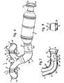
- Es zeigen, jeweils in schematischer Darstellung,
- Fig. 1
- eine Draufsicht auf eine erste Variante einer erfindungsgemäßen Abgasanlage,
- Fig. 2
- eine Ansicht eines Teils der Abgasanlage von
Fig. 1 in etwas vergrößerter Darstellung, - Fig. 3
- eine teilweise geschnittene Darstellung des Teils von
Fig. 2 , - Fig. 4
- eine teilweise geschnittene Darstellung eines anderen Teils der Abgasanlage von
Fig. 1 , - Fig. 5
- eine Ansicht in Richtung des Pfeils X in
Fig. 4 , - Fig. 6
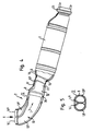
- eine Draufsicht auf eine nicht erfindungsgemäßen Abgasanlage,
- Fig. 7
- einen Schnitt gemäß Linie A - A in
Fig. 6 und - Fig. 8
- einen Schnitt durch einen Teil der Abgasanlage von
Fig. 6 . - Die in den
Figuren 1 bis 5 dargestellte Abgasanlage umfaßt ein erstes mit Abgasauslaßöffnungen eines Verbrennungsmotors zu verbindendes Modul 1, ein mit dem ersten Modul 1 verbundenes zweites Modul 2 und einen mit dem zweiten Modul 2 verbundenen Abgaskatalysator 3. Das erste Modul 1 umfaßt ein Gehäuse 4, welches eine Anordnung aus verzweigten Abgasrohren 5 aufnimmt. Wie man insbesondere in denFig. 2 und 3 erkennt, münden die verzweigten Abgasrohre 5 einerseits in sechs Abgaseintrittsöffnungen 6 und andererseits in zwei nebeneinanderliegenden Abgasaustrittsöffnungen 7. Die verzweigten Abgasrohre 5 umfassen dabei jeweils zwei Einzelrohre 5', 5" und 5''', die mit Schiebesitz in eines von zwei die Abgasaustrittsöffnungen 7 aufweisenden Sammelrohre 5IV eingesetzt sind, wobei die Sammelrohre 5IV im Bereich der Abgasaustrittsöffnungen 7 im Querschnitt D-förmig ausgebildet und mit ihrer abgeflachten Seite einander gegenüberliegend angeordnet sind. - Das Gehäuse 4 besteht aus zwei Blechhalbschalen 4' und 4", die miteinander verschweißt sind und die Anordnung aus verzweigten Abgasrohren 5 unter Bildung eines Luftspaltes 8 mit geringem Abstand umgeben. Das Gehäuse umfaßt außerdem drei Teile 4 a, b, c, die über zwei Wellbalge 9 miteinander verbunden sind.
- Im Bereich der Abgaseintrittsöffnungen 6 weist das Gehäuse 4 Befestigungsflansche 10 auf, die teilweise einer Abgaseintrittsöffnung 6, teilweise zwei Abgaseintrittsöffnungen 6 zugeordnet sind. Die Flansche 10 sind mit dem Gehäuse 4 durch Schweißen verbunden. Ebenso ist die Anordnung aus verzweigten Abgasrohren 5 im Bereich der Abgaseintrittsöffnungen 6 mit dem Gehäuse 4 verschweißt. Im übrigen sind die einzelnen Rohre 5' bis 5IV durch Schiebesitz miteinander verbunden.
- Die Flansche 10 sind im Bereich jeder Abgaseintrittsöffnung 6 mit zwei Schraubdurchführungen 11 versehen, mittels welcher die Abgasanlage an einem Verbrennungsmotor befestigbar ist. Wie man insbesondere in den
Fig. 1 und2 erkennt, sind das Gehäuse 4 und die verzweigten Abgasrohre 5 in einer zur Ebene der Flansche 10 parallelen Ebene derart wellenförmig gebogen ausgebildet, daß die Schraubdurchführungen 11 für einen senkrecht zu dieser Ebene gerichteten Zugriff freigehalten sind. Dementsprechend sind die beiden Schraubdurchführungen 11 im Bereich jeder Abgaseintrittsöffnung 6 abwechselnd in der einen und der anderen Richtung einander gegenüberliegend angeordnet. - Das zweite Modul 2 umfaßt ein Gehäuse 12 aus zwei Blechhalbschalen 12' und 12", in welchem, wie man insbesondere in den
Fig. 4 und 5 erkennt, eine Doppelrohranordnung 13 aus zwei parallel nebeneinander verlaufenden Abgasrohren 13' und 13" angeordnet ist. Die beiden Rohre 13' und 13" der Doppelrohranordnung sind im Querschnitt D-förmig ausgebildet und mit ihren abgeflachten Seiten 14', 14" einander gegenüberliegend angeordnet. Im Bereich ihrer Abgaseintrittsöffnungen 15' und 15" sind die beiden Abgasrohre 13' und 13" dabei im Querschnitt so ausgebildet, daß sie mit Schiebesitz mit den gasaustrittsseitigen Enden der beiden Sammelrohre 5IV verbindbar sind. - Mit ihrem anderen Ende sind die beiden Abgasrohre 13' und 13" der Doppelrohranordnung 13, ebenfalls mit Schiebesitz, in eine Strömungshülse 16 eingesetzt, die ebenfalls in dem Gehäuse 12 angeordnet ist. Die Strömungshülse 16 ist in Strömungsrichtung I verjüngt ausgebildet und weist in ihrem verjüngten Bereich 16' eine Aufnahme 17 für eine Lambdasonde auf. Mit ihrem gasaustrittsseitigen Ende 18 ist die Strömungshülse 16, wiederum mit Schiebesitz, in das Gehäuse 19 des Abgaskatalysators 3 eingesetzt.
- Alle Abgasrohre 5, 13 und 16 sind also innerhalb der Gehäuse 4, 12 schwimmend gelagert. Über Drahtgestrickringe 20 sind sie dabei in radialer Richtung relativ zu den die tragenden Teile darstellenden Gehäusen 4, 12 gehalten. Lediglich die Abgasrohre 5', 5" und 5''' der verzweigten Abgasrohranordnung 5 sind, wie bereits ausgeführt, abgaseintrittsseitig mit dem Gehäuse 4 durch Schweißen fest verbunden.
- An seinem gasaustrittsseitigem Ende weist der Abgaskatalysator 3 einen Flansch 21 zur Verbindung mit weiterführenden, hier nicht dargestellten Abgasrohren auf. Dabei sind bevorzugt keine weiteren Abgaskatalysatoren in dem Abgasstrang vorgesehen, das heißt das gesamte Katalysatorvolumen ist in dem einen Abgaskatalysator 3 untergebracht.
- Die Abgasaustrittsöffnungen 7 der Sammelrohre 5IV sind symmetrisch um die senkrecht zu der Verbindungslinie der Abgaseintrittsöffnungen 6 verlaufende Mittelebene II des Moduls 1 angeordnet. Auch die übrigen Elemente des ersten Moduls 1 sind bevorzugt in bezug auf diese Mittelebene II symmetrisch ausgebildet. Die Abgasrohre 5 und 13 sowie die Strömungshülse 16 sind bevorzugt durch Innenhochdruckumformen hergestellt.
- Bei der in den
Fig. 6 bis 8 dargestellten Variante umfaßt die Abgasanlage ebenfalls zwei Module 1 und 2 sowie einen Abgaskatalysator 3. Im Unterschied zu der ersten Variante ist das zweite Modul 2 jedoch zweiteilig ausgebildet, mit einem ersten Teil und einem zweiten Teil. Der erste Teil umfaßt die Doppelrohranordnung 13 und das diese umgebende Gehäuse 12', während der zweite Teil die Strömungshülse 16 und ein dieses umgebendes separates Gehäuse 12" umfaßt. Die beiden Gehäuse 12' und 12" sind durch Schweißen miteinander verbunden. - Ein weiterer Unterschied zu der ersten Variante besteht darin, daß die Anordnung aus verzweigten Abgasrohren 5 lediglich vier Abgaseintrittsöffnungen 6 aufweist. Die verzweigte Abgasrohranordnung 5 umfaßt zwei einfache, gebogene Abgasrohre 5', die mit Schiebesitz jeweils in eines von zwei verzweigten Abgasrohren 5V eingesetzt sind, deren anderer Zweig jeweils eine der Abgaseintrittsöffnungen 6 bildet und die anderenends die Abgasaustrittsöffnungen 7 der verzweigten Abgasrohranordnung 5 bilden.
- Wie in
Fig. 7 erkennbar, sind die beiden Rohre 13', 13" der Doppelrohranordnung 13 auch bei dieser Variante parallel angeordnet und münden abgasaustrittsseitig mit Schiebesitz in der Strömungshülse 16, die wiederum in einem verjüngten Abschnitt 16' eine Aufnahme 17 für die Lambdasonde aufweist. Auch die Strömungshülse 16 ist wiederum mit Schiebesitz in das Gehäuse 19 des Abgaskatalysators 3 eingesetzt, der bevorzugt das gesamte Katalysatorvolumen enthält. Auch hier ist also in diesem Abgasstrang kein weiterer Katalysator vorgesehen. - Wie man außerdem in
Fig. 7 erkennt, sind die beiden Rohre 13', 13" der Doppelrohranordnung 13 abgasaustrittsseitig bis kurz vor die Lambdasonde geführt. Dadurch wird im Bereich der Lambdasonde eine Mischzone 22 gebildet, in welcher die Abgasströmung mit Hilfe der Strömungshülse 16 neu gestaltet wird. Die Abgasströmung kann dadurch in gewünschter Weise ausgebildet werden, um die Anströmung des Katalysators 3 zu optimieren. Eine entsprechende Mischkammer 22 ist auch bei der ersten Variante vorhanden. - Wie man in den Figuren erkennt, ist das gesamte Katalysatorvolumen dadurch besonders motornah untergebracht. Dies verbessert die Katalysatorleistung. Durch die Verwendung von Modulen können die einzelnen Teile der Abgasanlage für verschiedene Einsatzzwecke verwendet werden. So kann das erste Modul 1 der ersten Variante aufgrund seiner symmetrischen Ausgestaltung in bezug auf die Mittelebene II sowohl für die linke als auch für die rechte Motorseite verwendet werden. Die zweiten Module 2 können grundsätzlich jeweils in Verbindung mit verschiedenen ersten Modulen 1 verwendet werden, beispielsweise wahlweise mit Modulen 1 mit vier oder sechs Abgaseintrittsöffnungen 6.
- Durch die Erfindung wird eine besonders kompakte Abgasanlage geschaffen, die mit einem Abgaskatalysator 3 auskommen kann. Dadurch kann das Katalysatorvolumen sehr nahe an den Motor herangebracht werden. In der als Mischkammer wirkenden Strömungshülse 16 kann der Abgasstrom geformt und dadurch eine optimale Anströmung des Abgaskatalysators 3 erreicht werden. Die lange Zweiflutigkeit durch die Doppelrohranordnung 13 hat zudem den Vorteil, daß sich die Abgasströme der Zylinder weniger gegenseitig beeinflussen können.
- Die erfindungsgemäße Abgasanlage ist außerdem, insbesondere aufgrund des modulartigen Aufbaus, günstig in der Herstellung und, insbesondere auch wegen der wellenförmigen Ausformung der Abgasrohre 5, in der Montage. Auch sind die Wärmespannungen im Gehäuse 4 aufgrund der wellenförmigen Ausgestaltung reduziert. Hierzu dienen auch die Wellbalge 9 zwischen den drei Teilen 4 a, b, c des Gehäuses 4.
-
- 1
- erstes Modul
- 2
- zweites Modul
- 3
- Abgaskatalysator
- 4
- Gehäuse
- 4', 4"
- Halbschale von 4
- 4 a, b, c
- Teile von 4
- 5
- verzweigte Abgasrohranordnung
- 5'-5V
- Abgasrohr
- 6
- Abgaseintrittsöffnung
- 7
- Abgasaustrittsöffnung
- 7', 7"
- Seite von 7
- 8
- Luftspalt
- 9
- Wellbalg
- 10
- Motorflansch
- 11
- Schraubendurchführung
- 12
- Gehäuse
- 12', 12"
- Teile von 12
- 13
- Doppelrohranordnung
- 13', 13"
- Abgasrohr von 13
- 14', 14"
- Seiten von 13', 13"
- 15', 15"
- Abgaseintrittsöffnung von 13', 13"
- 16
- Strömungshülse
- 16'
- Abschnitt von 16
- 17
- Lambdasondenaufnahme
- 18
- Ende von 16
- 19
- Gehäuse von 3
- 20
- Drahtgestrickring
- 21
- Flansch
- 22
- Mischzone
- I
- Abgasstromrichtung
- II
- Mittelebene
Claims (10)
- Abgasanlage für mehrzylindrige Verbrennungsmotoren mit einem Abgaskrümmer mit einer sich in Richtung auf den Motor verzweigenden, auf einer Motorseite an dessen Abgasauslassöffnungen anschließbaren Anordnung aus Abgasrohren (5) und mindestens einem Abgaskatalysator (3), wobei die Abgasaustrittsseite der verzweigten Abgasrohranordnung (5) durch zwei nebeneinanderliegende Gasaustrittsöffnungen (7) gebildet ist, mit denen jeweils ein Teil der verzweigten Abgasrohre (5) in Strömungsverbindung steht und an die jeweils ein Rohr (13', 13") einer Doppelrohranordnung (13) mit zwei parallel nebeneinander verlaufenden Rohren (13', 13") angeschlossen ist, deren anderes, gasaustrittsseitiges Ende in einer vor dem Abgaskatalysator (3) angeordneten Strömungshülse (16) mündet, in welcher die Katalysatoranströmung gestaltet wird,
dadurch gekennzeichnet,
dass die Lambdasonde (17) des Abgaskatalysators (3) in der Strömungshülse (16) angeordnet ist und dass die Doppelrohranordnung (13) in Bezug auf die zur Verbindungslinie der Abgaseintrittsöffnungen (6) senkrechte Mittelebene (II) des die verzweigte Abgasrohranordnung (5) umfassenden Moduls (1) mittig an die verzweigte Abgasrohranordnung (5) angeschlossen ist. - Abgasanlage für mehrzylindrige Verbrennungsmotoren nach Anspruch 1,
dadurch gekennzeichnet,
dass die Doppelrohranordnung (13) bis kurz vor die sogenannte Lambdasonde (17) des Abgaskatalysators (3) geführt ist. - Abgasanlage für mehrzylindrige Verbrennungsmotoren nach einem der vorhergehenden Ansprüche,
dadurch gekennzeichnet,
dass die Strömungshülse (16) zur Erzielung einer Düsenwirkung in Richtung auf den Abgaskatalysator (3) im Durchmesser verjüngt ausgebildet ist und/oder dass die Rohre (13', 13") der Doppelrohranordnung (13) im Querschnitt D-förmig ausgebildet und mit ihrer abgeflachten Seite (14', 14") einander zugewandt sind. - Abgasanlage für mehrzylindrige Verbrennungsmotoren nach einem der vorhergehenden Ansprüche,
dadurch gekennzeichnet,
dass die Rohre (13', 13") der Doppelrohranordnung (13) in einem gemeinsamen Gehäuse (12) angeordnet sind, wobei für die Doppelrohranordnung (13) und die Strömungshülse (16) bevorzugt ein gemeinsames Gehäuse (12) vorgesehen ist, und/oder dass die Rohre (5) der verzweigten Abgasrohranordnung in einem gemeinsamen Gehäuse (4) angeordnet sind. - Abgasanlage für mehrzylindrige Verbrennungsmotoren nach einem der vorhergehenden Ansprüche,
dadurch gekennzeichnet,
dass zumindest der überwiegende Teil des Katalysatorvolumens, insbesondere das gesamte Katalysatorvolumen, des Abgasstrangs in dem auf die Strömungshülse (16) folgenden Abgaskatalysator (3) angeordnet ist. - Abgasanlage für mehrzylindrige Verbrennungsmotoren nach einem der vorhergehenden Ansprüche,
dadurch gekennzeichnet,
dass die Abgasanlage modulartig aufgebaut ist, mit einem ersten, die verzweigte Abgasrohranordnung (5) umfassenden Modul (1) und einem zweiten, die Doppelrohranordnung (13) umfassenden Modul (2), wobei das erste Modul (1) bevorzugt zumindest hinsichtlich des Anschlusses für das zweite Modul (2) in Bezug auf seine senkrecht zu der Verbindungslinie der Abgaseintrittsöffnungen (6) verlaufende Mittelebene (II) symmetrisch ausgebildet ist, und/oder daß die Gehäuse (4, 12) als die tragenden Elemente ausgebildet sind, während die Abgasrohre (5, 13, 16) darin schwimmend gelagert und nur einseitig mit dem Gehäuse (4) fest verbunden, insbesondere verschweißt sind. - Abgasanlage für mehrzylindrige Verbrennungsmotoren nach einem der vorhergehenden Ansprüche,
dadurch gekennzeichnet,
dass die verzweigte Abgasrohranordnung (5) motorseitig mit ihrem Gehäuse (4) verbunden ist, während die Rohre (13', 13") der Doppelrohranordnung (13) mit der verzweigten Abgasrohranordnung (5) und der Strömungshülse (16) durch Schiebesitz verbunden sind und/oder dass das Gehäuse (4) der verzweigten Abgasrohranordnung (5) mit dem Gehäuse (12) der Doppelrohranordnung (13), dieses mit dem Gehäuse (21) der Strömungshülse (16) und diese wiederum mit dem Gehäuse (22) des Katalysators (3) fest verbunden, insbesondere verschweißt ist. - Abgasanlage nach einem der vorhergehenden Ansprüche,
dadurch gekennzeichnet,
dass die Abgasrohre (5) der verzweigten Abgasrohranordnung samt ihrem Gehäuse (4) in Draufsicht auf die Ebene der Abgaseintrittsöffnungen (6) einer Wellenlinie folgend derart abwechselnd nach oben und nach unten gebogen ausgebildet sind, daß neben den Abgaseintrittsöffnungen (6) Freiräume für den Zugang zu den Schraubdurchführungen (11) für die Befestigung der Abgasanlage am Motor gebildet sind. - Abgasanlage nach einem der vorhergehenden Ansprüche,
dadurch gekennzeichnet,
dass ein die verzweigte Abgasrohranordnung (5) umgebendes, fest mit dem Motor verbindbares Gehäuse (4) vorgesehen ist und dass das Gehäuse (4) mindestens einmal in Richtung der Verbindungslinie der Abgaseintrittsöffnungen (6) unterteilt ist, wobei die Teile (4 a, b, c) über flexible Elemente, insbesondere Wellbalge (9), miteinander verbunden sind. - Abgasanlage für mehrzylindrige Verbrennungsmotoren nach einem der vorhergehenden Ansprüche,
dadurch gekennzeichnet,
dass die Gehäuse (4, 12) jeweils aus Blech bestehen und zwei Halbschalen (4', 4"; 12', 12") umfassen und/oder daß die Abgasrohre (5, 13) durch Innenhochdruckumformung hergestellt sind und/oder dass die verzweigte Abgasrohranordnung (5) vier oder sechs Abgaseintrittsöffnungen (6) aufweist.
Applications Claiming Priority (2)
| Application Number | Priority Date | Filing Date | Title |
|---|---|---|---|
| DE10144015A DE10144015A1 (de) | 2001-09-07 | 2001-09-07 | Abgasanlage für mehrzylindrige Verbrennungsmotoren |
| DE10144015 | 2001-09-07 |
Publications (3)
| Publication Number | Publication Date |
|---|---|
| EP1291500A2 EP1291500A2 (de) | 2003-03-12 |
| EP1291500A3 EP1291500A3 (de) | 2005-10-05 |
| EP1291500B1 true EP1291500B1 (de) | 2008-04-16 |
Family
ID=7698136
Family Applications (1)
| Application Number | Title | Priority Date | Filing Date |
|---|---|---|---|
| EP02017485A Expired - Lifetime EP1291500B1 (de) | 2001-09-07 | 2002-08-05 | Abgasanlage für mehrzylindrige Verbrennungsmotoren |
Country Status (3)
| Country | Link |
|---|---|
| EP (1) | EP1291500B1 (de) |
| AT (1) | ATE392541T1 (de) |
| DE (2) | DE10144015A1 (de) |
Cited By (2)
| Publication number | Priority date | Publication date | Assignee | Title |
|---|---|---|---|---|
| DE102011084528A1 (de) * | 2011-10-14 | 2013-04-18 | Witzenmann Gmbh | Rohrleitungselement, insbesondere für die Abgasanlage eines Verbrennungsmotors |
| US10584627B2 (en) | 2015-09-22 | 2020-03-10 | Tenneco Gmbh | Manifold |
Families Citing this family (9)
| Publication number | Priority date | Publication date | Assignee | Title |
|---|---|---|---|---|
| DE20303759U1 (de) | 2003-03-10 | 2004-07-22 | Friedrich Boysen Gmbh & Co. Kg | Abgasanlage einer Brennkraftmaschine |
| DE102007062659A1 (de) | 2007-12-24 | 2009-06-25 | J. Eberspächer GmbH & Co. KG | Abgassammler und zugehöriges Herstellungsverfahren |
| DE102007062660A1 (de) | 2007-12-24 | 2009-06-25 | J. Eberspächer GmbH & Co. KG | Abgaskrümmer |
| DE102007062661A1 (de) * | 2007-12-24 | 2009-06-25 | J. Eberspächer GmbH & Co. KG | Abgassammler |
| DE102010060071A1 (de) | 2010-10-20 | 2012-05-10 | Dr. Ing. H.C. F. Porsche Aktiengesellschaft | Teil einer Abgasanlage für einen Verbrennungsmotor |
| JP5845777B2 (ja) | 2011-09-28 | 2016-01-20 | マツダ株式会社 | 多気筒エンジンの吸排気装置 |
| DE102014103804A1 (de) * | 2014-03-20 | 2015-09-24 | Tenneco Gmbh | Krümmer |
| JP6311539B2 (ja) * | 2014-09-01 | 2018-04-18 | マツダ株式会社 | 多気筒エンジンの排気装置 |
| CN105257382A (zh) * | 2015-10-21 | 2016-01-20 | 苏树杰 | 一种汽车尾气排气管 |
Family Cites Families (20)
| Publication number | Priority date | Publication date | Assignee | Title |
|---|---|---|---|---|
| JPS5031216A (de) * | 1973-07-18 | 1975-03-27 | ||
| JPS59103942A (ja) * | 1983-11-14 | 1984-06-15 | Hitachi Ltd | 排気通路装置 |
| DE3427998A1 (de) * | 1984-07-28 | 1986-01-30 | Witzenmann GmbH, Metallschlauch-Fabrik Pforzheim, 7530 Pforzheim | Abgasleitung fuer kraftfahrzeugmotoren |
| FR2586753A1 (fr) * | 1985-09-04 | 1987-03-06 | Peugeot Cycles | Dispositif de controle des gaz d'echappement d'un moteur a combustion interne |
| US4644747A (en) * | 1986-02-10 | 1987-02-24 | General Motors Corporation | Low-stress shielded exhaust passage assemblies |
| JPH055214Y2 (de) * | 1986-08-20 | 1993-02-10 | ||
| JPH0255823A (ja) * | 1988-08-17 | 1990-02-26 | Nippon Steel Corp | 排気マニホールド |
| JP2632601B2 (ja) * | 1991-02-18 | 1997-07-23 | 株式会社ユタカ技研 | 排気管 |
| US5331810A (en) * | 1992-05-21 | 1994-07-26 | Arvin Industries, Inc. | Low thermal capacitance exhaust system for an internal combustion engine |
| DE4228187C2 (de) * | 1992-08-25 | 1995-04-27 | Hde Metallwerk Gmbh | Abgaskrümmer für Verbrennungsmotoren |
| JPH06200755A (ja) * | 1992-12-28 | 1994-07-19 | Toyota Motor Corp | 車両用v型エンジンの排気マニホールド |
| DE4339290C2 (de) * | 1993-11-18 | 1995-11-02 | Daimler Benz Ag | Verfahren zum Herstellen von Rohr-T-Stücken aus einem unverzweigt durchgehenden Ausgangsrohrstück durch Innenhochdruck-Umformung sowie Vorrichtung zur Durchführung des Verfahrens |
| DE19524980A1 (de) * | 1995-07-08 | 1997-01-09 | Opel Adam Ag | Abgasanlage einer Mehrzylinder-Brennkraftmaschine |
| JPH108953A (ja) * | 1996-06-28 | 1998-01-13 | Nissan Motor Co Ltd | V型内燃機関の排気マニホルド |
| JP3378474B2 (ja) * | 1997-08-06 | 2003-02-17 | トヨタ自動車株式会社 | 内燃機関の排気マニホルド |
| DE19819946A1 (de) * | 1998-05-05 | 1999-11-11 | Boysen Friedrich Gmbh Co Kg | Abgaskrümmer |
| DE19858641A1 (de) * | 1998-12-18 | 2000-06-21 | Volkswagen Ag | Katalysator-Anordnung an einem Kraftfahrzeug |
| JP2000199427A (ja) * | 1998-12-28 | 2000-07-18 | Hitachi Metals Ltd | タ―ボチャ―ジャ用タ―ビンハウジングを鋳造一体化した排気マニホ―ルド |
| DE19923557B4 (de) * | 1999-05-21 | 2006-07-13 | Daimlerchrysler Ag | Gebauter luftspaltisolierter Abgaskrümmer einer Abgasanlage eines Kraftfahrzeuges und ein Verfahren zu dessen Herstellung |
| DE19945266C2 (de) * | 1999-09-21 | 2001-07-19 | Daimler Chrysler Ag | Abgasanlage |
-
2001
- 2001-09-07 DE DE10144015A patent/DE10144015A1/de not_active Withdrawn
-
2002
- 2002-08-05 EP EP02017485A patent/EP1291500B1/de not_active Expired - Lifetime
- 2002-08-05 DE DE50212097T patent/DE50212097D1/de not_active Expired - Lifetime
- 2002-08-05 AT AT02017485T patent/ATE392541T1/de not_active IP Right Cessation
Cited By (2)
| Publication number | Priority date | Publication date | Assignee | Title |
|---|---|---|---|---|
| DE102011084528A1 (de) * | 2011-10-14 | 2013-04-18 | Witzenmann Gmbh | Rohrleitungselement, insbesondere für die Abgasanlage eines Verbrennungsmotors |
| US10584627B2 (en) | 2015-09-22 | 2020-03-10 | Tenneco Gmbh | Manifold |
Also Published As
| Publication number | Publication date |
|---|---|
| DE10144015A1 (de) | 2003-03-27 |
| EP1291500A2 (de) | 2003-03-12 |
| EP1291500A3 (de) | 2005-10-05 |
| ATE392541T1 (de) | 2008-05-15 |
| DE50212097D1 (de) | 2008-05-29 |
Similar Documents
| Publication | Publication Date | Title |
|---|---|---|
| DE69935776T2 (de) | Mehrzylinderkopf | |
| EP2075430B1 (de) | Abgassammler | |
| EP2126294B1 (de) | Abgasnachbehandlungseinrichtung eines kraftfahrzeugs | |
| DE19522935A1 (de) | Modularer Katalysator und Auspuff für Verbrennungsmotor | |
| EP1009924B1 (de) | Katalysatorträgeranordnung für einen motornahen einbau | |
| EP0955453A2 (de) | Abgaskrümmer | |
| WO2001011209A1 (de) | Abgaskrümmer | |
| DE102007023545B4 (de) | Abgasanlage für einen V-Motor | |
| WO1999036681A1 (de) | Katalytischer konverter für einen schalldämpfer eines kleinmotors | |
| EP0835366B1 (de) | Katalysatoranordnung mit zwei- oder mehrsträngiger abgasführung | |
| DE4209155C2 (de) | Auspuffsystem für einen Verbrennungsmotor | |
| DE102009018104A1 (de) | Abgaskrümmer | |
| EP1291500A2 (de) | Abgasanlage für mehrzylindrige Verbrennungsmotoren | |
| DE69527928T2 (de) | Auspuffkrümmer | |
| EP1389267B1 (de) | Abgaskrümmer | |
| DE60014554T2 (de) | Katalysatoranordnung im Abgassystem einer mehrzylindrigen Brennkraftmaschine | |
| DE102007057755A1 (de) | Zylinderkopf und Abgassystem eines Mehrzylindermotors | |
| DE60018201T2 (de) | Vorrichtung zur selektiven kühlung von abgas eines kraftfahrzeugmotors | |
| DE69805326T2 (de) | Katalytischer konverter und verfahren zur montage eines konverters | |
| DE4038169C2 (de) | ||
| EP0192995B1 (de) | Abgasrohrkrümmer | |
| EP0753651A1 (de) | Abgasanlage einer Mehrzylinder-Brennkraftmaschine | |
| DE102019217853A1 (de) | Agr-kühler | |
| DE2613607A1 (de) | Mehrzylindermotor-auspuffsystem mit zwei separaten auspuffleitungen | |
| DE19755703A1 (de) | Katalysatorträgeranordnung für einen motornahen Einbau |
Legal Events
| Date | Code | Title | Description |
|---|---|---|---|
| PUAI | Public reference made under article 153(3) epc to a published international application that has entered the european phase |
Free format text: ORIGINAL CODE: 0009012 |
|
| AK | Designated contracting states |
Kind code of ref document: A2 Designated state(s): AT BE BG CH CY CZ DE DK EE ES FI FR GB GR IE IT LI LU MC NL PT SE SK TR Designated state(s): AT BE BG CH CY CZ DE DK EE ES FI FR GB GR IE IT LI LU MC NL PT SE SK TR |
|
| AX | Request for extension of the european patent |
Extension state: AL LT LV MK RO SI |
|
| PUAL | Search report despatched |
Free format text: ORIGINAL CODE: 0009013 |
|
| AK | Designated contracting states |
Kind code of ref document: A3 Designated state(s): AT BE BG CH CY CZ DE DK EE ES FI FR GB GR IE IT LI LU MC NL PT SE SK TR |
|
| AX | Request for extension of the european patent |
Extension state: AL LT LV MK RO SI |
|
| 17P | Request for examination filed |
Effective date: 20051124 |
|
| AKX | Designation fees paid |
Designated state(s): AT CZ DE FR GB IT |
|
| 17Q | First examination report despatched |
Effective date: 20060411 |
|
| 17Q | First examination report despatched |
Effective date: 20060411 |
|
| GRAP | Despatch of communication of intention to grant a patent |
Free format text: ORIGINAL CODE: EPIDOSNIGR1 |
|
| GRAS | Grant fee paid |
Free format text: ORIGINAL CODE: EPIDOSNIGR3 |
|
| GRAA | (expected) grant |
Free format text: ORIGINAL CODE: 0009210 |
|
| AK | Designated contracting states |
Kind code of ref document: B1 Designated state(s): AT CZ DE FR GB IT |
|
| REF | Corresponds to: |
Ref document number: 50212097 Country of ref document: DE Date of ref document: 20080529 Kind code of ref document: P |
|
| ET | Fr: translation filed | ||
| PLBE | No opposition filed within time limit |
Free format text: ORIGINAL CODE: 0009261 |
|
| STAA | Information on the status of an ep patent application or granted ep patent |
Free format text: STATUS: NO OPPOSITION FILED WITHIN TIME LIMIT |
|
| 26N | No opposition filed |
Effective date: 20090119 |
|
| PGFP | Annual fee paid to national office [announced via postgrant information from national office to epo] |
Ref country code: AT Payment date: 20090814 Year of fee payment: 8 Ref country code: CZ Payment date: 20090731 Year of fee payment: 8 Ref country code: GB Payment date: 20090827 Year of fee payment: 8 |
|
| PGFP | Annual fee paid to national office [announced via postgrant information from national office to epo] |
Ref country code: IT Payment date: 20090819 Year of fee payment: 8 |
|
| GBPC | Gb: european patent ceased through non-payment of renewal fee |
Effective date: 20100805 |
|
| REG | Reference to a national code |
Ref country code: FR Ref legal event code: ST Effective date: 20110502 |
|
| PG25 | Lapsed in a contracting state [announced via postgrant information from national office to epo] |
Ref country code: IT Free format text: LAPSE BECAUSE OF NON-PAYMENT OF DUE FEES Effective date: 20100805 Ref country code: AT Free format text: LAPSE BECAUSE OF NON-PAYMENT OF DUE FEES Effective date: 20100805 Ref country code: CZ Free format text: LAPSE BECAUSE OF NON-PAYMENT OF DUE FEES Effective date: 20100805 |
|
| PG25 | Lapsed in a contracting state [announced via postgrant information from national office to epo] |
Ref country code: FR Free format text: LAPSE BECAUSE OF NON-PAYMENT OF DUE FEES Effective date: 20100831 |
|
| PG25 | Lapsed in a contracting state [announced via postgrant information from national office to epo] |
Ref country code: GB Free format text: LAPSE BECAUSE OF NON-PAYMENT OF DUE FEES Effective date: 20100805 |
|
| PGFP | Annual fee paid to national office [announced via postgrant information from national office to epo] |
Ref country code: FR Payment date: 20090914 Year of fee payment: 8 |
|
| PGFP | Annual fee paid to national office [announced via postgrant information from national office to epo] |
Ref country code: DE Payment date: 20211028 Year of fee payment: 20 |
|
| REG | Reference to a national code |
Ref country code: DE Ref legal event code: R071 Ref document number: 50212097 Country of ref document: DE |