EP1291217A1 - Fahrzeugdach mit einem bewegbaren Deckelelement - Google Patents
Fahrzeugdach mit einem bewegbaren Deckelelement Download PDFInfo
- Publication number
- EP1291217A1 EP1291217A1 EP02019352A EP02019352A EP1291217A1 EP 1291217 A1 EP1291217 A1 EP 1291217A1 EP 02019352 A EP02019352 A EP 02019352A EP 02019352 A EP02019352 A EP 02019352A EP 1291217 A1 EP1291217 A1 EP 1291217A1
- Authority
- EP
- European Patent Office
- Prior art keywords
- roof
- vehicle
- vehicle roof
- guide rails
- roof according
- Prior art date
- Legal status (The legal status is an assumption and is not a legal conclusion. Google has not performed a legal analysis and makes no representation as to the accuracy of the status listed.)
- Granted
Links
- 239000006096 absorbing agent Substances 0.000 claims description 23
- 230000035939 shock Effects 0.000 claims description 23
- 238000013016 damping Methods 0.000 claims description 12
- 239000012530 fluid Substances 0.000 claims description 11
- 238000006073 displacement reaction Methods 0.000 claims description 8
- 230000006835 compression Effects 0.000 claims description 2
- 238000007906 compression Methods 0.000 claims description 2
- 239000007787 solid Substances 0.000 description 5
- 102100037010 Fidgetin Human genes 0.000 description 4
- 101000878296 Homo sapiens Fidgetin Proteins 0.000 description 4
- 229910000831 Steel Inorganic materials 0.000 description 1
- 230000015572 biosynthetic process Effects 0.000 description 1
- 230000001419 dependent effect Effects 0.000 description 1
- 230000001627 detrimental effect Effects 0.000 description 1
- 230000000694 effects Effects 0.000 description 1
- 210000003746 feather Anatomy 0.000 description 1
- 239000011521 glass Substances 0.000 description 1
- 239000010720 hydraulic oil Substances 0.000 description 1
- 238000000034 method Methods 0.000 description 1
- 239000010959 steel Substances 0.000 description 1
- 230000007704 transition Effects 0.000 description 1
Images


Classifications
-
- B—PERFORMING OPERATIONS; TRANSPORTING
- B60—VEHICLES IN GENERAL
- B60J—WINDOWS, WINDSCREENS, NON-FIXED ROOFS, DOORS, OR SIMILAR DEVICES FOR VEHICLES; REMOVABLE EXTERNAL PROTECTIVE COVERINGS SPECIALLY ADAPTED FOR VEHICLES
- B60J7/00—Non-fixed roofs; Roofs with movable panels, e.g. rotary sunroofs
- B60J7/02—Non-fixed roofs; Roofs with movable panels, e.g. rotary sunroofs of sliding type, e.g. comprising guide shoes
-
- B—PERFORMING OPERATIONS; TRANSPORTING
- B60—VEHICLES IN GENERAL
- B60J—WINDOWS, WINDSCREENS, NON-FIXED ROOFS, DOORS, OR SIMILAR DEVICES FOR VEHICLES; REMOVABLE EXTERNAL PROTECTIVE COVERINGS SPECIALLY ADAPTED FOR VEHICLES
- B60J7/00—Non-fixed roofs; Roofs with movable panels, e.g. rotary sunroofs
- B60J7/02—Non-fixed roofs; Roofs with movable panels, e.g. rotary sunroofs of sliding type, e.g. comprising guide shoes
- B60J7/04—Non-fixed roofs; Roofs with movable panels, e.g. rotary sunroofs of sliding type, e.g. comprising guide shoes with rigid plate-like element or elements, e.g. open roofs with harmonica-type folding rigid panels
Definitions
- the present invention relates to a vehicle roof with a fixed in one Roof surface provided roof opening and a lid member for closing and at least partially opening the roof opening, wherein on the Cover element sliding elements are hinged, which are laterally along the roof opening arranged guide rails are guided displaceably.
- a folding roof for vehicles is also known in which a trapezoidal roof opening are closed by means of a folding roof can, whose Faltspriegel about joints with sliding elements pivotally connected, arranged in along the roof opening, a Angle enclosing guide rails are performed.
- the solution shown here is suitable only for folding roofs and is not on roofs with movable solid cover elements transferable.
- DE 199 38 605 C1 describes a folding roof for a vehicle, in which in the front guide element, the so-called rooftop, a bearing arrangement is provided, which with respect to the vehicle transverse direction ensures a tolerance compensation.
- This object is characterized in a vehicle roof of the type mentioned by solved that the mutual nominal distance of the guide rails changes over the course of the guide rails in the vehicle longitudinal direction, and each of the sliding elements at its end facing the cover element a has substantially in the vehicle transverse direction extending journal, the displaceable in a provided in the cover element bearing bush intervenes.
- the mutual nominal distance of the guide rails i. the nominal size of the distance of the guide rails, by correspondingly stable Design the bearing pin several centimeters, so that the shape of the Cover element or the course of the guide rails in an optimal manner the shape of the roof or be adapted to the course of the roof edges can.
- the bearing bush which is the displaceably arranged therein journal receives, is arranged in the cover element itself, arise in the solution according to the invention no disadvantages in terms of height of the vehicle roof.
- the parallelogram-like lever arrangement in a to the plane of Cover element offset plane must be arranged, which not only the Height of the movable roof is increased, but also either the Lever mechanism is freely visible from the outside or the roof opening accordingly must be made small to the lever mechanism in the surrounding the roof opening Can hide roof area
- the inventive Solution the full width of the roof are exploited, and there are no moving Parts visible to the outside.
- the guide rails in the Level of the lid member may have any shape, which consist Common applications in that the guide rails at an angle are arranged to each other, as for example in a trapezoidal Roof would be appropriate, or that the guide rails parallel to the roof level are curved, for example, for a roof, which in a middle Range is wider in the vehicle longitudinal direction than in the front and rear Area or in the front and in the rear area is wider than in the middle area.
- the width of the fixed roof surface in the vehicle longitudinal direction may change and can guide rails parallel to the side roof edges be arranged.
- Such a vehicle roof is not only visually appealing, but moreover expedient, as the guide rails thus over its entire length as close as possible to the roof edges, i. the transition area between the actual roof area and the roof side walls, can be introduced so that on the one hand a possible realize large roof opening and on the other hand, the headspace or the Viewing area in the passenger area kept inside the vehicle becomes.
- the roof opening substantially be rectangular, but the guide rails adapted to the roof shape may be, for example, parallel to the roof edges.
- the width of the roof opening can also according to the width of the change solid roof surface in the vehicle longitudinal direction, for example, trapezoidal be, on the one hand, on the one hand a variety of design options and On the other hand, the size of the roof opening can be optimized.
- a spring element which biases the bearing journal relative to the cover element.
- a special low overall height of the cover element results when in this case the spring element is arranged in axial extension to the journal and on engages the axial end of the journal.
- the damping device may further comprise a damping device be provided to prevent unwanted movements of the lid member to prevent the solid roof surface.
- the damping device include at least one shock absorber, which is a sudden shift of the Counteracts bearing pin relative to the bearing bush. Is the trunnion / bearing bushing arrangements on both sides of the lid member respectively associated with a shock absorber, so are advantageously the opposite one another Shock absorbers coupled together.
- the shock absorbers each having a piston arranged in a chamber, the Chamber divided into two pressure chambers, wherein the pressure chambers each other opposite shock absorbers are coupled so that by transfer of Pressurized fluid between the pressure chambers, the pistons each two opposite each other Shock absorber simultaneously inward or outward with respect to Cover element to be relocated.
- the lid member is independent from its displacement position in the vehicle longitudinal direction always centered centered and secured against jerky displacements in the vehicle transverse direction, so as to preclude unwanted shaking or rattling of the cover member as otherwise from a vehicle roof overflowing wind and by cross joints when cornering z. B. caused by cobblestones could be, and to avoid fatigue fractures of the cover connection.
- the damping device can also be accomplished by the fact that the journal / bearing bushing arrangements on both sides of the cover element in each case a tension and compression stiff drive element is assigned, the so coupled to each other, that the movement of a drive element a causes corresponding movement of the other drive element.
- a tension and compression stiff drive element is assigned, the so coupled to each other, that the movement of a drive element a causes corresponding movement of the other drive element.
- the drive elements which are for example, racks or For example, to couple with pressure-resistant drive cable, to couple with each other a gear can be provided.
- By adjusting the smooth running the gear can be here the damping effect of the damping device to adjust.
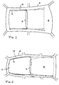
- FIG. 1 is denoted by 10 the solid roof of a vehicle roof, which in Direction of travel (to the left in Fig. 1 and 2) seen front narrower than the rear and accordingly forms an overall substantially trapezoidal surface.
- a roof opening 12 is formed by means of a displaceable in the vehicle longitudinal direction and under the fixed roof skin 10th Lowerable lid 14 either closed or largely released can be.
- the cover element 14 is in this case at the side along the roof opening 12 extending guide rails 16 out. As shown in FIG.
- the guide rails 16 extend over their entire Length parallel to the side roof frames or roof edges 18, so that the Headspace also in the rear of the passenger compartment below the widened Area of the roof surface free of required for guiding the lid member 14 Components can be kept, and in particular the headspace in this rear vehicle area not by straight guide rails, as seen from the State of the art are limited.
- the lid member 14 at least in its rear region of sliding elements stored, which (as with reference to Figures 3 to 5, in contrast to the internally guided cover 14 of FIGS.
- bearing journals which telescope in on the Cover element 14 provided bearing bushes are retracted and extended to the by shifting the cover element 14 in the vehicle longitudinal direction Distance between the bearing points of the lid member 14 and the guide rails 16 to bridge.
- FIG. Fig. 2 is another application example for the advantageous use of the here proposed vehicle roof presented.
- the roof surface 10 of a Vehicle which is for example a full-size sedan can act against a common design in its front area made narrower.
- a roof opening 12 is formed such that between the side edge of the roof opening 12 and the side Roof edge 18 remaining edge 19 of the fixed roof surface 10 a in the vehicle longitudinal direction has constant width.
- FIG. 3 shows a sectional view, seen in the vehicle transverse direction, in the region of Trailing edge of the lid member 14.
- the lid member 14 is in this case the rigid Cover of a sliding roof, which optionally under the fixed roof surface 10 can be lowered and moved backwards or its trailing edge can be issued beyond the fixed roof surface 10 addition.
- Near his trailing edge has the lid member 14, which is in particular to the Lid of a steel sunroof or the at least partially transparent Can cover a glass or plastic roof, a bearing assembly 20 provided with a designated at a total of 22 sliding member Journal 24 cooperates.
- the sliding member 22 are pivoted to the journal 24 and thus the Rear edge of the lid member 14 to raise, or it can be lowered in the State are moved along the guide rail 16.
- FIG. 4 shows a section through the vehicle roof from the FIGs. 1 or 2 in the area the guide rails, seen in the vehicle longitudinal direction.
- This clarifies the FIG. 4 shows the different positions of both the cover element 14, which in FIG FIG. 4 in the lowered position with 14 and in the raised position with 14 'and the trunnion / bushing assembly as follows is explained.
- the sliding element 22 a sliding block 26 which is guided in the guide rail 16.
- the sliding shoe 26 encloses the lower end of a support lever 28, on the upper End of the aligned in the vehicle transverse direction bearing pin 24 is attached.
- Of the Bearing 24 is guided in a bushing 30 telescopically displaceable, which is part of the mounted on the lid member 14 bearing assembly 20.
- FIG. 4 the support lever 28 both in his erected position in which the trailing edge of the lid member 14 over the fixed roof surface 10 is issued, as well as in the position when the cover element 14 is lowered.
- the bearing assembly 20 the rear of the Cover element 14 of the vehicle roof of FIG. 1, and is the Dekkelelement 14 fully extended, i. completely in the direction of travel to the rear shifted, so the support lever 28 takes in FIG. 4 position designated 28A in, in which the bearing pin 24 against the cover-fixed bearing bush 30th is extended.
- the lid member 14 for closing the Roof opening 12 completely shifted forward, so takes the support lever 28th the designated 28B position, in which the bearing pin 24 completely in the bearing bush 30 is retracted.
- the retraction and extension of the journal 24 with respect to the bushing 30 takes place forcibly by the shape of the Guide rails 16, which in the process of the cover member 14 to the rear the bearing pin 24 automatically pull outward from the bushings 30.
- the bushing 30 may be in two or more parts with in their longitudinal direction be formed corresponding spaced bearing guides, so that by reducing the bearing surfaces, the friction in the movement of the Bearing pin 24 is reduced.
- the individual bearing guides can be crowned be formed so that the storage is insensitive to tilting.
- FIG. 5 shows a view similar to FIG. 4, which has a journal / bushing arrangement illustrates how they in the front region of the lid member 14th of the in FIG. 2 shown vehicle roof is used.
- the lower end of the support lever 32nd is attached to a shoe 26 or is enclosed by the shoe 26, which is guided displaceably in the guide rail 16.
- the leading edge of the lid member 14 independently from the displacement position of the lid member 14 always on the same Height is maintained with respect to the guide rails 16 is a pivoting the support lever 32, as with reference to the FIGN. 3 and 4 for the Support lever 28 has been explained in the roof according to the FIG. 2 and 5 not required
- the pivoting of Stützhebebls 32 also on the Front edge of the lid member 14 may be provided.
- the cover member 14 is common with the journal / bushing assembly shown again, for simplicity the representation of the roof frame and the guide rail 16 omitted were.
- the sliding element 22 is in its maximum distance with respect to the lid member 14, wherein the bearing pin 24th maximum is pushed out of the bushing 30, so that the support lever occupies the position designated 32A.
- the location of the support lever 32 in the closed position of the lid member 14 is designated 32B. Is on the other hand differing from FIG. 2 the vehicle roof at the front wider than in his Middle, so the preceding sequence of movements is opposite.
- a spring element 35 is provided in the bearing arrangement 20, which biases the bearing pin 24 relative to the cover member 14 to the outside. To keep the height of the bearing assembly as low as possible, attacks the spring element 35 in this case to the inner end of the journal 24 in the axial extension of the journal 24. It is understood that the Formation of the spring element as a function of the desired requirements can also be done differently, for example by a journal 24 surrounding sleeve, with its inner end of the bearing pin 24th supported and from a bearing pin 24 surrounding spring to the outside is biased.
- FIG. Fig. 6 shows a preferred embodiment of a damping device, the jerky movements of the cover member 14 in the vehicle transverse direction prevented.
- separate shock absorbers one or more of the journals 24 can be provided is preferred that on both sides of the lid member 14 damping devices are provided, which are coupled together, as shown in the figures. 6 and 7 is shown.
- shock absorbers 34 are provided, which arranged one in a chamber 36 Have piston 38, the chamber 36 in two pressure chambers 40 and 42 divided.
- the plunger of the piston 38 is in this case with the bearing pin 24 of the Slider 22 is connected or formed by this.
- the pressure chambers 40 and 42 are with a suitable hydraulic fluid, in particular a hydraulic oil or with gas, filled.
- the pressure chambers of the two over the vehicle longitudinal axis away opposite shock absorbers 34 are hereby means Pressure fluid lines 44 and 46 coupled together, that in each case the internal Pressure chamber 40 of a shock absorber 34 with the outside Pressure chamber 42 of the other shock absorber is connected. Is it?
- the inertia of the system and thus the ability to damp jerky displacements of the cover member 14 in the vehicle transverse direction or to prevent this is due to the toughness of the pressurized fluid as well from the flow resistances of the pressure lines 44 and 46 and their inlets determined in the pressure chambers 40 and 42.
- the inertia causes of the pressurized fluid within the system that the lid member 14 also at suddenly acting on the vehicle roof forces, such as by a stream of air flowing over the vehicle roof or by road bumps can be caused, a stable position in the vehicle transverse direction maintains.
- FIG. Figure 7 shows an alternative embodiment for designing a coupled one Damping device.
- the bearing pin 24 of the sliding elements 22nd each rack 50 and 52 articulated whose from the sliding elements 22nd pioneering ends on a gear 48 attack so that a rotation of the Gear in FIG. 7 clockwise causes the journals 24 on both Sides of the lid member 14 are displaced inwardly, i. retracted while a rotation of the gear in FIG. 7 counterclockwise an extension of the two bearing pin 24 causes.
- the racks 50 and 52 and other traction and pressure resistant drive means may be provided, e.g. Pressure-resistant drive cable, as with the roofs described herein also for moving the lid member 14 are used.
Landscapes
- Engineering & Computer Science (AREA)
- Mechanical Engineering (AREA)
- Body Structure For Vehicles (AREA)
- Fittings On The Vehicle Exterior For Carrying Loads, And Devices For Holding Or Mounting Articles (AREA)
Abstract
Description
- FIG. 1
- ein Fahrzeug mit einem Fahrzeugdach nach der vorliegenden Erfindung;
- FIG. 2
- eine weitere Ausführungsform eines Fahrzeugdaches nach der vorliegenden Erfindung;
- FIG. 3
- eine Seitenansicht eines Gleitelements, wie es in den Dächern aus den FIGN. 1 und 2 eingesetzt wird;
- FIG. 4
- eine Schnittansicht durch eine der Führungsschienen, wie sie bei den Fahrzeugdächern gemäß den FIGN. 1 und 2 verwendet werden;
- FIG. 5
- eine Ansicht ähnlich FIG. 3 einer weiteren Ausführungsform des erfindungsgemäßen Fahrzeugdaches;
- FIG. 6
- eine schematische Schnittansicht einer Dämpfungseinrichtung des Fahrzeugdaches nach der vorliegenden Erfindung; und
- FIG. 7
- eine schematische Schnittansicht einer weiteren Ausführungsform einer Dämpfungseinrichtung für ein Fahrzeugdach nach der vorliegenden Erfindung.
- 10
- feste Dachhaut
- 12
- Dachöffnung
- 14
- Deckelelement
- 16
- Führungsschiene
- 18
- seitliche Dachkante
- 19
- Rand
- 20
- Lageranordnung an 14
- 22
- Gleitelement
- 24
- Lagerzapfen
- 26
- Gleitschuh
- 28
- Stützhebel
- 30
- Lagerbuchse
- 32
- Stützhebel
- 34
- Stoßdämpfer
- 35
- Feder
- 36
- Kammer
- 38
- Kolben
- 40, 42
- Druckkammern
- 44, 46
- Druckfluidleitungen
- 48
- Zahnrad
- 50, 52
- Zahnstangen
- 54
- Schwenkachse
Claims (17)
- Fahrzeugdach mit einer in einer festen Dachfläche (10) vorgesehenen Dachöffnung (12) und einem Deckelelement (14) zum Verschließen und wenigstens teilweisen Öffnen der Dachöffnung (12), wobei an dem Deckelelement (14) Gleitelemente (22) angelenkt sind, die in seitlich entlang der Dachöffnung (12) angeordneten Führungsschienen (16) verschiebbar geführt sind,
dadurch gekennzeichnet, dass die Führungsschienen (16) so angeordnet sind, dass sich der gegenseitige Nennabstand der Führungsschienen (16) über den Verlauf der Führungsschienen (16) in Fahrzeuglängsrichtung ändert, und
dass jedes der Gleitelemente (22) an seinem dem Deckelelement (14) zugewandten Ende einen sich im wesentlichen in Fahrzeugquerrichtung erstreckenden Lagerzapfen (24) aufweist, der in eine an dem Deckelelement (14) vorgesehene Lagerbuchse (30) verschiebbar eingreift. - Fahrzeugdach nach Anspruch 1,
dadurch gekennzeichnet, dass die Führungsschienen (16) unter einem Winkel zueinander angeordnet sind. - Fahrzeugdach nach Anspruch 1,
dadurch gekennzeichnet, dass die Führungsschienen (16) parallel zur Dachebene gekrümmt sind. - Fahrzeugdach nach einem der vorhergehenden Ansprüche,
dadurch gekennzeichnet, dass sich die Breite der festen Dachfläche (10) in Fahrzeuglängsrichtung ändert und die Führungsschienen (16) parallel zu den seitlichen Dachrahmen oder Dachkanten (18) angeordnet sind. - Fahrzeugdach nach Anspruch 4,
dadurch gekennzeichnet, dass sich die Breite der Dachöffnung (12) entsprechend der Breite der festen Dachfläche (10) in Fahrzeuglängsrichtung ändert. - Fahrzeugdach nach Anspruch 5,
dadurch gekennzeichnet, dass die Dachöffnung (12) im wesentlichen trapezförmig ist. - Fahrzeugdach nach einem der vorhergehenden Ansprüche,
dadurch gekennzeichnet, dass die Gleitelemente (22) schwenkbar gelagert sind. - Fahrzeugdach nach einem der vorhergehenden Ansprüche,
dadurch gekennzeichnet, dass in der Lagerbuchse (30) ein Federelement (35) vorgesehen ist, das den Lagerzapfen (24) gegenüber dem Deckelelement (14) vorspannt. - Fahrzeugdach nach Anspruch 8,
dadurch gekennzeichnet, dass das Federelement (35) in axialer Verlängerung zu dem Lagerzapfen (24) angeordnet ist und an das axiale Ende des Lagerzapfens (24) angreift. - Fahrzeugdach nach einem der vorhergehenden Ansprüche,
dadurch gekennzeichnet, dass eine Dämpfungseinrichtung (34) vorgesehen ist, um ungewollte Querbewegungen des Deckelelements (14) gegenüber der festen Dachfläche (10) zu verhindern. - Fahrzeugdach nach Anspruch 10,
dadurch gekennzeichnet, dass die Dämpfungseinrichtung mindestens einen Stoßdämpfer (34) umfasst, der einer plötzlichen Verlagerung des Lagerzapfens (24) gegenüber der Lagerbuchse (30) entgegenwirkt. - Fahrzeugdach nach Anspruch 11,
dadurch gekennzeichnet, dass den Lagerzapfen/Lagerbuchsen-Anordnungen (24, 30) zu beiden Seiten des Deckelelements (14) jeweils ein Stoßdämpfer (34) zugeordnet ist, und dass die einander gegenüber liegenden Stoßdämpfer miteinander gekoppelt sind. - Fahrzeugdach nach Anspruch 12,
dadurch gekennzeichnet, dass die Stoßdämpfer (34) jeweils einen in einer Kammer (36) angeordneten Kolben (38) aufweisen, der die Kammer (36) in zwei Druckkammern (40, 42) unterteilt, und dass die Druckkammern (40, 42) einander gegenüber liegender Stoßdämpfer (34) so gekoppelt sind, dass durch Überleitung von Druckfluid zwischen den Druckkammern (40, 42) die Kolben (38) jeweils zweier einander gegenüber liegender Stoßdämpfer (34) gleichzeitig einwärts bzw. auswärts bezüglich des Deckelelements (14) verlagert werden. - Fahrzeugdach nach Anspruch 10,
dadurch gekennzeichnet, dass den Lagerzapfen/Lagerbuchsen-Anordnungen (24, 30) zu beiden Seiten des Deckelelements (14) jeweils ein zug- und drucksteifes Antriebselement (50, 52) zugeordnet ist, die so miteinander gekoppelt sind, dass die Bewegung des einen Antriebselements eine entsprechende Bewegung des jeweils anderen Antriebselements hervorruft. - Fahrzeugdach nach Anspruch 14,
dadurch gekennzeichnet, dass die Antriebselemente (50, 52) über ein Zahnrad (48) miteinander gekoppelt sind und dass als Antriebselemente Zahnstangen (50, 52) oder drucksteife Antriebskabel vorgesehen sind. - Fahrzeugdach nach einem der vorhergehenden Ansprüche,
dadurch gekennzeichnet, dass die Gleitelemente (22) schwenkbar in den Führungsschienen (16) gelagert sind, um den Lagerzapfen (24) gegenüber der Führungsschiene (16) anzuheben. - Fahrzeugdach nach einem der vorhergehenden Ansprüche,
dadurch gekennzeichnet, dass der Lagerzapfen (24) um eine zum Deckelelement (14) senkrechte Schwenkachse (54) schwenkbar gelagert ist, insbesondere mittels seiner an dem Deckelelement (14) schwenkbar gelagerten Lagerbuchse (30).
Applications Claiming Priority (2)
| Application Number | Priority Date | Filing Date | Title |
|---|---|---|---|
| DE2001143838 DE10143838A1 (de) | 2001-09-06 | 2001-09-06 | Fahrzeugdach |
| DE10143838 | 2001-09-06 |
Publications (2)
| Publication Number | Publication Date |
|---|---|
| EP1291217A1 true EP1291217A1 (de) | 2003-03-12 |
| EP1291217B1 EP1291217B1 (de) | 2009-10-07 |
Family
ID=7698008
Family Applications (1)
| Application Number | Title | Priority Date | Filing Date |
|---|---|---|---|
| EP20020019352 Expired - Lifetime EP1291217B1 (de) | 2001-09-06 | 2002-08-29 | Fahrzeugdach mit einem bewegbaren Deckelelement |
Country Status (3)
| Country | Link |
|---|---|
| EP (1) | EP1291217B1 (de) |
| JP (1) | JP2003080947A (de) |
| DE (2) | DE10143838A1 (de) |
Cited By (9)
| Publication number | Priority date | Publication date | Assignee | Title |
|---|---|---|---|---|
| EP1419918A1 (de) | 2002-11-15 | 2004-05-19 | ArvinMeritor GmbH | Schiebedachsystem für ein Kraftfahrzeug |
| EP1577136A2 (de) | 2004-03-15 | 2005-09-21 | ArvinMeritor GmbH | Schiebedachsystem |
| EP1647430A3 (de) * | 2004-10-15 | 2007-01-17 | Dr.Ing. h.c.F. Porsche Aktiengesellschaft | Dachanordnung für ein Fahrzeug |
| EP1650068A3 (de) * | 2004-10-19 | 2009-11-04 | ArvinMeritor GmbH | Deckel für ein Schiebedachsystem |
| CN102781696A (zh) * | 2010-03-26 | 2012-11-14 | 韦巴斯托股份公司 | 具有聚碳酸酯盖的车顶 |
| EP2578427A1 (de) * | 2011-10-06 | 2013-04-10 | Inalfa Roof Systems Group B.V. | Dachanordnung für ein Fahrzeug |
| CN103158513A (zh) * | 2011-12-19 | 2013-06-19 | 银娜珐天窗系统集团股份有限公司 | 车辆的天窗结构 |
| US9827837B2 (en) * | 2016-03-31 | 2017-11-28 | Tesla, Inc. | Moveable panel system for non-parallel tracks |
| CN113954608A (zh) * | 2021-11-30 | 2022-01-21 | 上汽通用汽车有限公司 | 一种天窗总成及汽车 |
Families Citing this family (8)
| Publication number | Priority date | Publication date | Assignee | Title |
|---|---|---|---|---|
| DE10201636C5 (de) * | 2002-01-17 | 2010-04-08 | Webasto Ag | Schiebedachanordnung für ein Fahrzeug |
| DE20321666U1 (de) * | 2003-12-19 | 2008-09-11 | GM Global Technology Operations, Inc., Detroit | Beschattungssystem mit starren Beschattungselementen für eine Panoramascheibe eines Kraftfahrzeuges |
| FR2909594B1 (fr) * | 2006-12-06 | 2011-06-10 | Wagon Sas | Pavillon vitre de vehicule automobile,procede de montage et vehicule correspondants |
| DE102007059866A1 (de) * | 2007-12-12 | 2009-06-18 | Bayerische Motoren Werke Aktiengesellschaft | Schiebehebedach für ein Kraftfahrzeug |
| DE102008006285B3 (de) * | 2008-01-27 | 2009-06-25 | Webasto Ag | Fahrzeugdach mit einem längs zweier Führungsschienen mit sich veränderndem Abstand bewegbaren Dachteil |
| EP2380763B1 (de) * | 2010-04-20 | 2013-06-12 | Inalfa Roof Systems Group B.V. | Offene Dachkonstruktion für ein Fahrzeug |
| JP6569483B2 (ja) * | 2015-11-06 | 2019-09-04 | アイシン精機株式会社 | サンルーフ装置 |
| DE202016104017U1 (de) * | 2016-07-22 | 2017-10-26 | Inalfa Roof Systems Group B.V. | Offendachkonstruktion für ein Fahrzeug |
Citations (5)
| Publication number | Priority date | Publication date | Assignee | Title |
|---|---|---|---|---|
| US4995667A (en) * | 1988-03-03 | 1991-02-26 | Honda Giken Kogyo Kabushiki Kaisha | Vehicle sliding roof system |
| DE4306451C1 (de) | 1993-03-02 | 1994-03-31 | Webasto Karosseriesysteme | Faltdach eines Fahrzeuges |
| US5791728A (en) * | 1993-09-08 | 1998-08-11 | Hs Products Ag, Systemtechnik Und Produktmanagement | Guide mechanism for the cover plate of a vehicle sunroof |
| DE10002457A1 (de) * | 2000-01-21 | 2000-08-17 | Audi Ag | Schiebedach |
| DE19938605C1 (de) | 1999-08-14 | 2000-10-05 | Webasto Dachsysteme Gmbh | Fahrzeugdach mit einem verschiebbaren starren Element |
-
2001
- 2001-09-06 DE DE2001143838 patent/DE10143838A1/de not_active Ceased
-
2002
- 2002-08-29 EP EP20020019352 patent/EP1291217B1/de not_active Expired - Lifetime
- 2002-08-29 JP JP2002251672A patent/JP2003080947A/ja active Pending
- 2002-08-29 DE DE50213896T patent/DE50213896D1/de not_active Expired - Lifetime
Patent Citations (6)
| Publication number | Priority date | Publication date | Assignee | Title |
|---|---|---|---|---|
| US4995667A (en) * | 1988-03-03 | 1991-02-26 | Honda Giken Kogyo Kabushiki Kaisha | Vehicle sliding roof system |
| DE4306451C1 (de) | 1993-03-02 | 1994-03-31 | Webasto Karosseriesysteme | Faltdach eines Fahrzeuges |
| US5791728A (en) * | 1993-09-08 | 1998-08-11 | Hs Products Ag, Systemtechnik Und Produktmanagement | Guide mechanism for the cover plate of a vehicle sunroof |
| DE19938605C1 (de) | 1999-08-14 | 2000-10-05 | Webasto Dachsysteme Gmbh | Fahrzeugdach mit einem verschiebbaren starren Element |
| DE10002457A1 (de) * | 2000-01-21 | 2000-08-17 | Audi Ag | Schiebedach |
| DE10002457C2 (de) | 2000-01-21 | 2001-03-08 | Audi Ag | Schiebedach |
Cited By (15)
| Publication number | Priority date | Publication date | Assignee | Title |
|---|---|---|---|---|
| EP1419918A1 (de) | 2002-11-15 | 2004-05-19 | ArvinMeritor GmbH | Schiebedachsystem für ein Kraftfahrzeug |
| EP1577136A2 (de) | 2004-03-15 | 2005-09-21 | ArvinMeritor GmbH | Schiebedachsystem |
| EP1577136A3 (de) * | 2004-03-15 | 2007-05-30 | ArvinMeritor GmbH | Schiebedachsystem |
| EP1647430A3 (de) * | 2004-10-15 | 2007-01-17 | Dr.Ing. h.c.F. Porsche Aktiengesellschaft | Dachanordnung für ein Fahrzeug |
| US7258397B2 (en) | 2004-10-15 | 2007-08-21 | Dr. Ing. H.C.F. Porsche Aktiengesellschaft | Roof arrangement for a vehicle |
| EP1650068A3 (de) * | 2004-10-19 | 2009-11-04 | ArvinMeritor GmbH | Deckel für ein Schiebedachsystem |
| CN102781696A (zh) * | 2010-03-26 | 2012-11-14 | 韦巴斯托股份公司 | 具有聚碳酸酯盖的车顶 |
| EP2578427A1 (de) * | 2011-10-06 | 2013-04-10 | Inalfa Roof Systems Group B.V. | Dachanordnung für ein Fahrzeug |
| CN103072454A (zh) * | 2011-10-06 | 2013-05-01 | 银娜珐天窗系统集团股份有限公司 | 用于车辆的车顶组件 |
| US8757710B2 (en) | 2011-10-06 | 2014-06-24 | Inalfa Roof Systems Group B.V. | Roof assembly for a vehicle |
| CN103072454B (zh) * | 2011-10-06 | 2016-11-23 | 英纳法天窗系统集团有限公司 | 用于车辆的车顶组件 |
| CN103158513A (zh) * | 2011-12-19 | 2013-06-19 | 银娜珐天窗系统集团股份有限公司 | 车辆的天窗结构 |
| CN103158513B (zh) * | 2011-12-19 | 2016-05-18 | 英纳法天窗系统集团有限公司 | 车辆的天窗结构 |
| US9827837B2 (en) * | 2016-03-31 | 2017-11-28 | Tesla, Inc. | Moveable panel system for non-parallel tracks |
| CN113954608A (zh) * | 2021-11-30 | 2022-01-21 | 上汽通用汽车有限公司 | 一种天窗总成及汽车 |
Also Published As
| Publication number | Publication date |
|---|---|
| DE10143838A1 (de) | 2003-03-27 |
| DE50213896D1 (de) | 2009-11-19 |
| JP2003080947A (ja) | 2003-03-19 |
| EP1291217B1 (de) | 2009-10-07 |
Similar Documents
| Publication | Publication Date | Title |
|---|---|---|
| EP1291217B1 (de) | Fahrzeugdach mit einem bewegbaren Deckelelement | |
| EP1074415B1 (de) | Cabriolet-Fahrzeug | |
| EP1364823A1 (de) | Cabriolet-Fahrzeug mit einem unterhalb eines Deckelteils ablegbaren Dach | |
| EP2899089B1 (de) | Schwenkschiebetürmodul für ein Schienenfahrzeug mit mehreren über einen Bowdenzug gekoppelten Übertotpunktverriegelungen | |
| DE102018202386A1 (de) | Fahrzeug mit einer Fahrzeugkarosserie und zumindest einer Fahrzeugtür | |
| DE10213548B4 (de) | Cabriolet-Fahrzeug mit Beladeerleichterung | |
| DE3305758C2 (de) | Knickschutzsteuerung | |
| EP1254799A2 (de) | Öffnungsfähiges Fahrzeugdach | |
| EP3148826B1 (de) | Anordnung mit einem deckel für ein fahrzeugdach | |
| DE102004003956B4 (de) | Heckklappe eines Kraftfahrzeugs | |
| DE10143823A1 (de) | Fahrzeugdach | |
| DE102005042017A1 (de) | Dachkonstruktion für Kraftfahrzeuge | |
| DE10140433A1 (de) | Verdeck für ein Kraftfahrzeug | |
| EP2004432A1 (de) | Hardtop-klappverdeck für einen offenen kraftwagen | |
| DE102008006285B3 (de) | Fahrzeugdach mit einem längs zweier Führungsschienen mit sich veränderndem Abstand bewegbaren Dachteil | |
| DE102008061395B4 (de) | Kraftfahrzeug mit Mechanismus zum Bewegen einer Klappe oder Scherentüre | |
| DE102006061489B4 (de) | Heckdeckel für einen Aufbau eines Kraftfahrzeugs | |
| DE102024115272B3 (de) | Öffnungsfähiges Fahrzeugdach mit einem verlagerbaren Deckel | |
| EP1848603B1 (de) | Hardtop-verdeck | |
| DE102004011903B4 (de) | Vorrichtung zum Führen einer ausschwenkbaren Schiebetür an einer Fahrzeugkarosserie | |
| DE102008006284B4 (de) | Fahrzeugdach mit einem bewegbaren Dachteil | |
| DE102004039134B4 (de) | Hardtop-Verdeck für ein Cabriolet-Fahrzeug | |
| DE102005028991B4 (de) | Lenkeranordnung für ein Fahrzeugdach | |
| DE102004048142A1 (de) | Hardtop-Verdeck | |
| DE102005050897B3 (de) | Hardtop-Fahrzeugdach mit mindestens einem starren Dachteil |
Legal Events
| Date | Code | Title | Description |
|---|---|---|---|
| PUAI | Public reference made under article 153(3) epc to a published international application that has entered the european phase |
Free format text: ORIGINAL CODE: 0009012 |
|
| AK | Designated contracting states |
Designated state(s): AT BE BG CH CY CZ DE DK EE ES FI FR GB GR IE IT LI LU MC NL PT SE SK TR Kind code of ref document: A1 Designated state(s): AT BE BG CH CY CZ DE DK EE ES FI FR GB GR IE IT LI LU MC NL PT SE SK TR |
|
| AX | Request for extension of the european patent |
Extension state: AL LT LV MK RO SI |
|
| 17P | Request for examination filed |
Effective date: 20030828 |
|
| AKX | Designation fees paid |
Designated state(s): DE FR GB NL |
|
| 17Q | First examination report despatched |
Effective date: 20080715 |
|
| RAP1 | Party data changed (applicant data changed or rights of an application transferred) |
Owner name: WEBASTO AG |
|
| GRAP | Despatch of communication of intention to grant a patent |
Free format text: ORIGINAL CODE: EPIDOSNIGR1 |
|
| GRAS | Grant fee paid |
Free format text: ORIGINAL CODE: EPIDOSNIGR3 |
|
| GRAA | (expected) grant |
Free format text: ORIGINAL CODE: 0009210 |
|
| AK | Designated contracting states |
Kind code of ref document: B1 Designated state(s): DE FR GB NL |
|
| REG | Reference to a national code |
Ref country code: GB Ref legal event code: FG4D Free format text: NOT ENGLISH |
|
| REF | Corresponds to: |
Ref document number: 50213896 Country of ref document: DE Date of ref document: 20091119 Kind code of ref document: P |
|
| NLV1 | Nl: lapsed or annulled due to failure to fulfill the requirements of art. 29p and 29m of the patents act | ||
| PG25 | Lapsed in a contracting state [announced via postgrant information from national office to epo] |
Ref country code: NL Free format text: LAPSE BECAUSE OF FAILURE TO SUBMIT A TRANSLATION OF THE DESCRIPTION OR TO PAY THE FEE WITHIN THE PRESCRIBED TIME-LIMIT Effective date: 20091007 |
|
| PLBE | No opposition filed within time limit |
Free format text: ORIGINAL CODE: 0009261 |
|
| STAA | Information on the status of an ep patent application or granted ep patent |
Free format text: STATUS: NO OPPOSITION FILED WITHIN TIME LIMIT |
|
| 26N | No opposition filed |
Effective date: 20100708 |
|
| GBPC | Gb: european patent ceased through non-payment of renewal fee |
Effective date: 20100829 |
|
| REG | Reference to a national code |
Ref country code: FR Ref legal event code: ST Effective date: 20110502 |
|
| PG25 | Lapsed in a contracting state [announced via postgrant information from national office to epo] |
Ref country code: FR Free format text: LAPSE BECAUSE OF NON-PAYMENT OF DUE FEES Effective date: 20100831 |
|
| PG25 | Lapsed in a contracting state [announced via postgrant information from national office to epo] |
Ref country code: GB Free format text: LAPSE BECAUSE OF NON-PAYMENT OF DUE FEES Effective date: 20100829 |
|
| PGFP | Annual fee paid to national office [announced via postgrant information from national office to epo] |
Ref country code: DE Payment date: 20190822 Year of fee payment: 18 |
|
| REG | Reference to a national code |
Ref country code: DE Ref legal event code: R119 Ref document number: 50213896 Country of ref document: DE |
|
| PG25 | Lapsed in a contracting state [announced via postgrant information from national office to epo] |
Ref country code: DE Free format text: LAPSE BECAUSE OF NON-PAYMENT OF DUE FEES Effective date: 20210302 |