EP1291216A1 - Rahmen für ein Fahrzeug-Schiebedach oder -Schiebehebedach - Google Patents
Rahmen für ein Fahrzeug-Schiebedach oder -Schiebehebedach Download PDFInfo
- Publication number
- EP1291216A1 EP1291216A1 EP02014684A EP02014684A EP1291216A1 EP 1291216 A1 EP1291216 A1 EP 1291216A1 EP 02014684 A EP02014684 A EP 02014684A EP 02014684 A EP02014684 A EP 02014684A EP 1291216 A1 EP1291216 A1 EP 1291216A1
- Authority
- EP
- European Patent Office
- Prior art keywords
- side parts
- guide
- frame according
- guide tubes
- front part
- Prior art date
- Legal status (The legal status is an assumption and is not a legal conclusion. Google has not performed a legal analysis and makes no representation as to the accuracy of the status listed.)
- Granted
Links
Images


Classifications
-
- B—PERFORMING OPERATIONS; TRANSPORTING
- B60—VEHICLES IN GENERAL
- B60J—WINDOWS, WINDSCREENS, NON-FIXED ROOFS, DOORS, OR SIMILAR DEVICES FOR VEHICLES; REMOVABLE EXTERNAL PROTECTIVE COVERINGS SPECIALLY ADAPTED FOR VEHICLES
- B60J7/00—Non-fixed roofs; Roofs with movable panels, e.g. rotary sunroofs
- B60J7/02—Non-fixed roofs; Roofs with movable panels, e.g. rotary sunroofs of sliding type, e.g. comprising guide shoes
- B60J7/022—Sliding roof trays or assemblies
Definitions
- the invention relates to a frame for a vehicle sunroof or sliding sunroof, according to the generic term of claim 1.
- Such a known frame (DE 40 14 487 C1) is to the Joints between the corner areas of the front part and the side parts formed so that the ends of the guide tubes protrude beyond the corner areas of the front part and can be inserted into the cable duct in the side panels are.
- This is intended to connect the front part during assembly and side parts the required torsional rigidity and dimensional accuracy can be achieved so that these protruding guide tube ends as assembly aids for assembling and aligning the longitudinal parts and the front part serve the frame. It is also said to be a smoother Transition between the protruding ends of the guide tubes and the guide channels in the side panels his.
- the invention has for its object a framework provide training specified in the beginning, in which at the transition points between the guide tubes of the front part and the guide channels of the side parts no noise arise and no engine vibrations are transmitted can.
- the plastic fasteners can be used as separate Parts should be formed on the one hand with the corner areas of the front part and on the other hand with the side parts, for example by means of clip connections in a positioned position are firmly connectable, preferably the connecting elements however an integral part of the corner areas themselves, as stated in claim 2.
- the ends of the guide tubes are a continuation of the inventive concept according to claim 3 within the corner areas overmoulded with plastic, one on each guide tube the distance to the associated guide channel in the side part bridging cavity in alignment in the connecting element connected.
- the ends the guide tubes and, according to claim 7, the inlet ends the cable routing channels are funnel-shaped.
- the one specified in claim 5 also aims in the same direction Measure according to which the cross-sectional dimensions of the cavities larger than the inside diameter of the guide tubes and the Cable routing channels are.
- the drive cables come with the inner walls of the cavities, accordingly Claim 6 are expediently cylindrical, with displacement movements not in touch.
- projections for the side parts on the corner areas and side stop elements for the side parts molded in one piece from plastic, as in claim 8 are advantageous projections for the side parts on the corner areas and side stop elements for the side parts molded in one piece from plastic, as in claim 8 is specified.
- These projections can according to claim 9 to achieve an easy to manufacture union of Frame parts can be used. This can be done according to claim 10 screw connections through the projections and the side parts be used.
- the lid 1 closes the one arranged in the fixed roof surface 2 Roof opening 3 and can in the typical for sunroofs Movement sequence after lowering its rear edge under the rear fixed roof surface 2 can be moved in whole or in part. If the sunroof is sliding, it can Cover 1 in the additional movement sequence typical for this roof type also like hinged flaps starting from the closed position by lifting its rear edge if necessary, stepless to form a rear ventilation opening be pivoted upwards.
- it is a cover 1 with a glass plate 4, one of Plastic foamed lid frame 5 and one Cover plate 4 and the cover frame 5 surrounding edge gap seal 6, which is used for tight contact with the roof opening 3 delimiting fold 7 of the fixed roof surface 2 forming Roof sheet is determined.
- On the fixed roof surface 2 or their Bend 7 is a roof opening 3 from below or completely partially surrounding reinforcement frame 8 attached.
- the frame 9 described in more detail below is below fixed roof surface 2 on several spaced apart Locations, three of which can be seen in FIG. 2, by means of Screw connections 10 mounted, one of which is shown in Fig. 4
- the frame 9 comprises two arranged parallel to each other Side parts 11 made of metal, for example an aluminum extruded profile are formed, and an as Plastic injection molded front part 12, which as Transition to the side parts 11 has molded corner areas 13.
- the two side parts are approximately in the middle of their length 11 against each other by a cross member 14 attached to it stiffened, as indicated in Fig. 1. 2 is only the left side part 11 shown because the right side part and the corner area 13 is designed as a mirror image are.
- the drive cables 16 of which in FIGS and 3 only short sections are shown with the lid 1, the guide shoes 17 (Fig. 1) to the Side parts 11 is guided in drive connection.
- a drive pinion 18 is rotatably mounted, which in shown example of an electric motor gear unit as Drive device 19 optionally in one or the other Direction of rotation is drivable.
- the drive device can also be designed as a hand crank drive.
- the drive pinion 18 is constantly with both drive cables 16 in meshing, so that rotations of the drive pinion 18th opposite movement of the two drive cables 16 in their guides.
- the drive cables 16 are for meshing with helical wire windings 20, as can be clearly seen from FIG. 3, so that they are from the corresponding toothed drive pinion 18th be driven like a rack.
- the front part 12 there are 16 guide tubes for guiding the drive cables 21 on the side of the Front part 12 attached, for example by in places Injection molding of the guide tubes 21 with the plastic material of the front part 12, so that after the molding process the previously in the injection mold inserted guide tubes 21 an integral part of the front part 12.
- These connection points of the guide tubes 21 with the front part 12 are shown in FIGS. 2, 4 and 5 out.
- the guide tubes 21 end in the corner regions 13 of the front part 12 in front of the associated guide channels 15 of the side parts 11 with a distance a.
- These distances a between those that belong together but are decoupled from each other Guide tube / guide channel pairs 21/15 through to both the corner areas 13 and the side parts 11 permanently connected connecting elements 22 made of plastic bridged.
- the ends 23 of the guide tubes 21 are in the plastic material the corner areas 13 embedded by overmolding.
- In the connecting elements 22 is at the ends 23 of the guide tubes 21 each in alignment with the guide tube 21 subsequent cavity 24 formed.
- This cylindrical shape Cavity ends in each case on the abutting surface of the connecting element 22 with the associated side part 11 and aligned with the associated cable duct 15.
- the ends 23 the guide tubes 21 are approximately funnel-shaped. Accordingly are also the inlet ends 25 of the cable routing channels 15 also expanded in a funnel shape. In connection so that the cross-sectional dimensions of the cavities 24, i.e.
- 13 is at the corner regions a projection 26 for the positioned support of the associated Molded on part 11.
- a side stop element 27 for the positioned contact of the side part 11 molded onto each corner area 13. Projection 26 and stop element 27 ensure that when assembling the frame parts 11 and 12, the guide channels 15 with the guide tubes 21 precisely to get axially aligned.
- a frame 9 for a vehicle sunroof is proposed or sliding sunroof, consisting essentially of one Plastic injection molded front part 12 with molded corner areas 13 and two firmly connected via the corner areas Side parts 11 made of metal, with the front part 12 Guide tubes 21 integrated and in the side parts 11 on it subsequent guide channels 15 are arranged, which are common Drive cable 16 for relocating a cover 1 relative to a roof opening 3 of the roof structure pressure-resistant.
- the associated guide tubes 21 and the guide channels 15 do not touch each other, but are separated by distances a that are bridged by connecting elements 22, from each other decoupled so that originating from the cable drive system Vibrations from the guide tubes 21 not on the metallic Side parts 11 can be transferred.
- the ends 23 the guide tubes 21 and the inlet ends spaced therefrom 25 of the guide channels 15 and the ends 23, 25 bridging cavity 24 are stepless in a special way trained to be noises during drive cable shifts avoid.
- the proposed frame can also be used for top ridge sliding roofs (Spoiler roofs) can be used.
Abstract
Description
- Fig. 1
- eine Perspektivansicht eines Kraftfahrzeugdachs mit eingebautem Schiebedach, dargestellt mit geschlossenem Deckel,
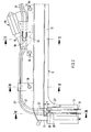
- Fig. 2
- die abgebrochene Draufsicht auf den Rahmen der Schiebedachkonstruktion,
- Fig. 3
- den abgebrochenen Schnitt entlang der Linie III-III in Fig. 2,
- Fig. 4
- den abgebrochenen Schnitt entlang der Linie IV-IV in Fig. 2 und
- Fig. 5
- den abgebrochenen Schnitt entlang der Linie V-V in Fig. 2.
- 1
- Deckel
- 2
- feste Dachfläche
- 3
- Dachöffnung
- 4
- Glasplatte
- 5
- Deckelrahmen
- 6
- Randspaltdichtung
- 7
- Abkantung
- 8
- Verstärkungsrahmen
- 9
- Rahmen
- 10
- Schraubverbindungen
- 11
- Seitenteile
- 12
- Vorderteil
- 13
- Eckbereiche
- 14
- Querteil
- 15
- Führungskanäle
- 16
- Antriebskabel
- 17
- Führungsschuhe
- 18
- Antriebsritzel
- 19
- Antriebsvorrichtung
- 20
- Drahtwicklungen
- 21
- Führungsrohre
- 22
- Verbindungselemente
- 23
- Enden der Führungsrohre
- 24
- Hohlraum
- 25
- Eintrittsenden
- 26
- Vorsprung
- 27
- Anschlagelement
- 28
- Schrauben
- a
- Abstand
Claims (10)
- Rahmen für ein Fahrzeug-Schiebedach oder -Schiebehebedach, der unterhalb einer festen Dachfläche (2) montierbar, zur Führung und Halterung eines verschiebbaren oder verschiebbaren und schwenkbaren, einer entsprechenden Dachöffnung (3) in der festen Dachfläche (2) zugeordneten Deckels (1) ausgebildet ist, zwei parallel zueinander angeordnete Seitenteile (11) aus Metall und ein als Kunststoffspritzteil ausgebildetes Vorderteil (12) aufweist, welches als Übergang zu den Seitenteilen (11) angeformte Eckbereiche (13) besitzt, wobei die Seitenteile (11) in Führungskanälen (15) Antriebskabel (16) drucksteif führen, die mit dem über Führungsschuhe (17) an den Seitenteilen (11) geführten Deckel (1) in Antriebsverbindung stehen, in am Vorderteil (12) angebrachten Führungsrohren (21) verlaufen und mit einer am Vorderteil (12) angeordneten Antriebsvorrichtung (19) zum Verschieben der Antriebskabel (16) in den Führungsrohren (21) und den Führungskanälen (15) eingreifen, dadurch gekennzeichnet, daß die Führungsrohre (21) in den Eckbereichen (13) des Vorderteils (12) vor den jeweils zugehörigen Führungskanälen (15) der Seitenteile (11) jeweils mit Abstand (a) enden, und daß diese Abstände durch sowohl an die Eckbereiche als auch an die Seitenteile fest angeschlossene Verbindungselemente aus Kunststoff überbrückt sind.
- Rahmen nach Anspruch 1, dadurch gekennzeichnet, daß die Verbindungselemente aus Kunststoff einteilig mit den Eckbereichen geformt sind.
- Rahmen nach Anspruch 1 oder 2, dadurch gekennzeichnet, daß die Enden (23) der Führungsrohre (21) in das Kunststoffmaterial der Eckbereiche (13) durch Umspritzen eingebettet sind, wobei in den Verbindungselementen (22) an die Enden (23) der Führungsrohre (21) jeweils ein fluchtend mit dem Führungsrohr (21) anschließender Hohlraum (24) gebildet ist, der an der Stoßfläche des Verbindungselements (22) mit dem Seitenteil (11) und fluchtend mit dem zugehörigen Kabelführungskanal (15) endet.
- Rahmen nach einem der Ansprüche 1 bis 3, dadurch gekennzeichnet, daß die Enden (23) der Führungsrohre (21) trichterförmig erweitert sind.
- Rahmen nach Anspruch 3 oder 4, dadurch gekennzeichnet, daß die Querschnittsabmessungen der Hohlräume (24) größer als die Innendurchmesser der Führungsrohre (21) und der Kabelführungskanäle (15) sind.
- Rahmen nach einem der Ansprüche 3 bis 5, dadurch gekennzeichnet, daß die Hohlräume (24) zylindrisch geformt sind.
- Rahmen nach einem der Ansprüche 3 bis 6, dadurch gekennzeichnet, daß die Eintrittsenden (25) der Kabelführungskanäle (15) ebenfalls trichterförmig erweitert sind.
- Rahmen nach einem der Ansprüche 1 bis 7, dadurch gekennzeichnet, daß an den Eckbereichen jeweils ein Vorsprung (26) zur positionierten Auflagerung des zugehörigen Seitenteils (11) und ein seitliches Anschlagelement (27) zur positionierten Anlage des Seitenteils angeformt sind.
- Rahmen nach Anspruch 8, dadurch gekennzeichnet, daß das Vorderteil (12) und die Seitenteile (11) mittels der Vorsprünge (26) fest miteinander verbindbar sind.
- Rahmen nach den Ansprüchen 8 und 9, dadurch gekennzeichnet, daß die feste Verbindung zwischen Vorderteil (12) und Seitenteilen (11) durch Schrauben (28) od. dgl. erfolgt, die durch die Vorsprünge (26) und die Seitenteile (11) hindurchgeführt sind.
Applications Claiming Priority (2)
| Application Number | Priority Date | Filing Date | Title |
|---|---|---|---|
| DE10144742 | 2001-09-11 | ||
| DE10144742A DE10144742C2 (de) | 2001-09-11 | 2001-09-11 | Rahmen für ein Fahrzeug-Schiebedach oder -Schiebehebedach |
Publications (2)
| Publication Number | Publication Date |
|---|---|
| EP1291216A1 true EP1291216A1 (de) | 2003-03-12 |
| EP1291216B1 EP1291216B1 (de) | 2006-08-30 |
Family
ID=7698641
Family Applications (1)
| Application Number | Title | Priority Date | Filing Date |
|---|---|---|---|
| EP02014684A Expired - Lifetime EP1291216B1 (de) | 2001-09-11 | 2002-07-03 | Rahmen für ein Fahrzeug-Schiebedach oder -Schiebehebedach |
Country Status (3)
| Country | Link |
|---|---|
| US (1) | US6601911B2 (de) |
| EP (1) | EP1291216B1 (de) |
| DE (2) | DE10144742C2 (de) |
Cited By (3)
| Publication number | Priority date | Publication date | Assignee | Title |
|---|---|---|---|---|
| EP1721770A3 (de) * | 2005-05-11 | 2006-12-13 | ArvinMeritor GmbH | Führungsschiene für ein Kfz-Schiebedachsystem |
| EP1806251A1 (de) * | 2006-01-05 | 2007-07-11 | Magna Car Top Systems GmbH | Dach für ein Kraftfahrzeug |
| WO2017085193A1 (de) * | 2015-11-20 | 2017-05-26 | Webasto SE | Rahmen für ein fahrzeugdach |
Families Citing this family (14)
| Publication number | Priority date | Publication date | Assignee | Title |
|---|---|---|---|---|
| DE10247556A1 (de) * | 2002-10-11 | 2004-04-22 | Bayerische Motoren Werke Ag | Fahrzeug mit einem längs verlagerbaren Fahrzeugverdeck |
| EP1634747B1 (de) * | 2003-05-20 | 2008-04-02 | Grupo Antolin-Ingenieria, S.A. | Schiebedachstützrahmen für ein kraftfahrzeug |
| DE10351734B3 (de) * | 2003-11-06 | 2005-04-28 | Webasto Ag Fahrzeugtechnik | Führungsschiene und Dachrahmen für ein Dachöffnungssystem eines Fahrzeugs |
| DE102005047390B4 (de) * | 2005-10-04 | 2008-01-17 | Webasto Ag | Trägerrahmen, insbesondere für Dachsysteme im Kraftfahrzeugbereich |
| US7437875B2 (en) * | 2005-10-14 | 2008-10-21 | Patrick Zuili | Thermally driven cooling systems |
| DE102005057741A1 (de) * | 2005-12-02 | 2007-06-06 | Webasto Ag | Antriebsvorrichtun für ein bewegliches Fahrzeugteil |
| DE102006002003A1 (de) | 2006-01-16 | 2007-07-26 | Webasto Ag | Anbindungsvorrichtung für zumindest ein Führungsrohr an zumindest eine Führungsschiene, insbesondere eines Schiebedaches |
| DE102006002004B4 (de) | 2006-01-16 | 2008-01-10 | Webasto Ag | Anbindungsvorrichtung für zumindest ein Führungsrohr an zumindest eine Führungsschiene, insbesondere eines Schiebedaches |
| DE202014100220U1 (de) | 2014-01-20 | 2014-02-25 | Roof Systems Germany Gmbh | Kabelführungssystem für ein Fahrzeugschiebedach sowie Fahrzeugschiebedach |
| DE102015119405A1 (de) * | 2015-11-11 | 2017-05-11 | Roof Systems Germany Gmbh | Schiebedachmodul und Verfahren zur Herstellung des Schiebedachmoduls |
| JP2017128264A (ja) * | 2016-01-21 | 2017-07-27 | アイシン精機株式会社 | ルーフ装置 |
| DE102017211664B4 (de) * | 2017-07-07 | 2023-04-13 | Bos Gmbh & Co. Kg | Dachsystem für ein Kraftfahrzeug |
| DE102018110124A1 (de) | 2018-04-26 | 2019-10-31 | Webasto SE | Verfahren zum Herstellen einer Antriebskabelhalterung für ein Fahrzeugdach und Bauteil für ein Fahrzeugdach |
| DE102020133729A1 (de) | 2020-12-16 | 2022-06-23 | Webasto SE | Verfahren zum Herstellen einer Antriebskabelhalterung für ein Fahrzeugdach und Bauteil für ein Fahrzeugdach |
Citations (7)
| Publication number | Priority date | Publication date | Assignee | Title |
|---|---|---|---|---|
| DE3532103A1 (de) * | 1985-09-09 | 1987-03-19 | Webasto Werk Baier Kg W | Rahmenanordnung fuer ein fahrzeugdach |
| US5104178A (en) * | 1990-05-07 | 1992-04-14 | Webasto Ag Fahrzeugtechnik | Frame for a vehicle sliding roof or a sliding lifting roof and method for forming same |
| JPH10203173A (ja) * | 1997-01-20 | 1998-08-04 | Nissan Motor Co Ltd | サンルーフレール構造 |
| JPH10297283A (ja) * | 1997-04-30 | 1998-11-10 | Daikyo Webasto Co Ltd | サンルーフ装置のフレーム構造 |
| JPH11278059A (ja) * | 1998-03-27 | 1999-10-12 | Oi Seisakusho Co Ltd | サンルーフのリッド昇降装置 |
| JP2001063371A (ja) * | 1999-08-30 | 2001-03-13 | Yachiyo Industry Co Ltd | サンルーフのフレーム構造 |
| DE10053531A1 (de) * | 1999-10-29 | 2001-05-23 | Aisin Seiki | Schiebedach |
Family Cites Families (2)
| Publication number | Priority date | Publication date | Assignee | Title |
|---|---|---|---|---|
| AT300590B (de) * | 1969-07-14 | 1972-07-25 | Webasto Werk Baier Kg W | Vorrichtung zum Öffnen und Schließen eines Schiebedaches für Fahrzeuge |
| JPH07149153A (ja) * | 1993-11-29 | 1995-06-13 | Aisin Seiki Co Ltd | 車両用サンルーフ装置 |
-
2001
- 2001-09-11 DE DE10144742A patent/DE10144742C2/de not_active Expired - Fee Related
-
2002
- 2002-07-03 EP EP02014684A patent/EP1291216B1/de not_active Expired - Lifetime
- 2002-07-03 DE DE50207982T patent/DE50207982D1/de not_active Expired - Fee Related
- 2002-09-10 US US10/238,416 patent/US6601911B2/en not_active Expired - Fee Related
Patent Citations (7)
| Publication number | Priority date | Publication date | Assignee | Title |
|---|---|---|---|---|
| DE3532103A1 (de) * | 1985-09-09 | 1987-03-19 | Webasto Werk Baier Kg W | Rahmenanordnung fuer ein fahrzeugdach |
| US5104178A (en) * | 1990-05-07 | 1992-04-14 | Webasto Ag Fahrzeugtechnik | Frame for a vehicle sliding roof or a sliding lifting roof and method for forming same |
| JPH10203173A (ja) * | 1997-01-20 | 1998-08-04 | Nissan Motor Co Ltd | サンルーフレール構造 |
| JPH10297283A (ja) * | 1997-04-30 | 1998-11-10 | Daikyo Webasto Co Ltd | サンルーフ装置のフレーム構造 |
| JPH11278059A (ja) * | 1998-03-27 | 1999-10-12 | Oi Seisakusho Co Ltd | サンルーフのリッド昇降装置 |
| JP2001063371A (ja) * | 1999-08-30 | 2001-03-13 | Yachiyo Industry Co Ltd | サンルーフのフレーム構造 |
| DE10053531A1 (de) * | 1999-10-29 | 2001-05-23 | Aisin Seiki | Schiebedach |
Non-Patent Citations (4)
| Title |
|---|
| PATENT ABSTRACTS OF JAPAN vol. 1998, no. 13 30 November 1998 (1998-11-30) * |
| PATENT ABSTRACTS OF JAPAN vol. 1999, no. 02 26 February 1999 (1999-02-26) * |
| PATENT ABSTRACTS OF JAPAN vol. 2000, no. 01 31 January 2000 (2000-01-31) * |
| PATENT ABSTRACTS OF JAPAN vol. 2000, no. 20 10 July 2001 (2001-07-10) * |
Cited By (4)
| Publication number | Priority date | Publication date | Assignee | Title |
|---|---|---|---|---|
| EP1721770A3 (de) * | 2005-05-11 | 2006-12-13 | ArvinMeritor GmbH | Führungsschiene für ein Kfz-Schiebedachsystem |
| US7802400B2 (en) | 2005-05-11 | 2010-09-28 | Arvinmeritor Gmbh | Guide rail for a sliding roof system in a motor vehicle |
| EP1806251A1 (de) * | 2006-01-05 | 2007-07-11 | Magna Car Top Systems GmbH | Dach für ein Kraftfahrzeug |
| WO2017085193A1 (de) * | 2015-11-20 | 2017-05-26 | Webasto SE | Rahmen für ein fahrzeugdach |
Also Published As
| Publication number | Publication date |
|---|---|
| DE10144742A1 (de) | 2003-03-27 |
| US6601911B2 (en) | 2003-08-05 |
| DE10144742C2 (de) | 2003-06-26 |
| US20030047968A1 (en) | 2003-03-13 |
| DE50207982D1 (de) | 2006-10-12 |
| EP1291216B1 (de) | 2006-08-30 |
Similar Documents
| Publication | Publication Date | Title |
|---|---|---|
| EP0455975B1 (de) | Rahmen für ein Fahrzeug-Schiebedach oder -Schiebehebedach | |
| DE10144742C2 (de) | Rahmen für ein Fahrzeug-Schiebedach oder -Schiebehebedach | |
| EP0937853B1 (de) | Betätigungseinrichtung für eine Schiebetür, insbesondere für Kraftfahrzeuge | |
| DE10144738B4 (de) | Rahmen für ein Fahrzeug-Schiebedach oder -Schiebehebedach | |
| EP1960220B1 (de) | Rollokupplung für ein fahrzeugsonnendachrollo, sowie rolloband, sowie fahrzeugsonnendachrollo | |
| DE4422646C1 (de) | Rahmen für Fahrzeugdächer | |
| DE102016009136B4 (de) | Kraftwagen mit einem Dachmodul | |
| EP0888918A2 (de) | Betätigungsanordnung für den Deckel eines Kraftfahrzeugschiebedachs | |
| DE102008064548A1 (de) | Rahmenvorrichtung eines Fahrzeugdaches mit einer Antriebseinheit | |
| DE10203904B4 (de) | Antriebsvorrichtung für Kraftfahrzeugschiebedächer | |
| DE202006003901U1 (de) | Schiebetüranordnung für ein Kraftfahrzeug | |
| DE202005018138U1 (de) | Kabelführung für ein Antriebskabel eines bewegbaren Fahrzeugteils | |
| DE4419175C1 (de) | Antriebsvorrichtung für Sonnendächer von Kraftfahrzeugen | |
| DE4301635C1 (de) | Rahmenanordnung für ein Fahrzeugdach | |
| DE19732700B4 (de) | Rahmenanordnung für ein Deckelteil eines Fahrzeugdaches | |
| DE10135406B4 (de) | Fahrzeugdach mit einer Dachöffnung | |
| WO1995001492A1 (de) | Seilzug-fensterheber | |
| DE2912666A1 (de) | Verbindungseinrichtung fuer ein antriebskabel | |
| DE102017102002A1 (de) | Lager- und Antriebsvorrichtung eines verstellbaren Deckels eines Fahrzeugdaches | |
| DE102009036780B4 (de) | Führungseinrichtung für eine seilzugbetätigte Verstellvorrichtung | |
| EP1849635B1 (de) | Fensterrollo, welches an der Innenseite eines Kraftfahrzeugfensters anzuordnen ist | |
| DE10011747C2 (de) | Kulissenelement zur festen Anbringung an einem Deckelelement | |
| DE102005032564A1 (de) | Rahmenanordnung für die verschiebbare Lagerung eines öffnungsfähigen Fahrzeug-Dachteils | |
| DE10123424B4 (de) | Antrieb für ein verstellbares Schließelement eines Fahrzeugdaches | |
| DE102005040837B4 (de) | Antriebsvorrichtung für zumindest ein bewegbares Fahrzeugteil |
Legal Events
| Date | Code | Title | Description |
|---|---|---|---|
| PUAI | Public reference made under article 153(3) epc to a published international application that has entered the european phase |
Free format text: ORIGINAL CODE: 0009012 |
|
| AK | Designated contracting states |
Kind code of ref document: A1 Designated state(s): AT BE BG CH CY CZ DE DK EE ES FI FR GB GR IE IT LI LU MC NL PT SE SK TR Designated state(s): AT BE BG CH CY CZ DE DK EE ES FI FR GB GR IE IT LI LU MC NL PT SE SK TR |
|
| AX | Request for extension of the european patent |
Extension state: AL LT LV MK RO SI |
|
| 17P | Request for examination filed |
Effective date: 20030415 |
|
| AKX | Designation fees paid |
Designated state(s): DE FR IT NL |
|
| GRAP | Despatch of communication of intention to grant a patent |
Free format text: ORIGINAL CODE: EPIDOSNIGR1 |
|
| GRAS | Grant fee paid |
Free format text: ORIGINAL CODE: EPIDOSNIGR3 |
|
| GRAA | (expected) grant |
Free format text: ORIGINAL CODE: 0009210 |
|
| AK | Designated contracting states |
Kind code of ref document: B1 Designated state(s): DE FR IT NL |
|
| PG25 | Lapsed in a contracting state [announced via postgrant information from national office to epo] |
Ref country code: IT Free format text: LAPSE BECAUSE OF FAILURE TO SUBMIT A TRANSLATION OF THE DESCRIPTION OR TO PAY THE FEE WITHIN THE PRESCRIBED TIME-LIMIT;WARNING: LAPSES OF ITALIAN PATENTS WITH EFFECTIVE DATE BEFORE 2007 MAY HAVE OCCURRED AT ANY TIME BEFORE 2007. THE CORRECT EFFECTIVE DATE MAY BE DIFFERENT FROM THE ONE RECORDED. Effective date: 20060830 |
|
| REF | Corresponds to: |
Ref document number: 50207982 Country of ref document: DE Date of ref document: 20061012 Kind code of ref document: P |
|
| ET | Fr: translation filed | ||
| PLBE | No opposition filed within time limit |
Free format text: ORIGINAL CODE: 0009261 |
|
| STAA | Information on the status of an ep patent application or granted ep patent |
Free format text: STATUS: NO OPPOSITION FILED WITHIN TIME LIMIT |
|
| 26N | No opposition filed |
Effective date: 20070531 |
|
| NLV4 | Nl: lapsed or anulled due to non-payment of the annual fee |
Effective date: 20080201 |
|
| PG25 | Lapsed in a contracting state [announced via postgrant information from national office to epo] |
Ref country code: NL Free format text: LAPSE BECAUSE OF NON-PAYMENT OF DUE FEES Effective date: 20080201 Ref country code: DE Free format text: LAPSE BECAUSE OF NON-PAYMENT OF DUE FEES Effective date: 20080201 |
|
| REG | Reference to a national code |
Ref country code: FR Ref legal event code: ST Effective date: 20080331 |
|
| PG25 | Lapsed in a contracting state [announced via postgrant information from national office to epo] |
Ref country code: FR Free format text: LAPSE BECAUSE OF NON-PAYMENT OF DUE FEES Effective date: 20070731 |