EP1291216A1 - Frame for a vehicle sliding roof or tilt-sliding roof - Google Patents
Frame for a vehicle sliding roof or tilt-sliding roof Download PDFInfo
- Publication number
- EP1291216A1 EP1291216A1 EP02014684A EP02014684A EP1291216A1 EP 1291216 A1 EP1291216 A1 EP 1291216A1 EP 02014684 A EP02014684 A EP 02014684A EP 02014684 A EP02014684 A EP 02014684A EP 1291216 A1 EP1291216 A1 EP 1291216A1
- Authority
- EP
- European Patent Office
- Prior art keywords
- side parts
- guide
- frame according
- guide tubes
- front part
- Prior art date
- Legal status (The legal status is an assumption and is not a legal conclusion. Google has not performed a legal analysis and makes no representation as to the accuracy of the status listed.)
- Granted
Links
Images


Classifications
-
- B—PERFORMING OPERATIONS; TRANSPORTING
- B60—VEHICLES IN GENERAL
- B60J—WINDOWS, WINDSCREENS, NON-FIXED ROOFS, DOORS, OR SIMILAR DEVICES FOR VEHICLES; REMOVABLE EXTERNAL PROTECTIVE COVERINGS SPECIALLY ADAPTED FOR VEHICLES
- B60J7/00—Non-fixed roofs; Roofs with movable panels, e.g. rotary sunroofs
- B60J7/02—Non-fixed roofs; Roofs with movable panels, e.g. rotary sunroofs of sliding type, e.g. comprising guide shoes
- B60J7/022—Sliding roof trays or assemblies
Definitions
- the invention relates to a frame for a vehicle sunroof or sliding sunroof, according to the generic term of claim 1.
- Such a known frame (DE 40 14 487 C1) is to the Joints between the corner areas of the front part and the side parts formed so that the ends of the guide tubes protrude beyond the corner areas of the front part and can be inserted into the cable duct in the side panels are.
- This is intended to connect the front part during assembly and side parts the required torsional rigidity and dimensional accuracy can be achieved so that these protruding guide tube ends as assembly aids for assembling and aligning the longitudinal parts and the front part serve the frame. It is also said to be a smoother Transition between the protruding ends of the guide tubes and the guide channels in the side panels his.
- the invention has for its object a framework provide training specified in the beginning, in which at the transition points between the guide tubes of the front part and the guide channels of the side parts no noise arise and no engine vibrations are transmitted can.
- the plastic fasteners can be used as separate Parts should be formed on the one hand with the corner areas of the front part and on the other hand with the side parts, for example by means of clip connections in a positioned position are firmly connectable, preferably the connecting elements however an integral part of the corner areas themselves, as stated in claim 2.
- the ends of the guide tubes are a continuation of the inventive concept according to claim 3 within the corner areas overmoulded with plastic, one on each guide tube the distance to the associated guide channel in the side part bridging cavity in alignment in the connecting element connected.
- the ends the guide tubes and, according to claim 7, the inlet ends the cable routing channels are funnel-shaped.
- the one specified in claim 5 also aims in the same direction Measure according to which the cross-sectional dimensions of the cavities larger than the inside diameter of the guide tubes and the Cable routing channels are.
- the drive cables come with the inner walls of the cavities, accordingly Claim 6 are expediently cylindrical, with displacement movements not in touch.
- projections for the side parts on the corner areas and side stop elements for the side parts molded in one piece from plastic, as in claim 8 are advantageous projections for the side parts on the corner areas and side stop elements for the side parts molded in one piece from plastic, as in claim 8 is specified.
- These projections can according to claim 9 to achieve an easy to manufacture union of Frame parts can be used. This can be done according to claim 10 screw connections through the projections and the side parts be used.
- the lid 1 closes the one arranged in the fixed roof surface 2 Roof opening 3 and can in the typical for sunroofs Movement sequence after lowering its rear edge under the rear fixed roof surface 2 can be moved in whole or in part. If the sunroof is sliding, it can Cover 1 in the additional movement sequence typical for this roof type also like hinged flaps starting from the closed position by lifting its rear edge if necessary, stepless to form a rear ventilation opening be pivoted upwards.
- it is a cover 1 with a glass plate 4, one of Plastic foamed lid frame 5 and one Cover plate 4 and the cover frame 5 surrounding edge gap seal 6, which is used for tight contact with the roof opening 3 delimiting fold 7 of the fixed roof surface 2 forming Roof sheet is determined.
- On the fixed roof surface 2 or their Bend 7 is a roof opening 3 from below or completely partially surrounding reinforcement frame 8 attached.
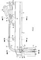
- the frame 9 described in more detail below is below fixed roof surface 2 on several spaced apart Locations, three of which can be seen in FIG. 2, by means of Screw connections 10 mounted, one of which is shown in Fig. 4
- the frame 9 comprises two arranged parallel to each other Side parts 11 made of metal, for example an aluminum extruded profile are formed, and an as Plastic injection molded front part 12, which as Transition to the side parts 11 has molded corner areas 13.
- the two side parts are approximately in the middle of their length 11 against each other by a cross member 14 attached to it stiffened, as indicated in Fig. 1. 2 is only the left side part 11 shown because the right side part and the corner area 13 is designed as a mirror image are.
- the drive cables 16 of which in FIGS and 3 only short sections are shown with the lid 1, the guide shoes 17 (Fig. 1) to the Side parts 11 is guided in drive connection.
- a drive pinion 18 is rotatably mounted, which in shown example of an electric motor gear unit as Drive device 19 optionally in one or the other Direction of rotation is drivable.
- the drive device can also be designed as a hand crank drive.
- the drive pinion 18 is constantly with both drive cables 16 in meshing, so that rotations of the drive pinion 18th opposite movement of the two drive cables 16 in their guides.
- the drive cables 16 are for meshing with helical wire windings 20, as can be clearly seen from FIG. 3, so that they are from the corresponding toothed drive pinion 18th be driven like a rack.
- the front part 12 there are 16 guide tubes for guiding the drive cables 21 on the side of the Front part 12 attached, for example by in places Injection molding of the guide tubes 21 with the plastic material of the front part 12, so that after the molding process the previously in the injection mold inserted guide tubes 21 an integral part of the front part 12.
- These connection points of the guide tubes 21 with the front part 12 are shown in FIGS. 2, 4 and 5 out.
- the guide tubes 21 end in the corner regions 13 of the front part 12 in front of the associated guide channels 15 of the side parts 11 with a distance a.
- These distances a between those that belong together but are decoupled from each other Guide tube / guide channel pairs 21/15 through to both the corner areas 13 and the side parts 11 permanently connected connecting elements 22 made of plastic bridged.
- the ends 23 of the guide tubes 21 are in the plastic material the corner areas 13 embedded by overmolding.
- In the connecting elements 22 is at the ends 23 of the guide tubes 21 each in alignment with the guide tube 21 subsequent cavity 24 formed.
- This cylindrical shape Cavity ends in each case on the abutting surface of the connecting element 22 with the associated side part 11 and aligned with the associated cable duct 15.
- the ends 23 the guide tubes 21 are approximately funnel-shaped. Accordingly are also the inlet ends 25 of the cable routing channels 15 also expanded in a funnel shape. In connection so that the cross-sectional dimensions of the cavities 24, i.e.
- 13 is at the corner regions a projection 26 for the positioned support of the associated Molded on part 11.
- a side stop element 27 for the positioned contact of the side part 11 molded onto each corner area 13. Projection 26 and stop element 27 ensure that when assembling the frame parts 11 and 12, the guide channels 15 with the guide tubes 21 precisely to get axially aligned.
- a frame 9 for a vehicle sunroof is proposed or sliding sunroof, consisting essentially of one Plastic injection molded front part 12 with molded corner areas 13 and two firmly connected via the corner areas Side parts 11 made of metal, with the front part 12 Guide tubes 21 integrated and in the side parts 11 on it subsequent guide channels 15 are arranged, which are common Drive cable 16 for relocating a cover 1 relative to a roof opening 3 of the roof structure pressure-resistant.
- the associated guide tubes 21 and the guide channels 15 do not touch each other, but are separated by distances a that are bridged by connecting elements 22, from each other decoupled so that originating from the cable drive system Vibrations from the guide tubes 21 not on the metallic Side parts 11 can be transferred.
- the ends 23 the guide tubes 21 and the inlet ends spaced therefrom 25 of the guide channels 15 and the ends 23, 25 bridging cavity 24 are stepless in a special way trained to be noises during drive cable shifts avoid.
- the proposed frame can also be used for top ridge sliding roofs (Spoiler roofs) can be used.
Landscapes
- Engineering & Computer Science (AREA)
- Mechanical Engineering (AREA)
- Seal Device For Vehicle (AREA)
Abstract
Description
Die Erfindung bezieht sich auf einen Rahmen für ein Fahrzeug-Schiebedach
oder -Schiebehebedach, entsprechend dem Oberbegriff
des Patentanspruchs 1.The invention relates to a frame for a vehicle sunroof
or sliding sunroof, according to the generic term
of
Ein derartiger bekannter Rahmen (DE 40 14 487 C1) ist an den Verbindungsstellen zwischen den Eckbereichen des Vorderteils und den Seitenteilen so ausgebildet, daß die Enden der Führungsrohre über die Eckbereiche des Vorderteils überstehen und in die Kabelführungskanäle in den Seitenteilen einsteckbar sind. Hierdurch soll bei der Montage die Verbindung von Vorderteil und Seitenteilen die für erforderlich gehaltene Verwindungssteifigkeit und Maßhaltigkeit erzielt werden, so daß diese überstehenden Führungsrohrenden als Montagehilfsmittel zum Zusammensetzen und Ausrichten der Längsteile und des Vorderteils des Rahmens dienen. Weiterhin soll dadurch ein glatter Übergang zwischen den überstehenden Enden der Führungsrohre und den Führungskanälen in den Seitenteilen vorhanden sein.Such a known frame (DE 40 14 487 C1) is to the Joints between the corner areas of the front part and the side parts formed so that the ends of the guide tubes protrude beyond the corner areas of the front part and can be inserted into the cable duct in the side panels are. This is intended to connect the front part during assembly and side parts the required torsional rigidity and dimensional accuracy can be achieved so that these protruding guide tube ends as assembly aids for assembling and aligning the longitudinal parts and the front part serve the frame. It is also said to be a smoother Transition between the protruding ends of the guide tubes and the guide channels in the side panels his.
Auf diese Weise entsteht an den Übergangsstellen zwischen den Rohrenden und den Führungskanälen aber eine Stufenbildung, die bei Verschiebungen der Antriebskabel zu unerwünschter Geräuschbildung führen kann, wenn die Drahtgewindewicklungen der Antriebskabel über die Stufen laufen. Darüber hinaus können insbesondere bei einer mit Elektromotor ausgerüsteten Antriebsvorrichtung Motorschwingungen in unerwünschter Weise direkt über die Führungsrohre auf die aus Metall bestehenden Seitenteile übertragen werden.This creates at the transition points between the Pipe ends and the guide channels but a step that when the drive cables are shifted to undesirable noise can lead if the wire thread windings of the Run the drive cable over the steps. In addition, you can especially in the case of a drive device equipped with an electric motor Engine vibrations in an undesirable manner directly over the guide tubes to the metal ones Side parts are transferred.
Der Erfindung liegt die Aufgabe zugrunde, einen Rahmen der eingangs angegebenen Ausbildung bereitzustellen, bei welchem an den Übergangsstellen zwischen den Führungsrohren des Vorderteils und den Führungskanälen der Seitenteile keine Geräusche entstehen und keine Motorschwingungen übertragen werden können.The invention has for its object a framework provide training specified in the beginning, in which at the transition points between the guide tubes of the front part and the guide channels of the side parts no noise arise and no engine vibrations are transmitted can.
Diese Aufgabe wird erfindungsgemäß durch die im Patentanspruch
1 angegebenen Merkmale gelöst. Vorteilhafte oder zweckmäßige
Weiterbildungen sind in den Unteransprüchen angegeben und
nachfolgend ebenfalls beschrieben.This object is achieved by the
Durch den Abstand zwischen den Führungsrohrenden und den Führungskanälen bzw. den die Führungskanäle aufweisenden metallischen Seitenteilen sind die Führungsrohre von den Seitenteilen gewissermaßen entkoppelt, so daß unmittelbare Schwingungsübertragungen zwischen diesen Elementen ausgeschlossen sind. Durch die Abstände zwischen den Führungsrohrenden und den Führungskanälen in den Seitenteilen treten zwischen diesen unterschiedlichen Abschnitten der Antriebskabelführung auch keine Stufenbildungen auf.Due to the distance between the guide tube ends and the guide channels or the metallic having the guide channels Side parts are the guide tubes from the side parts to a certain extent decoupled, so that direct vibration transmissions between these elements are excluded. By the distances between the guide tube ends and the guide channels in the side parts occur between these different Sections of the drive cable routing also none Step formation on.
Die Verbindungselemente aus Kunststoff können als getrennte
Teile ausgebildet sein, die einerseits mit den Eckbereichen
des Vorderteils und andererseits mit den Seitenteilen beispielsweise
durch Klipsverbindungen in positionierter Lage
fest verbindbar sind, vorzugsweise sind die Verbindungselemente
jedoch integraler Bestandteil der Eckbereiche selbst,
wie im Anspruch 2 angegeben ist.The plastic fasteners can be used as separate
Parts should be formed on the one hand with the corner areas
of the front part and on the other hand with the side parts, for example
by means of clip connections in a positioned position
are firmly connectable, preferably the connecting elements
however an integral part of the corner areas themselves,
as stated in
Die Enden der Führungsrohre sind in Weiterführung des Erfindungsgedankens
entsprechend Anspruch 3 innerhalb der Eckbereiche
mit Kunststoff umspritzt, wobei an jedes Führungsrohr ein
den Abstand zum jeweils zugehörigen Führungskanal im Seitenteil
überbrückender Hohlraum im Verbindungselement fluchtend
angeschlossen ist.The ends of the guide tubes are a continuation of the inventive concept
according to
Zur Vermeidung jeder Stufenbildung innerhalb der Antriebskabelführung
sind entsprechend Anspruch 4 zweckmäßig die Enden
der Führungsrohre und gemäß Anspruch 7 auch die Eintrittsenden
der Kabelführungskanäle trichterförmig erweitert.To avoid any step formation within the drive cable routing
are appropriate according to
In dieselbe Richtung zielt auch die im Anspruch 5 angegebene
Maßnahme, wonach die Querschnittsabmessungen der Hohlräume
größer als die Innendurchmesser der Führungsrohre und der
Kabelführungskanäle sind. Auf diese Weise kommen die Antriebskabel
mit den Innenwandungen der Hohlräume, die entsprechend
Anspruch 6 zweckmäßig zylindrisch geformt sind, bei Verschiebebewegungen
nicht in Berührung.The one specified in claim 5 also aims in the same direction
Measure according to which the cross-sectional dimensions of the cavities
larger than the inside diameter of the guide tubes and the
Cable routing channels are. In this way, the drive cables come
with the inner walls of the cavities, accordingly
Um eine einfach zu erzielende Ausfluchtung der Führungsrohrenden
mit den Kabelführungskanälen bei der Vereinigung des
Vorderteils mit den Seitenteilen sicherzustellen, sind vorteilhaft
an den Eckbereichen Auflagervorsprünge für die Seitenteile
und seitliche Anschlagelemente für die Seitenteile
einteilig aus Kunststoff angeformt, wie das im Anspruch 8
angegeben ist. Diese Vorsprünge können entsprechend Anspruch 9
zur Erzielung einer einfach herzustellenden Vereinigung der
Rahmenteile herangezogen werden. Hierzu können nach Anspruch
10 durch die Vorsprünge und die Seitenteile geführte Schraubverbindungen
verwendet werden.To make it easy to align the guide tube ends
with the cable routing ducts when uniting the
Ensuring the front part with the side parts are advantageous
projections for the side parts on the corner areas
and side stop elements for the side parts
molded in one piece from plastic, as in
Weitere Einzelheiten der Erfindung werden nachfolgend unter Bezugnahme auf die ein bevorzugtes Ausführungsbeispiel teilweise schematisch darstellenden Zeichnungen näher erläutert. Darin zeigt:
- Fig. 1
- eine Perspektivansicht eines Kraftfahrzeugdachs mit eingebautem Schiebedach, dargestellt mit geschlossenem Deckel,
- Fig. 2
- die abgebrochene Draufsicht auf den Rahmen der Schiebedachkonstruktion,
- Fig. 3
- den abgebrochenen Schnitt entlang der Linie III-III in Fig. 2,
- Fig. 4
- den abgebrochenen Schnitt entlang der Linie IV-IV in Fig. 2 und
- Fig. 5
- den abgebrochenen Schnitt entlang der Linie V-V in Fig. 2.
- Fig. 1
- 1 shows a perspective view of a motor vehicle roof with a built-in sliding roof, shown with the lid closed,
- Fig. 2
- the broken top view of the frame of the sunroof construction,
- Fig. 3
- the broken section along the line III-III in Fig. 2,
- Fig. 4
- the broken section along the line IV-IV in Fig. 2 and
- Fig. 5
- the broken section along the line VV in Fig. 2nd
Der Deckel 1 schließt die in der festen Dachfläche 2 angeordnete
Dachöffnung 3 und kann in dem für Schiebedächer typischen
Bewegungsablauf nach Absenken seiner Hinterkante unter die
hintere feste Dachfläche 2 ganz oder teilweise verschoben werden.
Wenn es sich um ein Schiebehebedach handelt, kann der
Deckel 1 in dem für diesen Dachtyp typischen zusätzlichen Bewegungsablauf
außerdem noch nach Art vorn scharnierter Klappen
ausgehend von der Schließstellung durch Anheben seiner Hinterkante
ggf. stufenlos zur Bildung einer hinteren Lüftungsöffnung
nach oben verschwenkt werden. Im Ausführungsbeispiel handelt
es sich um einen Deckel 1 mit Glasplatte 4, einem aus
Kunststoff daran angeschäumten Deckelrahmen 5 und einer die
Deckelplatte 4 und den Deckelrahmen 5 umgebenden Randspaltdichtung
6, die zur dichten Anlage an eine die Dachöffnung 3
begrenzende Abkantung 7 des die feste Dachfläche 2 bildenden
Dachblechs bestimmt ist. An der festen Dachfläche 2 bzw. ihrer
Abkantung 7 ist von unten her ein die Dachöffnung 3 ganz oder
teilweise umgebender Verstärkungsrahmen 8 befestigt.The
Obwohl in Fig. 2 nur der Rahmen 9 in Draufsicht dargestellt
ist, sind in den Schnittdarstellungen gemäß den Figuren 3 bis
5 jeweils auch die oberhalb des Rahmens 9 befindlichen Teile
der Dachkonstruktion in ihrer Lage nach Montage des Rahmens
dargestellt, nämlich der Deckel 1, die feste Dachfläche 2 und
der Verstärkungsrahmen 8.Although only the
Der nachfolgend näher beschriebene Rahmen 9 ist unterhalb der
festen Dachfläche 2 an mehreren voneinander beabstandeten
Stellen, von denen aus Fig. 2 drei ersichtlich sind, mittels
Schraubverbindungen 10 montiert, von denen eine in Fig. 4 dargestellt
ist.Der Rahmen 9 umfaßt zwei parallel zueinander angeordnete
Seitenteile 11 aus Metall, die beispielsweise aus
einem Aluminium-Strangpreßprofil gebildet sind, und ein als
Kunststoffspritzteil ausgebildetes Vorderteil 12, welches als
Übergang zu den Seitenteilen 11 angeformte Eckbereiche 13 besitzt.
Etwa in der Mitte ihrer Länge sind die beiden Seitenteile
11 durch ein daran befestigtes Querteil 14 gegeneinander
ausgesteift, wie in Fig. 1 angedeutet ist. In Fig. 2 ist nur
das linke Seitenteil 11 dargestellt, weil das rechte Seitenteil
und der Eckbereich 13 entsprechend spiegelbildlich ausgeführt
sind.The
In den Seitenteilen 11 befinden sich jeweils zwei Führungskanäle
15, in denen Antriebskabel 16 drucksteif verschiebbar
geführt sind. Die Antriebskabel 16, von denen in den Figuren 2
und 3 jeweils nur kurze Abschnitte eingezeichnet sind, stehen
mit dem Deckel 1, der über Führungsschuhe 17 (Fig. 1) an den
Seitenteilen 11 geführt ist, in Antriebsverbindung. Am Vorderteil
12 ist ein Antriebsritzel 18 drehbar gelagert, welches im
gezeigten Beispiel von einer Elektromotor-Getriebe-Einheit als
Antriebsvorrichtung 19 wahlweise in der einen oder anderen
Drehrichtung antreibbar ist. Die Antriebsvorrichtung kann aber
auch als Handkurbelantrieb ausgebildet sein.There are two guide channels in each of the
Das Antriebsritzel 18 steht mit beiden Antriebskabeln 16 ständig
im Zahneingriff, so daß Drehungen des Antriebsritzels 18
jeweils gegenläufige Verschiebebewegungen der beiden Antriebskabel
16 in ihren Führungen hervorrufen. Die Antriebskabel 16
sind für den Zahneingriff mit schraubenlinienförmigen Drahtwicklungen
20 versehen, wie aus Fig. 3 deutlich erkennbar ist,
so daß sie von dem entsprechend verzahnten Antriebsritzel 18
zahnstangenähnlich angetrieben werden. Dieses Antriebssystem
wird seit Jahrzehnten für Schiebedachantriebe benutzt und bedarf
daher hier keiner näheren Erläuterung.The
Am Vorderteil 12 sind zur Führung der Antriebskabel 16 Führungsrohre
21 auf der der Dachöffnung abgelegenen Seite des
Vorderteils 12 befestigt, beispielsweise durch stellenweises
Umspritzen der Führungsrohre 21 mit dem Kunststoffwerkstoff
des Vorderteils 12, so daß nach dem Formvorgang die vorher in
die Spritzform eingelegten Führungsrohre 21 fester Bestandteil
des Vorderteils 12 sind. Diese Verbindungsstellen der Führungsrohre
21 mit dem Vorderteil 12 gehen aus den Figuren 2, 4
und 5 hervor.On the
Wie aus den Figuren 2 und 3, insbesondere aber aus Fig. 3 zu
ersehen ist, enden die Führungsrohre 21 in den Eckbereichen 13
des Vorderteils 12 vor den jeweils zugehörigen Führungskanälen
15 der Seitenteile 11 mit einem Abstand a. Diese Abstände a
zwischen den jeweils zusammengehörigen, aber voneinander entkoppelten
Führungsrohr-/Führungskanal-Paaren 21/15 werden
durch sowohl an die Eckbereiche 13 als auch an die Seitenteile
11 fest angeschlossene Verbindungselemente 22 aus Kunststoff
überbrückt. Im gezeichneten Beispiel sind diese Verbindungselemente
22 aus Kunststoff einteilig mit den Eckbereichen 13
geformt.As from FIGS. 2 and 3, but in particular from FIG. 3
can be seen, the
Die Enden 23 der Führungsrohre 21 sind hierbei in das Kunststoffmaterial
der Eckbereiche 13 durch Umspritzen eingebettet.
In den Verbindungselementen 22 ist an den Enden 23 der Führungsrohre
21 jeweils ein fluchtend mit dem Führungsrohr 21
anschließender Hohlraum 24 gebildet. Dieser zylindrisch geformte
Hohlraum endet jeweils an der Stoßfläche des Verbindungselements
22 mit dem zugehörigen Seitenteil 11 und fluchtet
mit dem zugehörigen Kabelführungskanal 15. Die Enden 23
der Führungsrohre 21 sind etwa trichterförmig erweitert. Dementsprechend
sind auch die Eintrittsenden 25 der Kabelführungskanäle
15 ebenfalls trichterförmig erweitert. In Verbindung
damit, daß die Querschnittsabmessungen der Hohlräume 24,
d.h. bei zylindrischer Ausbildung ihre Durchmesser, größer
sind als die Innendurchmesser der Führungsrohre 21 und der
Kabelführungskanäle 15, wird sichergestellt, daß an diesen
Überbrückungsstellen zwischen den Führungsrohren 21 und den
Führungskanälen 15 keine Stufenbildung vorhanden ist, die bei
Verschiebebewegungen der Antriebskabel 16 aufgrund der Drahtwicklungen
20 Rattergeräusche hervorrufen könnte. The
Wie Fig. 3 verdeutlicht, ist an den Eckbereichen 13 jeweils
ein Vorsprung 26 zur positionierten Auflagerung des zugehörigen
Seitenteils 11 angeformt. Weiterhin ist ein seitliches Anschlagelement
27 zur positionierten Anlage des Seitenteils 11
an jeden Eckbereich 13 angeformt. Vorsprung 26 und Anschlagelement
27 stellen sicher, daß bei der Montage der Rahmenteile
11 und 12 die Führungskanäle 15 mit den Führungsrohren 21 präzise
zur achsgleichen Fluchtung gelangen.As illustrated in FIG. 3, 13 is at the corner regions
a
Bei der Montage können das Vorderteil 12 und die Seitenteile
11 mittels der Vorsprünge 26 fest miteinander verbunden werden,
wobei diese feste Verbindung durch Schrauben 28 od.dgl.
erfolgt, die sowohl durch die Vorsprünge 26 als auch durch die
Seitenteile 11 hindurchgeführt sind, wie in Fig. 2 angedeutet
ist.When assembling the
Vorgeschlagen wird ein Rahmen 9 für ein Fahrzeug-Schiebedach
oder -Schiebehebedach, bestehend im wesentlichen aus einem aus
Kunststoff spritzgeformten Vorderteil 12 mit angeformten Eckbereichen
13 und zwei über die Eckbereiche fest angeschlossenen
Seitenteilen 11 aus Metall, wobei in das Vorderteil 12
Führungsrohre 21 integriert und in den Seitenteilen 11 daran
anschließende Führungskanäle 15 angeordnet sind, die gemeinsam
Antriebskabel 16 für Verlagerungen eines Deckels 1 relativ zu
einer Dachöffnung 3 der Dachkonstruktion drucksteif führen.
Die zusammengehörenden Führungsrohre 21 und die Führungskanäle
15 berühren sich nicht, sondern sind durch Abstände a, die
durch Verbindungselemente 22 überbrückt werden, voneinander
entkoppelt, so daß aus dem Kabelantriebssystem herrührende
Schwingungen von den Führungsrohren 21 nicht auf die metallischen
Seitenteile 11 übertragen werden können. Die Enden 23
der Führungsrohre 21 und die davon beabstandeten Eintrittsenden
25 der Führungskanäle 15 sowie der die Enden 23, 25
überbrückende Hohlraum 24 sind auf besondere Weise stufenlos
ausgebildet, um Geräusche bei Antriebskabelverschiebungen zu
vermeiden. Der vorgeschlagene Rahmen kann auch bei Oberfirstschiebedächern
(Spoilerdächern) verwendet werden. A
- 11
- Deckelcover
- 22
- feste Dachflächesolid roof area
- 33
- Dachöffnungroof opening
- 44
- Glasplatteglass plate
- 55
- DeckelrahmenLidmaker
- 66
- RandspaltdichtungEdge gap seal
- 77
- Abkantungfold
- 88th
- Verstärkungsrahmenreinforcing frame
- 99
- Rahmenframe
- 1010
- Schraubverbindungenscrew
- 1111
- Seitenteileside panels
- 1212
- Vorderteilfront
- 1313
- Eckbereichecorner areas
- 1414
- Querteilcross section
- 1515
- Führungskanäleguide channels
- 1616
- Antriebskabeldrive cable
- 1717
- Führungsschuheguide shoes
- 1818
- Antriebsritzelpinion
- 1919
- Antriebsvorrichtungdriving device
- 2020
- Drahtwicklungenwire windings
- 2121
- Führungsrohreguide tubes
- 2222
- Verbindungselementefasteners
- 2323
- Enden der FührungsrohreEnds of the guide tubes
- 2424
- Hohlraumcavity
- 2525
- Eintrittsendenentry ends
- 2626
- Vorsprunghead Start
- 2727
- Anschlagelementstop element
- 2828
- Schraubenscrew
- aa
- Abstanddistance
Claims (10)
Applications Claiming Priority (2)
| Application Number | Priority Date | Filing Date | Title |
|---|---|---|---|
| DE10144742A DE10144742C2 (en) | 2001-09-11 | 2001-09-11 | Frame for a vehicle sunroof or sunroof |
| DE10144742 | 2001-09-11 |
Publications (2)
| Publication Number | Publication Date |
|---|---|
| EP1291216A1 true EP1291216A1 (en) | 2003-03-12 |
| EP1291216B1 EP1291216B1 (en) | 2006-08-30 |
Family
ID=7698641
Family Applications (1)
| Application Number | Title | Priority Date | Filing Date |
|---|---|---|---|
| EP02014684A Expired - Lifetime EP1291216B1 (en) | 2001-09-11 | 2002-07-03 | Frame for a vehicle sliding roof or tilt-sliding roof |
Country Status (3)
| Country | Link |
|---|---|
| US (1) | US6601911B2 (en) |
| EP (1) | EP1291216B1 (en) |
| DE (2) | DE10144742C2 (en) |
Cited By (3)
| Publication number | Priority date | Publication date | Assignee | Title |
|---|---|---|---|---|
| EP1721770A3 (en) * | 2005-05-11 | 2006-12-13 | ArvinMeritor GmbH | Guide rail for a motor vehicle sliding roof system |
| EP1806251A1 (en) * | 2006-01-05 | 2007-07-11 | Magna Car Top Systems GmbH | Roof for a motor vehicle |
| WO2017085193A1 (en) * | 2015-11-20 | 2017-05-26 | Webasto SE | Frame for a vehicle roof |
Families Citing this family (14)
| Publication number | Priority date | Publication date | Assignee | Title |
|---|---|---|---|---|
| DE10247556A1 (en) * | 2002-10-11 | 2004-04-22 | Bayerische Motoren Werke Ag | Drive mechanism for automotive sliding roof stiffening hoop has guide plate with tubes at for corners engaging with spindle drive |
| US20060255628A1 (en) * | 2003-05-20 | 2006-11-16 | Ricardo Perez Oca | Sunroof support frame for motor vehicle |
| DE10351734B3 (en) * | 2003-11-06 | 2005-04-28 | Webasto Ag Fahrzeugtechnik | Guide rail for roof opening system in vehicles has several oblong sections with adapter between each two for a continuous transition between guide paths of rails |
| DE102005047390B4 (en) * | 2005-10-04 | 2008-01-17 | Webasto Ag | Support frame, in particular for roof systems in the automotive sector |
| US7437875B2 (en) * | 2005-10-14 | 2008-10-21 | Patrick Zuili | Thermally driven cooling systems |
| DE102005057741A1 (en) * | 2005-12-02 | 2007-06-06 | Webasto Ag | Drive device for a movable vehicle part |
| DE102006002003A1 (en) * | 2006-01-16 | 2007-07-26 | Webasto Ag | Attachment device for at least one guide tube to at least one guide rail, in particular a sliding roof |
| DE102006002004B4 (en) | 2006-01-16 | 2008-01-10 | Webasto Ag | Attachment device for at least one guide tube to at least one guide rail, in particular a sliding roof |
| DE202014100220U1 (en) | 2014-01-20 | 2014-02-25 | Roof Systems Germany Gmbh | Cable management system for a vehicle sunroof and vehicle sunroof |
| DE102015119405A1 (en) * | 2015-11-11 | 2017-05-11 | Roof Systems Germany Gmbh | Sunroof module and method of making the sunroof module |
| JP2017128264A (en) * | 2016-01-21 | 2017-07-27 | アイシン精機株式会社 | Roof device |
| DE102017211664B4 (en) * | 2017-07-07 | 2023-04-13 | Bos Gmbh & Co. Kg | Roof system for a motor vehicle |
| DE102018110124A1 (en) | 2018-04-26 | 2019-10-31 | Webasto SE | A method for producing a drive cable holder for a vehicle roof and component for a vehicle roof |
| DE102020133729A1 (en) | 2020-12-16 | 2022-06-23 | Webasto SE | Method of manufacturing a drive cable mount for a vehicle roof and component for a vehicle roof |
Citations (7)
| Publication number | Priority date | Publication date | Assignee | Title |
|---|---|---|---|---|
| DE3532103A1 (en) * | 1985-09-09 | 1987-03-19 | Webasto Werk Baier Kg W | Frame arrangement for a vehicle roof |
| US5104178A (en) * | 1990-05-07 | 1992-04-14 | Webasto Ag Fahrzeugtechnik | Frame for a vehicle sliding roof or a sliding lifting roof and method for forming same |
| JPH10203173A (en) * | 1997-01-20 | 1998-08-04 | Nissan Motor Co Ltd | Sun roof rail structure |
| JPH10297283A (en) * | 1997-04-30 | 1998-11-10 | Daikyo Webasto Co Ltd | Frame structure of sun roof device |
| JPH11278059A (en) * | 1998-03-27 | 1999-10-12 | Oi Seisakusho Co Ltd | Lid lifting device for sunshine roof |
| JP2001063371A (en) * | 1999-08-30 | 2001-03-13 | Yachiyo Industry Co Ltd | Frame structure of sunroof |
| DE10053531A1 (en) * | 1999-10-29 | 2001-05-23 | Aisin Seiki | Sliding roof for operating as a vehicle opening roof or sunroof has an open section, a pair of guide rails stretching along the vehicle's length and a sliding panel held by the guide rails for sliding along the vehicle's length |
Family Cites Families (2)
| Publication number | Priority date | Publication date | Assignee | Title |
|---|---|---|---|---|
| AT300590B (en) * | 1969-07-14 | 1972-07-25 | Webasto Werk Baier Kg W | Device for opening and closing a sunroof for vehicles |
| JPH07149153A (en) * | 1993-11-29 | 1995-06-13 | Aisin Seiki Co Ltd | Sunroof device for vehicle |
-
2001
- 2001-09-11 DE DE10144742A patent/DE10144742C2/en not_active Expired - Fee Related
-
2002
- 2002-07-03 DE DE50207982T patent/DE50207982D1/en not_active Expired - Fee Related
- 2002-07-03 EP EP02014684A patent/EP1291216B1/en not_active Expired - Lifetime
- 2002-09-10 US US10/238,416 patent/US6601911B2/en not_active Expired - Fee Related
Patent Citations (7)
| Publication number | Priority date | Publication date | Assignee | Title |
|---|---|---|---|---|
| DE3532103A1 (en) * | 1985-09-09 | 1987-03-19 | Webasto Werk Baier Kg W | Frame arrangement for a vehicle roof |
| US5104178A (en) * | 1990-05-07 | 1992-04-14 | Webasto Ag Fahrzeugtechnik | Frame for a vehicle sliding roof or a sliding lifting roof and method for forming same |
| JPH10203173A (en) * | 1997-01-20 | 1998-08-04 | Nissan Motor Co Ltd | Sun roof rail structure |
| JPH10297283A (en) * | 1997-04-30 | 1998-11-10 | Daikyo Webasto Co Ltd | Frame structure of sun roof device |
| JPH11278059A (en) * | 1998-03-27 | 1999-10-12 | Oi Seisakusho Co Ltd | Lid lifting device for sunshine roof |
| JP2001063371A (en) * | 1999-08-30 | 2001-03-13 | Yachiyo Industry Co Ltd | Frame structure of sunroof |
| DE10053531A1 (en) * | 1999-10-29 | 2001-05-23 | Aisin Seiki | Sliding roof for operating as a vehicle opening roof or sunroof has an open section, a pair of guide rails stretching along the vehicle's length and a sliding panel held by the guide rails for sliding along the vehicle's length |
Non-Patent Citations (4)
| Title |
|---|
| PATENT ABSTRACTS OF JAPAN vol. 1998, no. 13 30 November 1998 (1998-11-30) * |
| PATENT ABSTRACTS OF JAPAN vol. 1999, no. 02 26 February 1999 (1999-02-26) * |
| PATENT ABSTRACTS OF JAPAN vol. 2000, no. 01 31 January 2000 (2000-01-31) * |
| PATENT ABSTRACTS OF JAPAN vol. 2000, no. 20 10 July 2001 (2001-07-10) * |
Cited By (4)
| Publication number | Priority date | Publication date | Assignee | Title |
|---|---|---|---|---|
| EP1721770A3 (en) * | 2005-05-11 | 2006-12-13 | ArvinMeritor GmbH | Guide rail for a motor vehicle sliding roof system |
| US7802400B2 (en) | 2005-05-11 | 2010-09-28 | Arvinmeritor Gmbh | Guide rail for a sliding roof system in a motor vehicle |
| EP1806251A1 (en) * | 2006-01-05 | 2007-07-11 | Magna Car Top Systems GmbH | Roof for a motor vehicle |
| WO2017085193A1 (en) * | 2015-11-20 | 2017-05-26 | Webasto SE | Frame for a vehicle roof |
Also Published As
| Publication number | Publication date |
|---|---|
| DE10144742A1 (en) | 2003-03-27 |
| US20030047968A1 (en) | 2003-03-13 |
| DE10144742C2 (en) | 2003-06-26 |
| DE50207982D1 (en) | 2006-10-12 |
| US6601911B2 (en) | 2003-08-05 |
| EP1291216B1 (en) | 2006-08-30 |
Similar Documents
| Publication | Publication Date | Title |
|---|---|---|
| EP0455975B1 (en) | Frame for sliding or sliding and tilting sunroof for vehicle | |
| DE10144742C2 (en) | Frame for a vehicle sunroof or sunroof | |
| EP0937853B1 (en) | Actuating device for a sliding door, especially for vehicles | |
| DE10144738B4 (en) | Frame for a vehicle sunroof or sunroof | |
| EP1211113B1 (en) | Driving device for vehicle sliding roof | |
| DE4331390A1 (en) | Sliding roof for motor vehicle - consists of pair of guide rails with rain gutter, and sliding roof plate | |
| DE102016009136B4 (en) | Car with a roof module | |
| DE4422646C1 (en) | Frame for vehicle roof | |
| EP0888918A2 (en) | Actioning device for a vehicle sliding roof panel | |
| DE102008064548A1 (en) | Frame device for roof of passenger car, has drive cross-beam extending between longitudinal frame sections and supporting drive device, where cross-beam has cable guides for drive cables and is decoupled from device | |
| DE69211780T2 (en) | Sunroof construction for vehicles | |
| DE10203904B4 (en) | Drive device for motor vehicle sunroofs | |
| DE202006003901U1 (en) | Sliding door arrangement e.g. for motor vehicle, has sliding door which is adjustable by sliding movement into opened position and into closed position | |
| DE4419175C1 (en) | Drive device for sunroof of road vehicle | |
| DE10135406B4 (en) | Vehicle roof with a roof opening | |
| DE4301635C1 (en) | Frame structure for automobile sunroof - has front and sides of frame fitted with cable guide providing guide channels for drive cables. | |
| DE2912666A1 (en) | Connector for vehicle sliding roof cable - has integrally embedded cable in side projection sliding inside groove | |
| DE19732700B4 (en) | Frame arrangement for a cover part of a vehicle roof | |
| WO1995001492A1 (en) | Cable-operated window lifter | |
| EP1960220B1 (en) | Roller blind coupling for a vehicle sunroof roller blind, and roller blind strip and vehicle sunroof roller blind | |
| DE102017102002A1 (en) | Bearing and drive device of an adjustable cover of a vehicle roof | |
| DE202005018138U1 (en) | Cable guide esp. for motor vehicle sun-roof, has guide tube running between drive and guide channel | |
| EP1849635B1 (en) | Window blind to be attached to the inside of a motor vehicle window | |
| DE10011747C2 (en) | Link element for fixed attachment to a cover element | |
| DE10123423B4 (en) | Drive for a closing element of a vehicle roof |
Legal Events
| Date | Code | Title | Description |
|---|---|---|---|
| PUAI | Public reference made under article 153(3) epc to a published international application that has entered the european phase |
Free format text: ORIGINAL CODE: 0009012 |
|
| AK | Designated contracting states |
Kind code of ref document: A1 Designated state(s): AT BE BG CH CY CZ DE DK EE ES FI FR GB GR IE IT LI LU MC NL PT SE SK TR Designated state(s): AT BE BG CH CY CZ DE DK EE ES FI FR GB GR IE IT LI LU MC NL PT SE SK TR |
|
| AX | Request for extension of the european patent |
Extension state: AL LT LV MK RO SI |
|
| 17P | Request for examination filed |
Effective date: 20030415 |
|
| AKX | Designation fees paid |
Designated state(s): DE FR IT NL |
|
| GRAP | Despatch of communication of intention to grant a patent |
Free format text: ORIGINAL CODE: EPIDOSNIGR1 |
|
| GRAS | Grant fee paid |
Free format text: ORIGINAL CODE: EPIDOSNIGR3 |
|
| GRAA | (expected) grant |
Free format text: ORIGINAL CODE: 0009210 |
|
| AK | Designated contracting states |
Kind code of ref document: B1 Designated state(s): DE FR IT NL |
|
| PG25 | Lapsed in a contracting state [announced via postgrant information from national office to epo] |
Ref country code: IT Free format text: LAPSE BECAUSE OF FAILURE TO SUBMIT A TRANSLATION OF THE DESCRIPTION OR TO PAY THE FEE WITHIN THE PRESCRIBED TIME-LIMIT;WARNING: LAPSES OF ITALIAN PATENTS WITH EFFECTIVE DATE BEFORE 2007 MAY HAVE OCCURRED AT ANY TIME BEFORE 2007. THE CORRECT EFFECTIVE DATE MAY BE DIFFERENT FROM THE ONE RECORDED. Effective date: 20060830 |
|
| REF | Corresponds to: |
Ref document number: 50207982 Country of ref document: DE Date of ref document: 20061012 Kind code of ref document: P |
|
| ET | Fr: translation filed | ||
| PLBE | No opposition filed within time limit |
Free format text: ORIGINAL CODE: 0009261 |
|
| STAA | Information on the status of an ep patent application or granted ep patent |
Free format text: STATUS: NO OPPOSITION FILED WITHIN TIME LIMIT |
|
| 26N | No opposition filed |
Effective date: 20070531 |
|
| NLV4 | Nl: lapsed or anulled due to non-payment of the annual fee |
Effective date: 20080201 |
|
| PG25 | Lapsed in a contracting state [announced via postgrant information from national office to epo] |
Ref country code: NL Free format text: LAPSE BECAUSE OF NON-PAYMENT OF DUE FEES Effective date: 20080201 Ref country code: DE Free format text: LAPSE BECAUSE OF NON-PAYMENT OF DUE FEES Effective date: 20080201 |
|
| REG | Reference to a national code |
Ref country code: FR Ref legal event code: ST Effective date: 20080331 |
|
| PG25 | Lapsed in a contracting state [announced via postgrant information from national office to epo] |
Ref country code: FR Free format text: LAPSE BECAUSE OF NON-PAYMENT OF DUE FEES Effective date: 20070731 |