EP1290901B2 - Dispositif de distribution d'une installation de traitement de signaux de donnees et installation de traitement de signaux de donnees - Google Patents
Dispositif de distribution d'une installation de traitement de signaux de donnees et installation de traitement de signaux de donnees Download PDFInfo
- Publication number
- EP1290901B2 EP1290901B2 EP01951385A EP01951385A EP1290901B2 EP 1290901 B2 EP1290901 B2 EP 1290901B2 EP 01951385 A EP01951385 A EP 01951385A EP 01951385 A EP01951385 A EP 01951385A EP 1290901 B2 EP1290901 B2 EP 1290901B2
- Authority
- EP
- European Patent Office
- Prior art keywords
- data signal
- distribution
- distribution device
- data
- data signals
- Prior art date
- Legal status (The legal status is an assumption and is not a legal conclusion. Google has not performed a legal analysis and makes no representation as to the accuracy of the status listed.)
- Expired - Lifetime
Links
Images


Classifications
-
- H—ELECTRICITY
- H04—ELECTRIC COMMUNICATION TECHNIQUE
- H04Q—SELECTING
- H04Q1/00—Details of selecting apparatus or arrangements
- H04Q1/02—Constructional details
- H04Q1/14—Distribution frames
- H04Q1/142—Terminal blocks for distribution frames
-
- H—ELECTRICITY
- H04—ELECTRIC COMMUNICATION TECHNIQUE
- H04Q—SELECTING
- H04Q1/00—Details of selecting apparatus or arrangements
- H04Q1/02—Constructional details
- H04Q1/14—Distribution frames
- H04Q1/146—Distribution frames with line protection means
-
- H—ELECTRICITY
- H04—ELECTRIC COMMUNICATION TECHNIQUE
- H04Q—SELECTING
- H04Q2201/00—Constructional details of selecting arrangements
- H04Q2201/12—Printed circuits
-
- H—ELECTRICITY
- H04—ELECTRIC COMMUNICATION TECHNIQUE
- H04Q—SELECTING
- H04Q2201/00—Constructional details of selecting arrangements
- H04Q2201/80—Constructional details of selecting arrangements in specific systems
- H04Q2201/802—Constructional details of selecting arrangements in specific systems in data transmission systems
Definitions
- the invention relates to a distribution device, in particular a main distributor, a data signal processing system, a data signal processing system and a cassette element for a distribution device of a data processing system.
- Distribution devices are used, for example, in telecommunications systems, in particular if a larger number of subscribers is to be connected to an associated switching device.
- the transfer of computer data is increasingly taking place via the telecommunications system.
- Such data processing devices have hitherto been provided as additive components which are added as external components to existing data signal processing systems. This results in problems in that such data processing devices are associated with long connection paths and a large number of electronic contact elements for establishing the necessary connections to the data signal processing system. As a result, the associated overall system is more expensive and more prone to failure, the latter being the case in particular for long transmission distances. In this case, caused by long cable routes and many contact points losses in the signal power must be eliminated by consuming and again expensive amplification and suppression measures.
- FIG. 1 a schematic structure of such a data processing system 100 is shown with distribution device 110 according to the prior art.
- the distribution device 110 has two separate distribution blocks 120, 130, of which the distribution block 120 for the exclusive transmission of voice data signals to a switchgear 140 (eg a distribution block) of a telephone switching system 150 and a splitter device 160 is connected, which in turn for the transmission of computer data signals with a modem device 170 is connected, which communicates with a computer network 180.
- the second distribution block 130 of the distribution device 110 is connected to the switchgear 190 (eg a distribution block) of a subscriber 200 and the splitter device 160 for the transmission of both computer and voice data signals.
- this telecommunication system 200 outgoing computer and voice data signals are transmitted from the subscriber 200 on a common line 210 to the second distribution block 130 and forwarded by the latter via a distribution line 220 to the splitter device 160.
- the voice and computer data signals are separated, the computer data signals being forwarded to the modem device 170 and the voice data signals being forwarded to the first distributor block 120, from which they are then fed to the telephone switching system 150.
- the voice data signals arriving from the telephone switching system 150 via the first distributor block 120 and the computer data signals arriving from the computer network via the modem 170 are combined by the splitter device 160 and forwarded to the subscriber 200 via the second distributor block 130.
- connecting lines 220, 230 are required with associated connections both between the first manifold block 120 and the splitter device 160 and between the second manifold block 130 and the splitter device 160.
- EP 0 909 102 A2 The closest prior art discloses a main distributor with a distribution frame, wherein distribution blocks and splitter modules designed as separate assemblies are mounted on the distributor frame of the main distributor.
- a distributor device in particular a main distributor, of a data signal processing system having the features of claim 1 is provided.
- passive electronic components components such as resistors, capacitors, coils and the like
- active electronic components are to be understood as all types of semiconductor elements, such as transistors.
- the data signals which may be both analog and digital voice data and computer data signals, may be processed as desired, e.g. divided, goal-oriented assigned or organized and combined again into a combined voice data / computer data overall signal, so as to forward a large number of simultaneously transmitted via the signal lines of participants voice and computer data signals targeted.
- this data signal processing unit By means of the integration of this data signal processing unit into the distribution device, a considerable simplification of the structure of an associated telecommunications system can be achieved.
- the data signals originating from telephone switching systems and networks can be transmitted directly, i. are passed to the distribution device without the interposition of other distribution or treatment systems, since the preparation of the data signals is performed by the integrated data processing unit in the distribution device.
- the integral design of the distributor device with the data signal conditioning unit eliminates long transmission lines between distributor blocks and data signal conditioning unit;
- the distributor device has a reduced number of lines and associated connections, since lines from both the subscribers and the network and a telephone switching system can be brought directly to the distribution block of the distribution device without any need for any diversions to other distribution blocks and processing plants. This provides an overall simpler and thus considerably less expensive and faster installable system.
- the space requirement of the system is reduced with the elimination of lines and with the shortening of cable routes.
- the distributor in turn, is physically a component with sufficiently large premises and related ease of expansion for accommodating additional components, so that the attachment of the electronic components of the data signal conditioning unit to the hardware parts, i. Building components, the distributor in a simple manner and thus can be realized inexpensively.
- the distribution device thus represents by the integral design of the manifold block with the data signal conditioning unit and thus achieved short interconnection and conduction paths and reduced number of electrical contact points a powerful and yet little error-prone system for use in a data signal processing system.
- the distributor device can be provided for the connection of copper lines, which are attached to associated cable clamps, preferably insulation displacement terminals, which in turn are arranged to form one or more terminal strip (s) in one or more row (s) on the respective functional element.
- the functional elements may also be designed to accommodate coaxial cables and optical fiber cables.
- the distribution device is designed as a hybrid distributor, the functional elements for receiving all three mentioned types of lines, i. Copper, coaxial and fiber optic cables.
- the data signal conditioning unit has a filter arrangement of high and / or low and / or bandpass filters, from which the data signals transmitted by the data signal lines can be filtered out and forwarded according to their frequency ranges.
- the data signals simultaneously transmitted on a data signal line are filtered out according to their specific frequency ranges and forwarded to associated distribution lines, e.g. lead to a modem device with subsequent computer network or to a telephone switching system.
- the different data signals are in this case assigned to different data signal frequencies which are detected by the filter arrangement in order to filter out the associated data signals and to be able to selectively forward them according to the respective subscriber as well as the data signal type (voice data signal or computer data signals).
- the electronic components of the data signal conditioning unit for example, via separate Mounts may be mounted within the receiving device, they are preferably arranged directly on one or more of the functional elements and / or on the receiving device. This happens, for example, in that the components are fastened directly to wall elements of the receiving device, for example riveted or screwed, or also soldered onto board elements of the functional elements. As a result, a space-saving and cost-effective design is achieved by the per se existing components of the manifold block are used directly for attaching the additional components. This represents a maximum integrative structure.
- the distribution block may also comprise one or more cassette elements or plug elements, which are detachably assembled with associated functional elements for the mutual transmission of data signals and in which the data signal conditioning unit or a part thereof is arranged.
- the distributor block it is possible to retrofit the distributor block with current data signal processing units by simply replacing the cassette elements or plug elements without having to replace the distributor as a whole or having to carry out expensive and thus expensive work, such as soldering.
- the respective cassette element and the associated functional element are preferably attached to one another via a simple plug-in connection which is at the same time designed as an interface between the cassette element and the functional element.
- cassette elements or plug elements As the location of the components of the data signal conditioning unit in the distribution block, it is particularly preferred to form the respective cassette element or plug element such that it is replaced by an overvoltage / overcurrent protection magazine or an overvoltage / overcurrent protection Protective plug and using the interface can be connected to the functional element.
- protective magazines and protective plugs are provided on various embodiments of main distributors or distributor strips according to the prior art. Their replacement by the cassette elements or plug elements according to the invention therefore represents a particularly simple and space-saving embodiment, in which little additional structural changes to the distribution structure must be made.
- certain existing distributors can also be retrofitted with the cassette element or the plug element according to the invention.
- the receiving device is in the form of a receptacle into which the functional elements are inserted, wherein the electronic components of the data signal conditioning unit or a part number of the components are mounted on the bottom of the tub, and wherein at least on the bottom of the tub a connector part is attached, which is connected to the attached to the bottom of the receptacle electronic components of the data signal processing unit and can engage in the associated functional element to produce an electrical contact between the functional element and attached to the bottom of the receptacle components of the data signal conditioning unit.
- the receptacle forms with its three-sided closed form a secure housing, which is also equipped from its open side in a simple and variable manner with the plug-in functional elements.
- the present large bottom surface of the tub here represents a very sheltered, yet easily accessible place for the accommodation of electronic components, because the bottom surface is back protected by the associated bottom wall of the receptacle and forward by the plugged functional elements; It is also exposed by simply unplugging the functional elements quickly.
- the electronic components may be mounted directly on the bottom of the tub, they are preferably located on a board attached to the bottom of the receptacle.
- This board is also referred to as backplane and has the advantage that the associated data signal conditioning unit can be mounted as a part of the receptacle and replaceable from the same, so that the associated distribution device can be easily assembled and maintained.
- the electronic components of the data signal conditioning unit or a part number of the components are arranged on one or more carrier board / s, which is / are assembled detachably with the respectively associated functional element.
- the carrier board is in this case for example attached directly to the rear side of the functional element under extension and electrically connected to the functional element.
- the electronic components of the data signal conditioning unit or a part number of the components are arranged on one or more intermediate board / s, which is / are in each case arranged between two functional elements and which is / are provided with a contacting device. About the latter, the electronic components are connected to the intermediate board with the interconnection of the distribution device.
- the functional elements advantageously on printed circuit boards, which for Receiving the electronic components of the data signal conditioning unit are provided and are attached to which terminals for connecting the data signal lines.
- the printed circuit boards are components with small dimensions and high security with regard to the transmission of electrical signals. They can also be provided as direct carriers of connecting parts for the signal lines to be connected, so that a further space savings and a simpler and thus cheaper construction is achieved.
- cutting terminals are preferably provided as connecting terminals.
- coaxial and / or fiber optic cables associated plugs can be mounted to the printed circuit boards, for example, screwed be.
- a data signal processing system is further provided with the distribution device according to the invention.
- This data / data signal processing system is in accordance with the above-described advantages of the distribution device is a powerful and trouble-free system with which voice data and computer data signals can be transferred quickly and securely over long transmission distances.
- the cassette element is designed such that it can be connected in exchange for an overvoltage / overcurrent protection magazine and using its interface to an associated functional element of the distribution device for the mutual transmission of data signals.
- existing distribution devices such as e.g. certain major distributors of telecommunications equipment, be retrofitted with a data signal conditioning unit, whereby existing communication systems are convertible to simpler and more robust systems.
- telecommunications system 1 comprises a distribution device 2 with a single distribution block 3, to which via lines 4, 5 and 6, a switchgear 7 (eg a distribution block) of a telephone switching system 8, a modem device 9 of a computer network 10 and a switchgear 11 (eg a distribution block) of a subscriber 12 are connected.
- a switchgear 7 eg a distribution block
- a modem device 9 of a computer network 10 eg a distribution block
- switchgear 11 eg a distribution block
- Line 4 About the Line 4 are transmitted between the distribution block 3 and the telephone switching system only low-frequency voice data signals, whereas via the line 5 only computer data signals, especially at high frequencies, between the computer network 10 - with interposition of the modem device 9 - and the distribution block 3 of the distribution device 2 are transmitted. At the same time voice data signals and computer data signals between the subscriber 12 and the distribution block 3 are transmitted via line 6.
- a data signal processing unit not shown, of which the voice data signals and the computer data signals which are supplied via the lines 4 and 5 to the divider block 3, are combined to form a combined voice data / computer data signal, which then via the line 6 is supplied to the subscriber 12.
- a combined speech data / computer data signal supplied by the subscriber 12 via the line 6 to the distribution block is divided into separate voice data signals and computer data signals by the data signal processing unit integrated in the distributor block and transmitted to the telephone switching system 8 via the respectively associated lines 4 and 5, respectively. the computer network 10 forwarded.
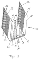
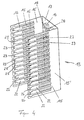
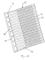
- Figures 3 and 4 show an elongated receptacle 13 of a distribution block 3 of a data signal processing system according to an embodiment of the invention in two different perspective views; the distribution block 3 is provided in this case as a main distributor.
- apparent receptacle 1 are functional elements 14, as for example by way of example in FIG FIG. 3 are shown with their longitudinal direction transversely to the longitudinal direction of the receptacle 13 plugged over one another, whereby the distributor block 3 is formed, by means of which the signals are distributed by connected to the manifold lines in a predetermined manner.
- the receptacle 13 has a continuous U-shaped cross-section and thus two parallel side walls as tub legs 15, 16 and a tub legs 15, 16 perpendicular to the tub bottom 17 through which the tub legs 15, 16 are interconnected.
- the receptacle 13 is preferably made of a sheet metal material, which is easy to bend and which can also be edited well by punching. However, the manner of manufacturing the recesses formed in the tub is not limited to punching; There are also other types of production such as laser processing in question.
- a data signal conditioning unit 18 On the inside of the receptacle is a data signal conditioning unit 18 in the form of an array of active and passive electronic components 19, i. Resistors, coils and coils and the like or semiconductor elements in the form of transistors attached.
- the data signal conditioning unit 18 is thus designed as a so-called splitter filter arrangement, from which a data / data signal bundle frequency-filtered data signals are filtered out and forwarded to the associated transmission destinations.
- These transmission destinations are in a preferred arrangement of the main distributor according to the invention in a telecommunications system, the participants and a telephone switching system and a computer network, by means of which the desired exchange of participants with respect to their voice and computer data is made possible among each other.
- voice data signals emanating from the data signal processing unit 18 and also from the telephone switching system and computer data signals emanating from the computer network are combined to form combined voice data / computer data signals, which are then fed to the subscribers via a common line.
- the data signal conditioning unit 18 has a board 20 with holes 21, via which the board 20 is fixed to the trough bottom 17 of the receptacle 13, for example by means of rivets or screws.
- the components 19 of the data signal conditioning unit 18 are in turn mounted in connection with printed conductors, not shown, standing on the board 20 by means of soldering or plug contacts.
- the trough legs 15, 16 each have a number of holding tongues 22, which are formed, for example, by punching out of the trough legs 15, 16 and which can also serve as connection tongues for distribution-internal connection lines.
- a narrow leg portion 15 ', 16' of the respective trough legs 15, 16 provided as ausOSEungsokoer side wall portion of the receptacle 13, which leg portion 15 ', 16' forms the foot for the associated retaining tabs 22
- the respective retaining tongue 22 has at its free end portion a hole-shaped recess 23 into which a hook 24 of an associated functional element 14 (see FIG.
- the respective holding tongue 22 also has at its free end portion of the recess 23rd adjacent recess 25, which is provided for receiving a wire guide, not shown for wiring wires.
- the recess 25 is for this purpose hook-shaped, so that the wire guide, not shown, can engage with its attachment to the retaining tongue 22 with a corresponding counterpart in the recess 25.
- the recesses 23 of the retaining tongues 22 of in Figures 3 and 4 right and left trough legs 15, 16 are provided in the longitudinal direction of the receptacle 13 seen in opposite directions laterally open.
- the retaining tongues 22 of in Figures 3 are provided in the longitudinal direction of the receptacle 13 seen in opposite directions laterally open.
- 4 right trough legs 15 are further provided at their free end portions with an end-side recess 26, whereas the free end portions of the retaining tongues 22 of the in Figures 3 . 4 left pan legs 16 do not have such a recess.
- the front-side recesses 26 are used to hold guide lugs, not shown, of the functional elements 14, so that the latter can be used only in the correct orientation in the receptacle 13 during assembly of the manifold block.
- the retaining tabs 22 are also at their other end portion, i. her foot section, provided with an elongated tongue longitudinal direction recess 27. These recesses 27 are used to accommodate the side of the receptacle 13 brought up cable connectors (not shown), which in turn are plugged into corresponding receiving sockets on the radio elements 14 for the transmission of data signals. At these cable connectors lines for the interconnection of the functional elements 14 and / or interconnections via printed circuit boards are provided.
- the data signal conditioning unit 18 further comprises a connector part 28 in the form of a socket into which an associated, designed as a plug connector part (not shown) of the functional elements 14 can engage, so as to make electrical contact between the functional element 14 and its internal interconnection and its possibly existing interconnection with other functional elements in a simple manner by inserting this functional element 14 into the receptacle 13 to achieve.
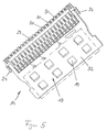
- the end FIG. 5 apparent functional element 14 is provided for receiving copper cables or other stranded cables with a terminal block 29 with a number of insulation displacement terminals 30, in which the copper cables to be connected (not shown) are inserted.
- the insulation displacement terminals 30 are arranged successively in a longitudinal row, with one of the hooks 24 described above being located at the respective front end of the clamping strip 29.
- the insulation displacement terminals 30 are continued downward by contact springs 31, via which a plug contact is achieved with a distribution circuit, not shown.
- the functional element 14 further comprises a second terminal strip, not shown, which is formed according to the above-described terminal block 29 and is arranged parallel to this.
- the signal flow only runs separately in the respective functional elements 14, specifically between the lines which are connected to the two cable strips belonging to the functional element 14.
- a functional element can also have more than two cable strips.
- the interconnections are in the form of integrated in the main distributor cable guides; Alternatively, printed circuit boards are provided with corresponding tracks as interconnections.
- the terminal block 29 and the terminal strip, not shown, are mounted on a printed circuit board 32, on which components 19 of a data signal conditioning unit 18 are mounted.
- the printed circuit board can also be provided on both sides with such components, whereby a space saving is achieved.
- the arrangement of the data signal conditioning unit 18 on the functional element 14 has the advantage that it can be adapted specifically to the associated Verschaltungsplan of the functional element 14 and thus can be placed anywhere in any receptacles 13, without additional votes between conditioning unit 18 and functional element 14th must be made.
- FIGS. 6 and 7 show a cassette element 33 according to the invention of a distribution device of a data signal processing system according to an embodiment of the invention in two different perspective views.
- the cassette member 33 has a printed circuit board 34 on both sides thereof, i. on the front side 34 'and rear side 34' ', in each case components 19 of a data signal conditioning unit 18 as described above are mounted.
- the printed circuit board 34 is enclosed by a frame 35, on which two handles 36 are mounted, which are arranged on mutually opposite frame sections.
- the cassette element 33 is rectangular, with the handles 36 being disposed on the shorter rectangular sides of the frame 35.
- a contact spring strip 37 is provided, which is in electrical connection with the components 19 of the data signal processing system 18 arranged on the printed circuit board 32 and which can be plugged into an associated receiving socket (not shown) on an associated functional element 14, in order to establish an electrical connection between the cassette-side data signal conditioning unit 18 and the interconnection and / or the data signal conditioning unit 18 of the functional element 14 and / or the data signal conditioning unit in the receptacle 13, in which the functional element 14 is accommodated.
- the contact spring strip 37 of the cassette member 33 formed compatible with such a functional element side connector socket, which is otherwise provided for receiving overvoltage / overcurrent protective magazines.
- FIG. 8 a distributor block 3 in the form of an elongated distributor strip 38 according to an embodiment of the invention is shown.
- the distribution strip 38 has an E-profile in cross-section, wherein the two outer strip arms 39, 40 of the distribution strip 38 form thejanselememte 14 are connected to the signal lines, not shown.
- the strip legs 39, 40 on its back on cable terminals on which the signal lines can be attached.
- a middle leg 41 of the E-profiled distribution strip 38 is provided on its front with recesses for receiving individual plugs 42, to which in turn components 19 of a data signal conditioning unit 18 are attached.
- the individual plugs 42 are received in the recesses in exchange for overcurrent / overvoltage protection plug.
- the components 19 of the data signal conditioning unit 18 may also be attached to the busbar by other types of attachment, e.g. by screwing on the middle leg 41.
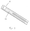
- FIG. 9 an inventive individual connector 42 is shown with a component 19 of a data signal conditioning unit.
- FIG. 10 an alternative to the individual connectors 42 can be seen; Thereafter, a plug cassette 43 is provided, which has a board 44, from which terminal tongues 45 are formed, which can be brought into electrical contact with the distribution strip 38 by the plug cassette 43 is inserted with their connection tabs in the recesses of the distribution strip 38. On the board 44, further components 19 of a data signal conditioning unit 18 are mounted.
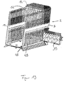
- FIG. 11 another receptacle 13 of a main distributor according to an embodiment of the invention is shown.
- This receptacle 13 differs from the in Figures 3 and 4 shown receptacle 13 in that it has longer tub legs 15, 16, each having two leg portions 46, 47, namely a trough bottom 17 adjacent leg portion 46 and a side facing away from the trough leg region 47.
- the latter are to the tub legs 15, 16 of in Figures 3 . 4 described receptacle substantially identical, so that their description is omitted.
- the armature bottom 17 facing leg portions 46 of the arm legs 15, 16 each have elongated recesses 48 which extend with their longitudinal direction in the direction in which the respective arm legs 15, 16 wegerstreckt from the bottom 17.
- the recesses 48 serve to receive cassette elements 33 which can be introduced into the recesses 48 from the side of the receptacle 13 and can subsequently be inserted into the functional elements 14 arranged in the front region between the leg regions 47 to produce an electrical connection.
- a holder 49 is screwed, which has parallel to the side edge of the trough bottom 17 and thereof outwardly extending strips 50 with slots 51 formed therein for receiving data signal lines, not shown.
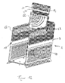
- Figures 12 and 13 show assembly operations when assembling a main distributor according to the invention as a distributor block 3 of a distribution device 2.
- the main distributor has a receptacle 13 according to the basis FIG. 11 described manner, so that reference is made to the above explanations with regard to the construction of the receptacle 13.
- FIG. 13 It can be seen how a cassette element 33 can be inserted from the side of the receiving trough 13 into the associated recess 48. The cassette elements 33 can then be joined together from the rear side of the functional elements 14 to form an electrical contact with the functional elements 14.
- each functional element 14 has a data signal conditioning unit specially assigned to it.
- FIG. 14 schematically shows a distribution device 2 with a manifold block 3 in the form of a main distributor according to an embodiment of the invention.
- the distributor block 3 has a receiving trough 13 with a U-profile, in the trough legs 15, 16 of which slots 53 for receiving functional elements 14 and intermediate plates 54 arranged between them (only one is shown) are formed.
- a data signal conditioning unit 6 with electronic components 19 assigned to the respective functional element 14 is arranged.
- a printed circuit board 55 is arranged between the same and the bottom 17 of the receiving tray 13, which is mated together with the associated functional element 14 electrically connected.
- the printed circuit board 55 may also be a carrier board for receiving electronic components or a data signal conditioning unit; it is electrically connected via a connector strip 56 to a printed circuit board 20 (backplane), which is mounted on the inside of the trough bottom 17.
- a printed circuit board 20 backplane
- conductor tracks are provided on the printed circuit board 55 and the printed circuit board 20, of which an interconnection for the respectively associated functional element 14 is formed.
Landscapes
- Engineering & Computer Science (AREA)
- Computer Networks & Wireless Communication (AREA)
- Structure Of Telephone Exchanges (AREA)
- Communication Control (AREA)
- Radar Systems Or Details Thereof (AREA)
- Devices For Checking Fares Or Tickets At Control Points (AREA)
- Alarm Systems (AREA)
- Cable Transmission Systems, Equalization Of Radio And Reduction Of Echo (AREA)
- Arrangements For Transmission Of Measured Signals (AREA)
- Signal Processing For Digital Recording And Reproducing (AREA)
- Computer And Data Communications (AREA)
Claims (6)
- Dispositif de distribution (2), notamment distributeur principal ou barre de distribution d'une installation de traitement de signaux de données (1), comprenant un bloc de distribution (3), le bloc de distribution (3) présentant des éléments fonctionnels (14) auxquels peuvent être raccordées des lignes de signaux de données (4, 5, 6) et qui présentent une connexion destinée à distribuer les signaux de données transmis au dispositif de distribution (2) par les lignes de signaux de données (4, 5, 6), et le bloc de distribution (3) présentant un dispositif d'accueil dans lequel sont reçus les éléments fonctionnels (14), et une unité de conditionnement de signaux de données (18) comprenant des composants électroniques actifs et/ou passifs (19), l'unité de conditionnement de signaux de données (18) étant intégrée dans les composants du bloc de distribution (3), de telle sorte qu'un ou plusieurs éléments cassettes (33 ; 34) ou éléments enfichables (42), dans lesquels est disposée l'unité de conditionnement de signaux de données (18) ou une partie de celle-ci, puissent être assemblés de manière amovible à des éléments fonctionnels correspondants (14) pour la transmission réciproque de signaux de données par le biais d'une connexion enfichable, qui est réalisée simultanément en tant qu'interface entre l'élément cassette (33, 44) ou l'élément enfichable (42) et l'élément fonctionnel (14), et l'unité de conditionnement de signaux de données (18) conditionnant d'une manière prédéfinie les signaux de données transmis par les lignes de signaux de données de telle sorte que d'une part des signaux de données vocales acheminés au bloc de distribution (3) et des signaux de données de calcul soient assemblés pour donner un signal de données vocales et de données de calcul combiné, et de telle sorte que d'autre part un signal de données vocales et de données de calcul combiné acheminé au bloc de distribution (3) soit divisé en signaux de données vocales et en signaux de données de calcul séparés.
- Dispositif de distribution (2) selon la revendication 1, avec lequel un arrangement de filtrage composé de filtres passe-haut et/ou de filtres passe-bas et/ou de filtres passe-bande est constitué par les composants électroniques (19) de l'unité de conditionnement de signaux de données (18), par lequel les signaux de données transmis par les lignes de signaux de données (6) peuvent être extraits par filtrage et retransmis en fonction de leur plage de fréquences.
- Dispositif de distribution (2) selon la revendication 1, avec lequel l'élément cassette (33, 44) est configuré de manière à pouvoir être raccordé à l'élément fonctionnel (14) en remplacement d'une cartouche de protection contre les surtensions/surintensités et en utilisant son interface.
- Dispositif de distribution (2) selon l'une des revendications 1 à 3, avec lequel les composants électroniques (19) de l'unité de conditionnement de signaux de données (18) ou une partie des composants (19) sont disposés sur une ou plusieurs platines supports qui sont assemblées de manière amovible avec l'élément fonctionnel (14) associé correspondant.
- Dispositif de distribution (2) selon l'une des revendications 1 à 4, avec lequel l'élément fonctionnel (14) correspondant présente un circuit imprimé (24) qui est prévu pour recevoir le ou les composants électroniques (19) de l'unité de conditionnement de signaux de données (18) et sur lequel sont montées des bornes pour le raccordement des lignes de signaux de données (4, 5, 6).
- Installation de traitement de signaux de données comprenant un dispositif de distribution (2) selon l'une des revendications 1 à 5.
Priority Applications (1)
| Application Number | Priority Date | Filing Date | Title |
|---|---|---|---|
| EP04004455A EP1422948A3 (fr) | 2000-06-16 | 2001-06-15 | Dispositif de distribution dans une installation de traitement de signaux de données et installation de traitement de signaux de données |
Applications Claiming Priority (3)
| Application Number | Priority Date | Filing Date | Title |
|---|---|---|---|
| DE10029870 | 2000-06-16 | ||
| DE10029870A DE10029870A1 (de) | 2000-06-16 | 2000-06-16 | Verteilereinrichtung einer Datensignal-Verarbeitungsanlage und Datensignal-Verarbeitungsanlage |
| PCT/DE2001/002227 WO2001097532A2 (fr) | 2000-06-16 | 2001-06-15 | Dispositif de distribution d'une installation de traitement de signaux de donnees et installation de traitement de signaux de donnees |
Related Child Applications (1)
| Application Number | Title | Priority Date | Filing Date |
|---|---|---|---|
| EP04004455A Division EP1422948A3 (fr) | 2000-06-16 | 2001-06-15 | Dispositif de distribution dans une installation de traitement de signaux de données et installation de traitement de signaux de données |
Publications (3)
| Publication Number | Publication Date |
|---|---|
| EP1290901A2 EP1290901A2 (fr) | 2003-03-12 |
| EP1290901B1 EP1290901B1 (fr) | 2004-05-12 |
| EP1290901B2 true EP1290901B2 (fr) | 2009-06-17 |
Family
ID=7646076
Family Applications (2)
| Application Number | Title | Priority Date | Filing Date |
|---|---|---|---|
| EP04004455A Withdrawn EP1422948A3 (fr) | 2000-06-16 | 2001-06-15 | Dispositif de distribution dans une installation de traitement de signaux de données et installation de traitement de signaux de données |
| EP01951385A Expired - Lifetime EP1290901B2 (fr) | 2000-06-16 | 2001-06-15 | Dispositif de distribution d'une installation de traitement de signaux de donnees et installation de traitement de signaux de donnees |
Family Applications Before (1)
| Application Number | Title | Priority Date | Filing Date |
|---|---|---|---|
| EP04004455A Withdrawn EP1422948A3 (fr) | 2000-06-16 | 2001-06-15 | Dispositif de distribution dans une installation de traitement de signaux de données et installation de traitement de signaux de données |
Country Status (9)
| Country | Link |
|---|---|
| US (1) | US7324632B2 (fr) |
| EP (2) | EP1422948A3 (fr) |
| AT (1) | ATE266929T1 (fr) |
| AU (2) | AU2001272338B2 (fr) |
| DE (2) | DE10029870A1 (fr) |
| ES (1) | ES2220784T5 (fr) |
| PT (1) | PT1290901E (fr) |
| TR (1) | TR200401999T4 (fr) |
| WO (1) | WO2001097532A2 (fr) |
Families Citing this family (28)
| Publication number | Priority date | Publication date | Assignee | Title |
|---|---|---|---|---|
| DE10029870A1 (de) | 2000-06-16 | 2002-01-03 | Rxs Kabelgarnituren Gmbh & Co | Verteilereinrichtung einer Datensignal-Verarbeitungsanlage und Datensignal-Verarbeitungsanlage |
| DE20104605U1 (de) | 2001-03-16 | 2001-05-31 | 3M Innovative Properties Co | Anschlussblock und Verteilereinrichtung |
| US7257223B2 (en) | 2001-05-10 | 2007-08-14 | Adc Telecommunications, Inc. | Splitter assembly for a telecommunications system |
| US6804353B2 (en) | 2001-06-29 | 2004-10-12 | Adc Telecommunications, Inc. | Splitter assembly with high density backplane board |
| US6738463B2 (en) | 2001-06-29 | 2004-05-18 | Adc Telecommunications, Inc. | Splitter assembly with inverted pots and line connectors |
| US6804352B2 (en) * | 2001-06-29 | 2004-10-12 | Adc Telecommunications, Inc. | High circuit density pots splitter assembly |
| US6628525B2 (en) | 2001-06-29 | 2003-09-30 | Adc Telecommunications, Inc. | Card guide for a telecommunications splitter assembly |
| DE20203910U1 (de) | 2002-03-11 | 2003-07-17 | 3M Innovative Properties Co | Anschlussmodul der Telekommunikationstechnik |
| DE10231039A1 (de) * | 2002-07-09 | 2004-01-22 | CCS Technology, Inc., Wilmington | Verteilersystem einer Telekommunikationsanlage |
| ITTO20020178U1 (it) * | 2002-10-04 | 2004-04-05 | Urmet Sistemi S P A | Sistema di moduli filtro pots-splitter per adsl. |
| EP1455418A1 (fr) * | 2003-03-03 | 2004-09-08 | 3M Innovative Properties Company | Module de télécommunication |
| EP1455417A1 (fr) * | 2003-03-03 | 2004-09-08 | 3M Innovative Properties Company | Module fonctionnel pour montage dans un module de télécommunication et méthode d'installation du module de télécommunication |
| DE10331564A1 (de) * | 2003-07-11 | 2005-02-10 | Siemens Ag | Aufsteckbarer Splitter für eine Trennleiste |
| DE20315191U1 (de) * | 2003-09-30 | 2003-12-04 | CCS Technology, Inc., Wilmington | Splittereinrichtung für eine Verteilereinrichtung einer Telekommunikationsanlage |
| DE602004023268D1 (de) * | 2004-03-18 | 2009-11-05 | 3M Innovative Properties Co | Schaltung und Verfahren für den Zugang zu einem Test und/oder Überwachungssystem |
| EP1679766A1 (fr) * | 2005-01-10 | 2006-07-12 | 3M Innovative Properties Company | Plaque guide-fil et son assemblage ainsi qu'un module de télécommunication comprenant au moins une plaque guide-fil |
| EP1699117A1 (fr) * | 2005-03-04 | 2006-09-06 | 3M Innovative Properties Company | Module de télécommunication, dispositif de modules de télécommunication et au moins un module extrene, procédé de fabrication d'un module de télécommunication et l'utilisation d'un module de télécommunication |
| US20070031801A1 (en) * | 2005-06-16 | 2007-02-08 | Ctb Mcgraw Hill | Patterned response system and method |
| US20070082522A1 (en) * | 2005-10-11 | 2007-04-12 | Pierre Bonvallat | Carrier and an assembly including a carrier and a telecommunications module |
| US7652889B2 (en) * | 2005-10-25 | 2010-01-26 | Hewlett-Packard Development Company, L.P. | Information technology (IT) equipment position locating system using jumper connections |
| DE202006005683U1 (de) * | 2006-04-05 | 2006-07-20 | CCS Technology, Inc., Wilmington | Verteilereinrichtung einer Telekommunikatiosanlage |
| DE202006016752U1 (de) * | 2006-10-30 | 2007-02-01 | CCS Technology, Inc., Wilmington | Verteilereinrichtung einer Telekommunikationsanlage |
| DE202007001344U1 (de) * | 2007-01-24 | 2007-04-05 | CCS Technology, Inc., Wilmington | Verteilereinrichtung einer Telekommunikationsanlage |
| DE202007014702U1 (de) * | 2007-10-18 | 2007-12-27 | Ccs Technology Inc., Wilmington | Verteilereinrichtung einer Telekommunikationsanlage sowie Stecker für eine Verteilereinrichtung einer Telekommunikationsanlage |
| DE202008004035U1 (de) | 2008-03-20 | 2008-05-21 | CCS Technology, Inc., Wilmington | Verteilereinrichtung einer Telekommunikationsanlage sowie Verteilerleiste einer Verteilereinrichtung |
| EP2804392A1 (fr) | 2013-05-17 | 2014-11-19 | 3M Innovative Properties Company | Module de terminaison |
| DE102015223222A1 (de) | 2015-11-24 | 2017-05-24 | Commscope Technologies Llc | Splittereinrichtung und Anordnung |
| DE202018105412U1 (de) | 2018-09-20 | 2018-11-12 | Corning Optical Communications LLC | Verteilereinrichtung einer Telekommunikationsanlage |
Family Cites Families (20)
| Publication number | Priority date | Publication date | Assignee | Title |
|---|---|---|---|---|
| DE2048104C3 (de) | 1970-09-30 | 1979-04-05 | Siemens Ag, 1000 Berlin Und 8000 Muenchen | Verteilerleiste für elektrische Anlagen, insbesondere Fernsprechanlagen |
| GB2060267A (en) * | 1979-10-08 | 1981-04-29 | Teletechnique Moderne Comp | Cable head with protection for a telephone exchange distributor |
| US4470127A (en) * | 1981-05-18 | 1984-09-04 | Texas Instruments Incorporated | Data terminal with error checking file transfer mode |
| AU4892485A (en) | 1984-10-26 | 1986-05-01 | Adc Telecommunications, Incorporated | Modular distribution frame |
| US4766521A (en) * | 1987-05-22 | 1988-08-23 | Northern Telecom Limited | Connecting blocks for telephone systems |
| US4763226A (en) * | 1987-05-22 | 1988-08-09 | Northern Telecom Limited | Connecting blocks and mounting arrangements for telephone systems |
| DE3836360A1 (de) * | 1988-10-21 | 1990-04-26 | Krone Ag | Verteilereinrichtung, insbesondere fuer den hauptverteiler von fernsprechanlagen |
| DE3842904A1 (de) * | 1988-12-16 | 1990-06-21 | Siemens Ag | Anordnung mit mehreren spleissmodulen |
| US4975072A (en) * | 1989-10-25 | 1990-12-04 | Telect, Inc. | Front facing terminal block for telecommunication main distribution frame |
| FR2688370B1 (fr) * | 1992-03-03 | 1994-05-27 | Yves Saligny | Element de repartiteur telephonique, en particulier reglette. |
| DE4306349C1 (de) * | 1993-02-23 | 1994-03-17 | Krone Ag | Verteilereinrichtung, insbesondere für den Hauptverteiler von Fernsprech- und Datenleitungen |
| US5544004A (en) * | 1993-10-14 | 1996-08-06 | Nippon Telegraph And Telephone Corporation | Pin-board matrix switch |
| US5668857A (en) * | 1996-03-29 | 1997-09-16 | Netspeed, Inc. | Communication server apparatus and method |
| US5930340A (en) * | 1997-07-07 | 1999-07-27 | Advanced Micro Devices | Device and method for isolating voice and data signals on a common carrier |
| US6314102B1 (en) | 1997-07-10 | 2001-11-06 | Alcatel | Telecommunications system for providing both narrowband and broadband services to subscribers |
| US6438226B1 (en) | 1997-10-06 | 2002-08-20 | Ccs Holdings, Inc. | XDSL splitter assembly for main distribution frame |
| US6272219B1 (en) | 1998-04-01 | 2001-08-07 | Terayon Communications Systems, Inc. | Access network with an integrated splitter |
| US6137866A (en) * | 1998-05-28 | 2000-10-24 | Siecor Operations, Llc | Indoor XDSL splitter assembly |
| DE10029649C9 (de) | 2000-06-15 | 2008-02-07 | Adc Gmbh | Verteileranschlußmodul für die Telekommunikations- und Datentechnik |
| DE10029870A1 (de) | 2000-06-16 | 2002-01-03 | Rxs Kabelgarnituren Gmbh & Co | Verteilereinrichtung einer Datensignal-Verarbeitungsanlage und Datensignal-Verarbeitungsanlage |
-
2000
- 2000-06-16 DE DE10029870A patent/DE10029870A1/de not_active Withdrawn
-
2001
- 2001-06-15 EP EP04004455A patent/EP1422948A3/fr not_active Withdrawn
- 2001-06-15 DE DE50102275T patent/DE50102275D1/de not_active Expired - Lifetime
- 2001-06-15 ES ES01951385T patent/ES2220784T5/es not_active Expired - Lifetime
- 2001-06-15 EP EP01951385A patent/EP1290901B2/fr not_active Expired - Lifetime
- 2001-06-15 AT AT01951385T patent/ATE266929T1/de active
- 2001-06-15 TR TR2004/01999T patent/TR200401999T4/xx unknown
- 2001-06-15 WO PCT/DE2001/002227 patent/WO2001097532A2/fr active IP Right Grant
- 2001-06-15 AU AU2001272338A patent/AU2001272338B2/en not_active Ceased
- 2001-06-15 PT PT01951385T patent/PT1290901E/pt unknown
- 2001-06-15 US US10/311,197 patent/US7324632B2/en not_active Expired - Fee Related
- 2001-06-15 AU AU7233801A patent/AU7233801A/xx active Pending
Also Published As
| Publication number | Publication date |
|---|---|
| EP1290901B1 (fr) | 2004-05-12 |
| ES2220784T3 (es) | 2004-12-16 |
| EP1290901A2 (fr) | 2003-03-12 |
| EP1422948A2 (fr) | 2004-05-26 |
| WO2001097532A2 (fr) | 2001-12-20 |
| WO2001097532A3 (fr) | 2002-06-27 |
| TR200401999T4 (tr) | 2004-09-21 |
| US20040022013A1 (en) | 2004-02-05 |
| PT1290901E (pt) | 2004-09-30 |
| DE10029870A1 (de) | 2002-01-03 |
| AU7233801A (en) | 2001-12-24 |
| EP1422948A3 (fr) | 2004-09-22 |
| AU2001272338B2 (en) | 2006-09-14 |
| ES2220784T5 (es) | 2009-11-11 |
| ATE266929T1 (de) | 2004-05-15 |
| US7324632B2 (en) | 2008-01-29 |
| DE50102275D1 (de) | 2004-06-17 |
Similar Documents
| Publication | Publication Date | Title |
|---|---|---|
| EP1290901B2 (fr) | Dispositif de distribution d'une installation de traitement de signaux de donnees et installation de traitement de signaux de donnees | |
| DE4402002B4 (de) | E/A-Module/ für einen Datenbus | |
| DE10029649C5 (de) | Verteileranschlußmodul für die Telekommunikations- und Datentechnik | |
| EP0243296B1 (fr) | Dispositif de répartition, en particulier pour le répartiteur principal d'installations de télécommunication | |
| DE112009000669B4 (de) | Verbindungsmodul | |
| EP3631922B1 (fr) | Tableau de distribution | |
| DE2351653A1 (de) | Elektrische kabelverbindung | |
| EP0952635B1 (fr) | Connecteur électrique | |
| EP0461454B1 (fr) | Dispositif de distribution | |
| DE4306349C1 (de) | Verteilereinrichtung, insbesondere für den Hauptverteiler von Fernsprech- und Datenleitungen | |
| DE4210657C2 (de) | Einschub-Niederspannungsschaltanlage zur Abgabe oder Verteilung elektrischer Energie | |
| DE3836668C1 (fr) | ||
| EP1897382B1 (fr) | Dispositif de repartition d'une installation de telecommunication | |
| DE19816391C2 (de) | Türstation einer Türsprechanlage | |
| EP0865119B1 (fr) | Boíte de connexion pour un système de distribution | |
| DE4440602C2 (de) | Einrichtung zum Sichern von elektrischen Leitungen | |
| WO2012152300A1 (fr) | Module de répartition de connexions | |
| EP1232654B1 (fr) | Module de connexion cote systeme et repartiteur faisant partie de la technologie des telecommunications | |
| EP2073314B1 (fr) | Agencement de liaison électrique conductrice des conducteurs électriques | |
| DE20122214U1 (de) | Verteilereinrichtung einer Datensignal-Verarbeitungsanlage und Datensignal-Verarbeitungsanlage | |
| DE20023395U1 (de) | Verteilereinrichtung einer Datensignal-Verarbeitungsanlage und Datensignal-Verarbeitungsanlage | |
| EP4277248A1 (fr) | Support de module destiné à recevoir un module pour installations de porte, unité de module et installation de porte | |
| DE69733120T2 (de) | Zwischenkopplung | |
| DE69937325T2 (de) | Elektrischer Verbinder für eine gedruckte Schaltung | |
| EP2597887A1 (fr) | Module de raccordement |
Legal Events
| Date | Code | Title | Description |
|---|---|---|---|
| PUAI | Public reference made under article 153(3) epc to a published international application that has entered the european phase |
Free format text: ORIGINAL CODE: 0009012 |
|
| 17P | Request for examination filed |
Effective date: 20021203 |
|
| AK | Designated contracting states |
Kind code of ref document: A2 Designated state(s): AT BE CH CY DE DK ES FI FR GB GR IE IT LI LU MC NL PT SE TR |
|
| RIN1 | Information on inventor provided before grant (corrected) |
Inventor name: BREUER, MIKE Inventor name: BADURA, STEFAN Inventor name: ZIMMER, RAINER Inventor name: CZINGON, RALF |
|
| GRAP | Despatch of communication of intention to grant a patent |
Free format text: ORIGINAL CODE: EPIDOSNIGR1 |
|
| GRAS | Grant fee paid |
Free format text: ORIGINAL CODE: EPIDOSNIGR3 |
|
| GRAA | (expected) grant |
Free format text: ORIGINAL CODE: 0009210 |
|
| AK | Designated contracting states |
Kind code of ref document: B1 Designated state(s): AT BE CH CY DE DK ES FI FR GB GR IE IT LI LU MC NL PT SE TR |
|
| PG25 | Lapsed in a contracting state [announced via postgrant information from national office to epo] |
Ref country code: CY Free format text: LAPSE BECAUSE OF FAILURE TO SUBMIT A TRANSLATION OF THE DESCRIPTION OR TO PAY THE FEE WITHIN THE PRESCRIBED TIME-LIMIT Effective date: 20040512 |
|
| REG | Reference to a national code |
Ref country code: GB Ref legal event code: FG4D Free format text: NOT ENGLISH |
|
| REG | Reference to a national code |
Ref country code: CH Ref legal event code: EP |
|
| PG25 | Lapsed in a contracting state [announced via postgrant information from national office to epo] |
Ref country code: LU Free format text: LAPSE BECAUSE OF NON-PAYMENT OF DUE FEES Effective date: 20040615 |
|
| REG | Reference to a national code |
Ref country code: IE Ref legal event code: FG4D Free format text: GERMAN |
|
| REF | Corresponds to: |
Ref document number: 50102275 Country of ref document: DE Date of ref document: 20040617 Kind code of ref document: P |
|
| PG25 | Lapsed in a contracting state [announced via postgrant information from national office to epo] |
Ref country code: MC Free format text: LAPSE BECAUSE OF NON-PAYMENT OF DUE FEES Effective date: 20040630 |
|
| PG25 | Lapsed in a contracting state [announced via postgrant information from national office to epo] |
Ref country code: DK Free format text: LAPSE BECAUSE OF FAILURE TO SUBMIT A TRANSLATION OF THE DESCRIPTION OR TO PAY THE FEE WITHIN THE PRESCRIBED TIME-LIMIT Effective date: 20040812 |
|
| REG | Reference to a national code |
Ref country code: SE Ref legal event code: TRGR |
|
| GBT | Gb: translation of ep patent filed (gb section 77(6)(a)/1977) |
Effective date: 20040813 |
|
| REG | Reference to a national code |
Ref country code: PT Ref legal event code: SC4A Free format text: AVAILABILITY OF NATIONAL TRANSLATION Effective date: 20040730 |
|
| REG | Reference to a national code |
Ref country code: GR Ref legal event code: EP Ref document number: 20040402786 Country of ref document: GR |
|
| REG | Reference to a national code |
Ref country code: ES Ref legal event code: FG2A Ref document number: 2220784 Country of ref document: ES Kind code of ref document: T3 |
|
| ET | Fr: translation filed | ||
| PLAQ | Examination of admissibility of opposition: information related to despatch of communication + time limit deleted |
Free format text: ORIGINAL CODE: EPIDOSDOPE2 |
|
| PLBQ | Unpublished change to opponent data |
Free format text: ORIGINAL CODE: EPIDOS OPPO |
|
| PLBI | Opposition filed |
Free format text: ORIGINAL CODE: 0009260 |
|
| PLAQ | Examination of admissibility of opposition: information related to despatch of communication + time limit deleted |
Free format text: ORIGINAL CODE: EPIDOSDOPE2 |
|
| PLAR | Examination of admissibility of opposition: information related to receipt of reply deleted |
Free format text: ORIGINAL CODE: EPIDOSDOPE4 |
|
| PLBQ | Unpublished change to opponent data |
Free format text: ORIGINAL CODE: EPIDOS OPPO |
|
| PLAB | Opposition data, opponent's data or that of the opponent's representative modified |
Free format text: ORIGINAL CODE: 0009299OPPO |
|
| PLBI | Opposition filed |
Free format text: ORIGINAL CODE: 0009260 |
|
| PLAX | Notice of opposition and request to file observation + time limit sent |
Free format text: ORIGINAL CODE: EPIDOSNOBS2 |
|
| 26 | Opposition filed |
Opponent name: KRONE GMBH Effective date: 20050210 |
|
| 26 | Opposition filed |
Opponent name: KRONE GMBH Effective date: 20050210 Opponent name: VACUUMSCHMELZE GMBH & CO. KG Effective date: 20050211 |
|
| NLR1 | Nl: opposition has been filed with the epo |
Opponent name: KRONE GMBH Opponent name: VACUUMSCHMELZE GMBH & CO. KG |
|
| PLBB | Reply of patent proprietor to notice(s) of opposition received |
Free format text: ORIGINAL CODE: EPIDOSNOBS3 |
|
| PLAB | Opposition data, opponent's data or that of the opponent's representative modified |
Free format text: ORIGINAL CODE: 0009299OPPO |
|
| R26 | Opposition filed (corrected) |
Opponent name: ADC BETEILIGUNGSGESELLSCHAFT MBH Effective date: 20050210 Opponent name: VACUUMSCHMELZE GMBH & CO. KG Effective date: 20050211 |
|
| NLR1 | Nl: opposition has been filed with the epo |
Opponent name: VACUUMSCHMELZE GMBH & CO. KG Opponent name: ADC BETEILIGUNGSGESELLSCHAFT MBH |
|
| PLAY | Examination report in opposition despatched + time limit |
Free format text: ORIGINAL CODE: EPIDOSNORE2 |
|
| APBM | Appeal reference recorded |
Free format text: ORIGINAL CODE: EPIDOSNREFNO |
|
| APBP | Date of receipt of notice of appeal recorded |
Free format text: ORIGINAL CODE: EPIDOSNNOA2O |
|
| PLAP | Information related to despatch of examination report in opposition + time limit deleted |
Free format text: ORIGINAL CODE: EPIDOSDORE2 |
|
| APBQ | Date of receipt of statement of grounds of appeal recorded |
Free format text: ORIGINAL CODE: EPIDOSNNOA3O |
|
| APAH | Appeal reference modified |
Free format text: ORIGINAL CODE: EPIDOSCREFNO |
|
| APBU | Appeal procedure closed |
Free format text: ORIGINAL CODE: EPIDOSNNOA9O |
|
| PLBP | Opposition withdrawn |
Free format text: ORIGINAL CODE: 0009264 |
|
| PLAB | Opposition data, opponent's data or that of the opponent's representative modified |
Free format text: ORIGINAL CODE: 0009299OPPO |
|
| PUAH | Patent maintained in amended form |
Free format text: ORIGINAL CODE: 0009272 |
|
| STAA | Information on the status of an ep patent application or granted ep patent |
Free format text: STATUS: PATENT MAINTAINED AS AMENDED |
|
| 27A | Patent maintained in amended form |
Effective date: 20090617 |
|
| AK | Designated contracting states |
Kind code of ref document: B2 Designated state(s): AT BE CH CY DE DK ES FI FR GB GR IE IT LI LU MC NL PT SE TR |
|
| REG | Reference to a national code |
Ref country code: CH Ref legal event code: AEN Free format text: AUFRECHTERHALTUNG DES PATENTES IN GEAENDERTER FORM |
|
| NLR2 | Nl: decision of opposition |
Effective date: 20090617 |
|
| REG | Reference to a national code |
Ref country code: SE Ref legal event code: RPEO |
|
| REG | Reference to a national code |
Ref country code: GR Ref legal event code: EP Ref document number: 20090402327 Country of ref document: GR |
|
| NLR3 | Nl: receipt of modified translations in the netherlands language after an opposition procedure | ||
| REG | Reference to a national code |
Ref country code: ES Ref legal event code: DC2A Date of ref document: 20090903 Kind code of ref document: T5 |
|
| REG | Reference to a national code |
Ref country code: FR Ref legal event code: PLFP Year of fee payment: 15 |
|
| PGFP | Annual fee paid to national office [announced via postgrant information from national office to epo] |
Ref country code: FI Payment date: 20150629 Year of fee payment: 15 Ref country code: PT Payment date: 20150520 Year of fee payment: 15 Ref country code: TR Payment date: 20150602 Year of fee payment: 15 Ref country code: SE Payment date: 20150629 Year of fee payment: 15 |
|
| PGFP | Annual fee paid to national office [announced via postgrant information from national office to epo] |
Ref country code: IE Payment date: 20150630 Year of fee payment: 15 Ref country code: GR Payment date: 20150629 Year of fee payment: 15 |
|
| REG | Reference to a national code |
Ref country code: FR Ref legal event code: PLFP Year of fee payment: 16 |
|
| PG25 | Lapsed in a contracting state [announced via postgrant information from national office to epo] |
Ref country code: FI Free format text: LAPSE BECAUSE OF NON-PAYMENT OF DUE FEES Effective date: 20160615 |
|
| REG | Reference to a national code |
Ref country code: SE Ref legal event code: EUG |
|
| PG25 | Lapsed in a contracting state [announced via postgrant information from national office to epo] |
Ref country code: PT Free format text: LAPSE BECAUSE OF NON-PAYMENT OF DUE FEES Effective date: 20161215 Ref country code: SE Free format text: LAPSE BECAUSE OF NON-PAYMENT OF DUE FEES Effective date: 20160616 |
|
| REG | Reference to a national code |
Ref country code: GR Ref legal event code: ML Ref document number: 20090402327 Country of ref document: GR Effective date: 20170109 |
|
| REG | Reference to a national code |
Ref country code: IE Ref legal event code: MM4A |
|
| PG25 | Lapsed in a contracting state [announced via postgrant information from national office to epo] |
Ref country code: GR Free format text: LAPSE BECAUSE OF NON-PAYMENT OF DUE FEES Effective date: 20170109 |
|
| PG25 | Lapsed in a contracting state [announced via postgrant information from national office to epo] |
Ref country code: IE Free format text: LAPSE BECAUSE OF NON-PAYMENT OF DUE FEES Effective date: 20160615 |
|
| REG | Reference to a national code |
Ref country code: FR Ref legal event code: PLFP Year of fee payment: 17 |
|
| PGFP | Annual fee paid to national office [announced via postgrant information from national office to epo] |
Ref country code: FR Payment date: 20170627 Year of fee payment: 17 Ref country code: CH Payment date: 20170627 Year of fee payment: 17 Ref country code: GB Payment date: 20170627 Year of fee payment: 17 |
|
| PGFP | Annual fee paid to national office [announced via postgrant information from national office to epo] |
Ref country code: IT Payment date: 20170622 Year of fee payment: 17 Ref country code: BE Payment date: 20170627 Year of fee payment: 17 Ref country code: NL Payment date: 20170626 Year of fee payment: 17 Ref country code: AT Payment date: 20170519 Year of fee payment: 17 |
|
| PGFP | Annual fee paid to national office [announced via postgrant information from national office to epo] |
Ref country code: DE Payment date: 20170628 Year of fee payment: 17 Ref country code: ES Payment date: 20170705 Year of fee payment: 17 |
|
| REG | Reference to a national code |
Ref country code: DE Ref legal event code: R119 Ref document number: 50102275 Country of ref document: DE |
|
| REG | Reference to a national code |
Ref country code: CH Ref legal event code: PL |
|
| REG | Reference to a national code |
Ref country code: NL Ref legal event code: MM Effective date: 20180701 |
|
| REG | Reference to a national code |
Ref country code: AT Ref legal event code: MM01 Ref document number: 266929 Country of ref document: AT Kind code of ref document: T Effective date: 20180615 |
|
| GBPC | Gb: european patent ceased through non-payment of renewal fee |
Effective date: 20180615 |
|
| REG | Reference to a national code |
Ref country code: BE Ref legal event code: MM Effective date: 20180630 |
|
| PG25 | Lapsed in a contracting state [announced via postgrant information from national office to epo] |
Ref country code: NL Free format text: LAPSE BECAUSE OF NON-PAYMENT OF DUE FEES Effective date: 20180701 |
|
| PG25 | Lapsed in a contracting state [announced via postgrant information from national office to epo] |
Ref country code: DE Free format text: LAPSE BECAUSE OF NON-PAYMENT OF DUE FEES Effective date: 20190101 Ref country code: GB Free format text: LAPSE BECAUSE OF NON-PAYMENT OF DUE FEES Effective date: 20180615 Ref country code: AT Free format text: LAPSE BECAUSE OF NON-PAYMENT OF DUE FEES Effective date: 20180615 Ref country code: CH Free format text: LAPSE BECAUSE OF NON-PAYMENT OF DUE FEES Effective date: 20180630 Ref country code: LI Free format text: LAPSE BECAUSE OF NON-PAYMENT OF DUE FEES Effective date: 20180630 Ref country code: FR Free format text: LAPSE BECAUSE OF NON-PAYMENT OF DUE FEES Effective date: 20180630 Ref country code: IT Free format text: LAPSE BECAUSE OF NON-PAYMENT OF DUE FEES Effective date: 20180615 |
|
| PG25 | Lapsed in a contracting state [announced via postgrant information from national office to epo] |
Ref country code: BE Free format text: LAPSE BECAUSE OF NON-PAYMENT OF DUE FEES Effective date: 20180630 |
|
| REG | Reference to a national code |
Ref country code: ES Ref legal event code: FD2A Effective date: 20190916 |
|
| PG25 | Lapsed in a contracting state [announced via postgrant information from national office to epo] |
Ref country code: ES Free format text: LAPSE BECAUSE OF NON-PAYMENT OF DUE FEES Effective date: 20180616 |
|
| PG25 | Lapsed in a contracting state [announced via postgrant information from national office to epo] |
Ref country code: TR Free format text: LAPSE BECAUSE OF NON-PAYMENT OF DUE FEES Effective date: 20160615 |