EP1289639B1 - Dosiereinrichtung - Google Patents
Dosiereinrichtung Download PDFInfo
- Publication number
- EP1289639B1 EP1289639B1 EP01941306A EP01941306A EP1289639B1 EP 1289639 B1 EP1289639 B1 EP 1289639B1 EP 01941306 A EP01941306 A EP 01941306A EP 01941306 A EP01941306 A EP 01941306A EP 1289639 B1 EP1289639 B1 EP 1289639B1
- Authority
- EP
- European Patent Office
- Prior art keywords
- additive
- dosing
- container
- inlet
- weighing means
- Prior art date
- Legal status (The legal status is an assumption and is not a legal conclusion. Google has not performed a legal analysis and makes no representation as to the accuracy of the status listed.)
- Expired - Lifetime
Links
- 239000000654 additive Substances 0.000 claims abstract description 43
- 230000000996 additive effect Effects 0.000 claims abstract description 43
- 230000007246 mechanism Effects 0.000 claims abstract description 24
- 238000005303 weighing Methods 0.000 claims abstract description 24
- 230000005484 gravity Effects 0.000 claims description 8
- 238000005259 measurement Methods 0.000 description 8
- 238000010276 construction Methods 0.000 description 6
- 239000000463 material Substances 0.000 description 6
- 238000013016 damping Methods 0.000 description 5
- 230000003466 anti-cipated effect Effects 0.000 description 2
- 230000008859 change Effects 0.000 description 2
- 238000006073 displacement reaction Methods 0.000 description 2
- 238000000034 method Methods 0.000 description 2
- 230000008569 process Effects 0.000 description 2
- 239000002994 raw material Substances 0.000 description 2
- 230000009471 action Effects 0.000 description 1
- 230000002411 adverse Effects 0.000 description 1
- 230000001419 dependent effect Effects 0.000 description 1
- 230000000694 effects Effects 0.000 description 1
- 238000002474 experimental method Methods 0.000 description 1
- 238000001125 extrusion Methods 0.000 description 1
- 230000002349 favourable effect Effects 0.000 description 1
- 239000000945 filler Substances 0.000 description 1
- 239000012530 fluid Substances 0.000 description 1
- 238000001746 injection moulding Methods 0.000 description 1
- 239000000203 mixture Substances 0.000 description 1
- 230000004044 response Effects 0.000 description 1
- XLYOFNOQVPJJNP-UHFFFAOYSA-N water Substances O XLYOFNOQVPJJNP-UHFFFAOYSA-N 0.000 description 1
Images
Classifications
-
- B—PERFORMING OPERATIONS; TRANSPORTING
- B01—PHYSICAL OR CHEMICAL PROCESSES OR APPARATUS IN GENERAL
- B01F—MIXING, e.g. DISSOLVING, EMULSIFYING OR DISPERSING
- B01F35/00—Accessories for mixers; Auxiliary operations or auxiliary devices; Parts or details of general application
- B01F35/80—Forming a predetermined ratio of the substances to be mixed
- B01F35/88—Forming a predetermined ratio of the substances to be mixed by feeding the materials batchwise
- B01F35/881—Forming a predetermined ratio of the substances to be mixed by feeding the materials batchwise by weighing, e.g. with automatic discharge
-
- B—PERFORMING OPERATIONS; TRANSPORTING
- B01—PHYSICAL OR CHEMICAL PROCESSES OR APPARATUS IN GENERAL
- B01F—MIXING, e.g. DISSOLVING, EMULSIFYING OR DISPERSING
- B01F25/00—Flow mixers; Mixers for falling materials, e.g. solid particles
- B01F25/80—Falling particle mixers, e.g. with repeated agitation along a vertical axis
- B01F25/90—Falling particle mixers, e.g. with repeated agitation along a vertical axis with moving or vibrating means, e.g. stirrers, for enhancing the mixing
-
- B—PERFORMING OPERATIONS; TRANSPORTING
- B01—PHYSICAL OR CHEMICAL PROCESSES OR APPARATUS IN GENERAL
- B01F—MIXING, e.g. DISSOLVING, EMULSIFYING OR DISPERSING
- B01F35/00—Accessories for mixers; Auxiliary operations or auxiliary devices; Parts or details of general application
- B01F35/71—Feed mechanisms
- B01F35/714—Feed mechanisms for feeding predetermined amounts
-
- B—PERFORMING OPERATIONS; TRANSPORTING
- B01—PHYSICAL OR CHEMICAL PROCESSES OR APPARATUS IN GENERAL
- B01F—MIXING, e.g. DISSOLVING, EMULSIFYING OR DISPERSING
- B01F35/00—Accessories for mixers; Auxiliary operations or auxiliary devices; Parts or details of general application
- B01F35/71—Feed mechanisms
- B01F35/717—Feed mechanisms characterised by the means for feeding the components to the mixer
- B01F35/7173—Feed mechanisms characterised by the means for feeding the components to the mixer using gravity, e.g. from a hopper
-
- B—PERFORMING OPERATIONS; TRANSPORTING
- B01—PHYSICAL OR CHEMICAL PROCESSES OR APPARATUS IN GENERAL
- B01F—MIXING, e.g. DISSOLVING, EMULSIFYING OR DISPERSING
- B01F35/00—Accessories for mixers; Auxiliary operations or auxiliary devices; Parts or details of general application
- B01F35/71—Feed mechanisms
- B01F35/717—Feed mechanisms characterised by the means for feeding the components to the mixer
- B01F35/71775—Feed mechanisms characterised by the means for feeding the components to the mixer using helical screws
-
- B—PERFORMING OPERATIONS; TRANSPORTING
- B29—WORKING OF PLASTICS; WORKING OF SUBSTANCES IN A PLASTIC STATE IN GENERAL
- B29B—PREPARATION OR PRETREATMENT OF THE MATERIAL TO BE SHAPED; MAKING GRANULES OR PREFORMS; RECOVERY OF PLASTICS OR OTHER CONSTITUENTS OF WASTE MATERIAL CONTAINING PLASTICS
- B29B7/00—Mixing; Kneading
- B29B7/30—Mixing; Kneading continuous, with mechanical mixing or kneading devices
- B29B7/58—Component parts, details or accessories; Auxiliary operations
- B29B7/60—Component parts, details or accessories; Auxiliary operations for feeding, e.g. end guides for the incoming material
-
- B—PERFORMING OPERATIONS; TRANSPORTING
- B29—WORKING OF PLASTICS; WORKING OF SUBSTANCES IN A PLASTIC STATE IN GENERAL
- B29B—PREPARATION OR PRETREATMENT OF THE MATERIAL TO BE SHAPED; MAKING GRANULES OR PREFORMS; RECOVERY OF PLASTICS OR OTHER CONSTITUENTS OF WASTE MATERIAL CONTAINING PLASTICS
- B29B7/00—Mixing; Kneading
- B29B7/30—Mixing; Kneading continuous, with mechanical mixing or kneading devices
- B29B7/58—Component parts, details or accessories; Auxiliary operations
- B29B7/72—Measuring, controlling or regulating
- B29B7/728—Measuring data of the driving system, e.g. torque, speed, power, vibration
-
- B—PERFORMING OPERATIONS; TRANSPORTING
- B29—WORKING OF PLASTICS; WORKING OF SUBSTANCES IN A PLASTIC STATE IN GENERAL
- B29B—PREPARATION OR PRETREATMENT OF THE MATERIAL TO BE SHAPED; MAKING GRANULES OR PREFORMS; RECOVERY OF PLASTICS OR OTHER CONSTITUENTS OF WASTE MATERIAL CONTAINING PLASTICS
- B29B7/00—Mixing; Kneading
- B29B7/80—Component parts, details or accessories; Auxiliary operations
- B29B7/88—Adding charges, i.e. additives
-
- B—PERFORMING OPERATIONS; TRANSPORTING
- B29—WORKING OF PLASTICS; WORKING OF SUBSTANCES IN A PLASTIC STATE IN GENERAL
- B29C—SHAPING OR JOINING OF PLASTICS; SHAPING OF MATERIAL IN A PLASTIC STATE, NOT OTHERWISE PROVIDED FOR; AFTER-TREATMENT OF THE SHAPED PRODUCTS, e.g. REPAIRING
- B29C45/00—Injection moulding, i.e. forcing the required volume of moulding material through a nozzle into a closed mould; Apparatus therefor
- B29C45/17—Component parts, details or accessories; Auxiliary operations
- B29C45/18—Feeding the material into the injection moulding apparatus, i.e. feeding the non-plastified material into the injection unit
- B29C45/1816—Feeding auxiliary material, e.g. colouring material
-
- B—PERFORMING OPERATIONS; TRANSPORTING
- B29—WORKING OF PLASTICS; WORKING OF SUBSTANCES IN A PLASTIC STATE IN GENERAL
- B29C—SHAPING OR JOINING OF PLASTICS; SHAPING OF MATERIAL IN A PLASTIC STATE, NOT OTHERWISE PROVIDED FOR; AFTER-TREATMENT OF THE SHAPED PRODUCTS, e.g. REPAIRING
- B29C48/00—Extrusion moulding, i.e. expressing the moulding material through a die or nozzle which imparts the desired form; Apparatus therefor
- B29C48/25—Component parts, details or accessories; Auxiliary operations
- B29C48/285—Feeding the extrusion material to the extruder
- B29C48/29—Feeding the extrusion material to the extruder in liquid form
-
- G—PHYSICS
- G01—MEASURING; TESTING
- G01G—WEIGHING
- G01G19/00—Weighing apparatus or methods adapted for special purposes not provided for in the preceding groups
- G01G19/22—Weighing apparatus or methods adapted for special purposes not provided for in the preceding groups for apportioning materials by weighing prior to mixing them
- G01G19/34—Weighing apparatus or methods adapted for special purposes not provided for in the preceding groups for apportioning materials by weighing prior to mixing them with electrical control means
- G01G19/343—Weighing apparatus or methods adapted for special purposes not provided for in the preceding groups for apportioning materials by weighing prior to mixing them with electrical control means involving digital counting
-
- B—PERFORMING OPERATIONS; TRANSPORTING
- B01—PHYSICAL OR CHEMICAL PROCESSES OR APPARATUS IN GENERAL
- B01F—MIXING, e.g. DISSOLVING, EMULSIFYING OR DISPERSING
- B01F23/00—Mixing according to the phases to be mixed, e.g. dispersing or emulsifying
- B01F23/60—Mixing solids with solids
-
- B—PERFORMING OPERATIONS; TRANSPORTING
- B29—WORKING OF PLASTICS; WORKING OF SUBSTANCES IN A PLASTIC STATE IN GENERAL
- B29B—PREPARATION OR PRETREATMENT OF THE MATERIAL TO BE SHAPED; MAKING GRANULES OR PREFORMS; RECOVERY OF PLASTICS OR OTHER CONSTITUENTS OF WASTE MATERIAL CONTAINING PLASTICS
- B29B7/00—Mixing; Kneading
- B29B7/30—Mixing; Kneading continuous, with mechanical mixing or kneading devices
- B29B7/34—Mixing; Kneading continuous, with mechanical mixing or kneading devices with movable mixing or kneading devices
- B29B7/38—Mixing; Kneading continuous, with mechanical mixing or kneading devices with movable mixing or kneading devices rotary
-
- B—PERFORMING OPERATIONS; TRANSPORTING
- B29—WORKING OF PLASTICS; WORKING OF SUBSTANCES IN A PLASTIC STATE IN GENERAL
- B29C—SHAPING OR JOINING OF PLASTICS; SHAPING OF MATERIAL IN A PLASTIC STATE, NOT OTHERWISE PROVIDED FOR; AFTER-TREATMENT OF THE SHAPED PRODUCTS, e.g. REPAIRING
- B29C48/00—Extrusion moulding, i.e. expressing the moulding material through a die or nozzle which imparts the desired form; Apparatus therefor
- B29C48/03—Extrusion moulding, i.e. expressing the moulding material through a die or nozzle which imparts the desired form; Apparatus therefor characterised by the shape of the extruded material at extrusion
-
- B—PERFORMING OPERATIONS; TRANSPORTING
- B29—WORKING OF PLASTICS; WORKING OF SUBSTANCES IN A PLASTIC STATE IN GENERAL
- B29K—INDEXING SCHEME ASSOCIATED WITH SUBCLASSES B29B, B29C OR B29D, RELATING TO MOULDING MATERIALS OR TO MATERIALS FOR MOULDS, REINFORCEMENTS, FILLERS OR PREFORMED PARTS, e.g. INSERTS
- B29K2105/00—Condition, form or state of moulded material or of the material to be shaped
- B29K2105/0005—Condition, form or state of moulded material or of the material to be shaped containing compounding ingredients
Definitions
- the present invention relates to a dosing device for adding an additive to a basic flow.
- Such dosing devices are generally known, whereby for instance dye can be added to a raw material for an extrusion process so as to provide the finished product with colour.
- a drawback of the known art is that such constructions are usually unnecessarily complex, particularly when a narrowing occurs in the passage for the basic flow with raw material in the flow direction prior to a follow-on operation. It is desirable here to keep as short as possible the distance over which additive for dosing must be displaced by a dosing mechanism. This is desirable in order to obtain the quickest possible response to a change in the operation of the dosing mechanism, for instance if a drive coacting with the dosing mechanism is controlled to a higher or lower dosing rate by a control connected to the weighing means.
- the present invention has for its object to obviate at least the above stated and possibly also other problems of the known dosing devices, for which purpose a dosing device is provided which is distinguished according to the invention by the combination of measures according to the main claim.
- a dosing device has a simple and elegant construction with which precise dosing is possible.
- the weighing means preferably comprise a compensation for shifting the centre of gravity of the dosing device with the additive therein.
- a preferred embodiment is particularly favourable in respect of the above described narrowing in the passage for the basic flow, wherein the container can have a form corresponding with this narrowing. This, once again, to keep as short as possible the distance between the container for the additive and the passage for the basic flow, and hereby also the dosing mechanism.
- a shifting of the centre of gravity herein takes place which, in a configuration wherein the dosing mechanism is connected to the inlet via the weighing means, influences the weight weighed using the weighing means.
- the weighing means By providing the weighing means with such a compensation a reliable measurement of the weight of at least the container and the additive therein is obtained at all times, as well as a determination of the outflow at a set operation of the dosing mechanism, so that accurate dosing is possible, irrespective of any displacement or shifting of the centre of gravity of the container with the additive in a lateral direction.
- the weighing means can be designed in different ways, for instance as a load cell, which is then for instance an off-centre load cell, which is a type of load cell which comprises a compensation for the distance to the weight load - within limits known in advance such as the size of a weighing platform extending from the load cell for carrying the weight load for weighing.
- a dosing device preferably has the feature that the inlet comprises a neck part, through which the passage extends, and an opening forming the inlet for loosely receiving therein an outlet of the dosing mechanism.
- a dosing device has the feature that the dosing mechanism comprises a worm screw in a cylinder which is connected to the drive and forms a dosing cylinder, wherein the worm screw and the cylinder form a unit.
- the dosing mechanism comprises a worm screw in a cylinder which is connected to the drive and forms a dosing cylinder, wherein the worm screw and the cylinder form a unit.
- Such readily predictable characteristics which are co-dependent on the material properties of the additive used at a particular moment and which can be determined by experiment, can be used to obtain a desired discharge of additive into the basic flow. Very slight fluctuations, for instance in the material properties, will already affect the discharge if this is set automatically on the basis of a predetermined characteristic.
- a control is thus provided which is adapted to bring about with a corrective algorithm an adjustable dosed discharge by adjusting the rotation speed of the dosing cylinder caused by the drive on the basis of determinations of weight made by the weighing means.
- the characteristics of the dosing cylinder known in advance can herein be used on the basis of the material properties of the additive for dosing in order to use a first good approximation of the desired rotation speed to obtain a dosed discharge, whereafter the corrective algorithm is applied to obtain a precise adjustment of the dosed desired discharge.
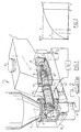
- the dosing device 1 shown in fig. 1 comprises a container 2 for additive 3, which can be introduced into container 2 using a filler cap 4.
- Additive 3 has to be added to a basic flow 5, which flows through a passage 6.
- a mixture of the basic flow 5 and the additive 3 added thereto is carried in the direction of arrow A to a further processing device 7, for instance an injection-moulding machine or an extruder.
- Passage 6 debouches into a neck part 8 with an inlet 9 for infeed of additive 3.
- a dosing mechanism 10 which comprises a dosing cylinder 11 for displacing additive 3 from container 2 to neck part 8.
- Dosing cylinder 11 is connected to a motor 12, for instance a stepping motor, which is driven by a control 13, which is connected in turn to a load cell 14 of the single point type which forms weighing means, and which comprises a compensation for shifting the centre of gravity of the container with the additive 3 therein.
- a signal representative of the weighed weight of container 2 with additive 3 is sent to control 13 by load cell 14, which can be an off-centre load cell.
- Control 13 processes the data coming from load cell 14 and drives the motor 12 on the basis hereof, whereby a higher or lower rotation speed of dosing cylinder 11 can be realized as desired.
- the motor thus forms a drive, controllable by the control, for the dosing mechanism formed by dosing cylinder 11.
- Load cell 14 forms the connection between neck part 8 and container 2. Dosing cylinder 11 protrudes loosely into the inlet 9 in neck part 8. Owing to the clearance between dosing cylinder 11 and inlet 9 of neck part 8 a reliable measurement can be obtained using load cell 14 in respect of the weight of container 2 and additive 3 therein. The clearance is however so small that no loss of material from the basic flow or additive can occur therealong.
- Container 2 has a form corresponding with the narrowed form of passage 6.
- the dosing cylinder 11 can be kept short, together with the distance between the container and the neck part.
- a change in the rotation speed of dosing cylinder 11 achieved with motor 12 thus has practically immediate result, and the configuration is compact and simple.
- Owing to the form of container 2 corresponding with the narrowing in passage 6 the centre of gravity of container 2 with the additive 3 therein shifts in obliquely downward direction as more additive 3 is introduced into the basic flow 5 with the dosing mechanism.
- Such a lateral displacement of the centre of gravity of container 2 with additive 3 results in a changing moment of force, which would influence the measurement with load cell 14.
- load cell 14 is provided with a compensation for such a shift.
- Such a load cell is for instance an off-centre load cell.
- Other load cells compensated for such shifts in centres of gravity, or other weighing means which are not sensitive to such shifts, can also be applied.
- On neck part 8 is for instance mounted a platform on which the container rests in freestanding manner with more conventional scales between the platform and container 2.
- the stated off-centre load cell is active within a predetermined range, which for instance forms a platform with known dimensions.
- a platform is for instance 400 mm x 400 mm.
- Such a platform can be physically present or, as in the case of fig. 1, formed by the bottom of container 2.
- the said off-centre load cell can weigh very accurately with a total error in the order of magnitude of 0.01% or even less. A very precise dosing is thus possible herewith.
- Dosing cylinder 11 comprises a helical worm 15 which is connected to a drive shaft 17, which is connected in turn to motor 12. Round the helical worm 15 is arranged a cylinder which is arranged fixedly on helical worm 15 and forms a unit therewith. Cylinder 16 thus co-rotates with helical worm 15 under the driving action of motor 12.
- the characteristic of dosing mechanism 10 displays a non-linearity in the relation between the discharge in mass per unit of time and the rotation speed of motor 12 imposed on dosing mechanism 10.
- Such a non-linear characteristic is plotted in fig. 2 for a specific type of additive 3.
- the characteristic shown in fig. 2 will have a different progression for a different additive 3 with other material properties.
- the non-linearity of this characteristic is related to the configuration of dosing cylinder 11, wherein cylinder 16 and helical worm 15 are fixed to each other.
- a desired discharge Y two possibilities of which are given in fig. 2, this can be fed into control 13 in order to drive the motor 12, for instance a stepping motor, on the basis thereof.
- an estimate X is made of a desired rotation speed.
- an error of estimation is however made, for instance due to variation in the material properties per shipment obtained from a producer.
- a higher discharge than Y is found to result.
- the control 13 On the basis of measurement results of the weight of container 2 with additive 3 therein, the control 13 thus provides adjustment of the rotation speed by driving motor 12, wherein the rotation speed is reduced to value X', wherein the desired value of discharge Y is realized.
- a similar situation occurs at the lower of the two values Y in fig. 2, wherein the rotation speed must however be increased from X to X' in order to obtain the desired value of discharge Y.
- the rotation speed X anticipated on the basis of prior knowledge, a discharge lower than the desired discharge Y was obtained.
- the load cell can also be arranged on the side of the neck part and the side of the container. It is further possible for more than one load cell to be applied, and for instance for the combined measuring result of the load cells to be applied.
- a damping can further be arranged in order to suppress or damp vibrations which could disturb the measurements.
- Such a damping can be designed as a bellows-shaped element under the load cell, in which for instance damping fluid, such as oil, water and so on, can then be arranged. It is herein not desirable for the damping to "carry" the load cell such that the measuring result is reduced, although in the application according to the invention the weight decrease is of particular importance, since speed of measurement is also an important factor in a desired operation of the dosing device.
- the damping can be arranged close to the neck part, but is expected to be more effective if it is placed close to the container under the load cell.
- Other variants and alternatives are also possible according to the invention as this is not only disclosed in the foregoing but is also defined in the appended claims.
Landscapes
- Chemical Kinetics & Catalysis (AREA)
- Chemical & Material Sciences (AREA)
- Mechanical Engineering (AREA)
- Engineering & Computer Science (AREA)
- General Physics & Mathematics (AREA)
- Physics & Mathematics (AREA)
- Manufacturing & Machinery (AREA)
- Processing And Handling Of Plastics And Other Materials For Molding In General (AREA)
- Vending Machines For Individual Products (AREA)
- Medicines Containing Plant Substances (AREA)
- Peptides Or Proteins (AREA)
- Electrical Discharge Machining, Electrochemical Machining, And Combined Machining (AREA)
- Paper (AREA)
- Accessories For Mixers (AREA)
Claims (7)
- Dosiervorrichtung (1), um einen Zusatzstoff (3) in einen Grundstrom zu mischen, umfassend:dadurch gekennzeichnet, dass die Dosieranlage (10) lose verbunden ist mit dem Einlass und zusammen mit dem Behältnis (2) von den Wägemitteln (14) getragen wird, um den Zusatzstoff in der Dosieranlage und in dem Behältnis zu wägen.einen Durchlass (6) für den Grundstrom (5);einen Einlass (9), um den Zusatzstoff in den Durchlass zuzuführen;ein Behältnis (2) für den Zusatzstoff, das über eine Dosieranlage (10) mit dem Einlass verbunden ist und einen steuerbaren Antrieb (12) zur Einleitung des Zusatzstoffes in den Einlass hat;Wägemittel (14), um das Gewicht des Zusatzstoffes zu bestimmen; undeine Steuerung (13) für den Antrieb, die mit den Wägemitteln zum Einstellen einer dosierten Zusatzstoffeinleitung in den Grundstrom verbunden ist,
- Vorrichtung gemäß Anspruch 1, wobei die Wägemittel (14) einen Ausgleich aufweisen um den Schwerpunkt des Behältnisses mit dem darin befindlichen Zusatzstoff zu verlagern.
- Vorrichtung gemäß Anspruch 1 oder 2, wobei die Wägemittel eine Wägezelle (14) umfassen.
- Vorrichtung gemäß Anspruch 2 oder 3, wobei die Wägezelle (14) eine außermittige Ausführung ist.
- Vorrichtung gemäß einem oder mehreren der vorstehenden Ansprüche, wobei der Einlass ein Kragenteil (8) umfasst, durch den der Durchlass (6) verläuft, und mit einer den Einlass (9) bildenden Öffnung, um dort einen Auslauf der Dosieranlage (10) lose aufzunehmen.
- Vorrichtung gemäß einem oder mehreren der vorstehenden Ansprüche, wobei die Dosieranlage (10) eine Förderschnecke in einer Trommel umfasst, die mit dem Antrieb verbunden ist und eine Dosiertrommel (11) bildet, wobei die Förderschnecke und die Trommel eine Einheit bilden.
- Vorrichtung gemäß Anspruch 6, wobei die Charakteristik der Einleitung ausgedrückt in Masse pro Zeiteinheit im Verhältnis zu der Umdrehungsgeschwindigkeit der Dosiertrommel (11) nicht-linear ist und die Steuerung (13) darauf eingestellt ist, mittels eines berichtigenden Algorithmus eine regulierbar dosierte Einleitung herbeizuführen, und zwar durch Regulierung der durch den Antrieb bewirkten Umdrehungsgeschwindigkeit der Dosiertrommel auf Grundlage von durch die Wägemittel vorgenommen Gewichtsbestimmungen.
Applications Claiming Priority (3)
| Application Number | Priority Date | Filing Date | Title |
|---|---|---|---|
| NL1015439 | 2000-06-14 | ||
| NL1015439A NL1015439C2 (nl) | 2000-06-14 | 2000-06-14 | Doseerinrichting. |
| PCT/NL2001/000440 WO2001096006A1 (en) | 2000-06-14 | 2001-06-11 | Dosing device |
Publications (2)
| Publication Number | Publication Date |
|---|---|
| EP1289639A1 EP1289639A1 (de) | 2003-03-12 |
| EP1289639B1 true EP1289639B1 (de) | 2004-09-29 |
Family
ID=19771540
Family Applications (1)
| Application Number | Title | Priority Date | Filing Date |
|---|---|---|---|
| EP01941306A Expired - Lifetime EP1289639B1 (de) | 2000-06-14 | 2001-06-11 | Dosiereinrichtung |
Country Status (8)
| Country | Link |
|---|---|
| US (1) | US6911607B2 (de) |
| EP (1) | EP1289639B1 (de) |
| AT (1) | ATE277683T1 (de) |
| AU (1) | AU2001274666A1 (de) |
| DE (1) | DE60106025T2 (de) |
| ES (1) | ES2223873T3 (de) |
| NL (1) | NL1015439C2 (de) |
| WO (1) | WO2001096006A1 (de) |
Families Citing this family (13)
| Publication number | Priority date | Publication date | Assignee | Title |
|---|---|---|---|---|
| US7075018B1 (en) * | 1998-12-09 | 2006-07-11 | Temafa Maschinenfabrik Gmbh | Mixing fibrous constituents |
| AT503853B1 (de) * | 2003-05-12 | 2008-01-15 | Steinwald Kurt | Vorrichtung zum dosieren pulverförmiger materialien |
| DE102005018917A1 (de) * | 2005-04-22 | 2006-11-02 | Schenck Process Gmbh | Schüttgutvorratsbehälter |
| US7323644B2 (en) * | 2005-10-04 | 2008-01-29 | Kabushiki Kaisha Matsui Seisakusho | Apparatus for measuring weight of powdered and granular materials |
| US7534970B2 (en) * | 2006-06-15 | 2009-05-19 | Schenck Accurate, Inc. | Counterbalanced dispensing system |
| CH703374B1 (de) * | 2010-06-24 | 2015-01-30 | Eversys Ag | Reinigungssystem für einen Getränkeautomaten, vorzugsweise eine Kaffeemaschine. |
| JP5926455B2 (ja) | 2012-06-04 | 2016-05-25 | ヘーエーアー プロセス エンジニアリング ナームロゼ フェンノートシャップ | フィーダ・ユニット、複数のフィーダ・ユニットを含むフィーダ・モジュール、及び1種又は2種以上の粉末の一定の質量流量を受容容器内へ放出する方法 |
| CN103852144B (zh) * | 2012-12-04 | 2016-04-13 | 梅特勒-托利多(常州)精密仪器有限公司 | 具有不间断称重功能的称重系统以及称重方法 |
| US9713893B2 (en) * | 2013-07-09 | 2017-07-25 | Wenger Manufacturing, Inc. | Method of preconditioning comestible materials using steam/water static mixer |
| US10012484B2 (en) | 2014-03-03 | 2018-07-03 | Adr International Limited | Method of improving the accuracy of rifle ammunition |
| CN104190297B (zh) * | 2014-08-15 | 2016-01-13 | 诸暨洁球环保科技有限公司 | 一种水处理加药装置 |
| CN110395595B (zh) * | 2019-08-01 | 2024-03-08 | 珠海格力智能装备有限公司 | 投料装置、尿素机和投料方法 |
| NL2029716B1 (nl) | 2021-11-11 | 2023-06-08 | Ferlin Trading B V | Verbeterde doseerinrichting voor een vormmachine voor het doseren van een eerste granulair materiaal aan het tweede granulair materiaal |
Family Cites Families (19)
| Publication number | Priority date | Publication date | Assignee | Title |
|---|---|---|---|---|
| CH543732A (de) * | 1971-09-15 | 1973-10-31 | Daester Fairtec Ag | Einrichtung zum Fördern, gravimetrischen Dosieren und Mischen von rieselfähigem Material mit anderen rieselfähigen oder flüssigen oder teigförmigen Materialien |
| US3804298A (en) * | 1972-07-25 | 1974-04-16 | R Ricciardi | Gravimetric feeder |
| US3927560A (en) * | 1973-12-20 | 1975-12-23 | Transducers Inc | Moment desensitization of load cells |
| US4088308A (en) * | 1976-11-15 | 1978-05-09 | Bethlehem Steel Corporation | System for controlling the flow of sinter to blast furnace |
| DE3330988A1 (de) * | 1983-08-27 | 1985-03-14 | Sartorius GmbH, 3400 Göttingen | Oberschalige analysenwaage |
| US4775949A (en) * | 1986-06-27 | 1988-10-04 | K-Tron International, Inc. | Weigh feeding system with stochastic control |
| CH671102A5 (de) * | 1986-12-16 | 1989-07-31 | Mettler Instrumente Ag | |
| DE3838906C1 (de) * | 1988-11-17 | 1990-05-23 | Sartorius Gmbh, 3400 Goettingen, De | |
| CH677534A5 (de) * | 1989-05-09 | 1991-05-31 | Mettler Toledo Ag | |
| DE3933471A1 (de) * | 1989-10-06 | 1991-04-18 | Schenck Ag Carl | Verfahren und vorrichtung zur verbesserung der dosiergenauigkeit einer geregelten differentialdosierwaage |
| CH679564A5 (en) * | 1989-10-31 | 1992-03-13 | Alexandra Bartsch | Biodegradable starch based moulded article prodn. - made by press processing a mixt. of starch (deriv.) and water or alcohol into a flowable gel which can be extruded or injection moulded |
| US5148943A (en) * | 1991-06-17 | 1992-09-22 | Hydreclaim Corporation | Method and apparatus for metering and blending different material ingredients |
| DE4305426A1 (de) * | 1993-02-22 | 1994-08-25 | Mettler Toledo Ag | Kraftmeßvorrichtung, insbesondere Waage |
| DE4312281A1 (de) * | 1993-04-15 | 1994-10-20 | Eirich Maschf Gustav | Verfahren und Vorrichtung zur gravimetrischen Dosierung und Vermischung mindestens zweier Komponenten |
| CH689901A5 (de) * | 1994-11-11 | 2000-01-14 | Mettler Toledo Gmbh | Ueberlastschutz für eine Präzisionswaage. |
| DE29714643U1 (de) * | 1997-08-16 | 1997-10-16 | Vollmar, Hartmut, 53639 Königswinter | Verwiegeeinrichtung für ein eine oder mehrere Komponenten enthaltendes Aufgabegut |
| ES2224328T3 (es) * | 1998-02-18 | 2005-03-01 | Mann + Hummel Protec Gmbh | Dispositivo para producto a granel sueltos. |
| AU2886899A (en) * | 1998-03-02 | 1999-09-20 | Matthew T. Morris | Candle with embedded glass |
| US6557391B2 (en) * | 2000-10-04 | 2003-05-06 | Mettler-Toledo Gmbh | Balance with a weighing-load carrier and a calibration device |
-
2000
- 2000-06-14 NL NL1015439A patent/NL1015439C2/nl not_active IP Right Cessation
-
2001
- 2001-06-11 AU AU2001274666A patent/AU2001274666A1/en not_active Abandoned
- 2001-06-11 EP EP01941306A patent/EP1289639B1/de not_active Expired - Lifetime
- 2001-06-11 ES ES01941306T patent/ES2223873T3/es not_active Expired - Lifetime
- 2001-06-11 AT AT01941306T patent/ATE277683T1/de not_active IP Right Cessation
- 2001-06-11 WO PCT/NL2001/000440 patent/WO2001096006A1/en not_active Ceased
- 2001-06-11 DE DE60106025T patent/DE60106025T2/de not_active Expired - Lifetime
- 2001-06-11 US US10/297,865 patent/US6911607B2/en not_active Expired - Lifetime
Also Published As
| Publication number | Publication date |
|---|---|
| EP1289639A1 (de) | 2003-03-12 |
| AU2001274666A1 (en) | 2001-12-24 |
| DE60106025T2 (de) | 2006-03-02 |
| ES2223873T3 (es) | 2005-03-01 |
| NL1015439C2 (nl) | 2001-12-17 |
| US20040011569A1 (en) | 2004-01-22 |
| DE60106025D1 (de) | 2004-11-04 |
| WO2001096006A1 (en) | 2001-12-20 |
| ATE277683T1 (de) | 2004-10-15 |
| US6911607B2 (en) | 2005-06-28 |
Similar Documents
| Publication | Publication Date | Title |
|---|---|---|
| EP1289639B1 (de) | Dosiereinrichtung | |
| US5148943A (en) | Method and apparatus for metering and blending different material ingredients | |
| KR910005301B1 (ko) | 연속 계량기에 의한 연속 벌크물질 생산량의 자동측정장치 | |
| RU2086931C1 (ru) | Способ регистрации потока продукции и устройство для его осуществления | |
| US20160221220A1 (en) | Volumetric mixer with monitoring system and control system | |
| US7534970B2 (en) | Counterbalanced dispensing system | |
| CN102216742B (zh) | 计量输送设备 | |
| JPH0369495A (ja) | 重量測定を伴う容器充填装置 | |
| JP2004520192A (ja) | 小分けにした材料を射出成形機に供給するためのシステム | |
| CN113196019A (zh) | 用于对用于倾注物料的配量设备在其储存容器的再填充期间进行重力调节的方法及用于实施该方法的配量设备 | |
| US4445627A (en) | Apparatus and method for adjustment of volumetric cavities for gravimetric metering of liquids | |
| US6109779A (en) | Continuous mixer, mixing installation having a continuous mixer and method of operating such a mixing installation | |
| US771764A (en) | Automatic feed-regulator. | |
| CN105839498B (zh) | 一种沥青冷再生粉料添加计量装置 | |
| GB2161282A (en) | Dispensing fluent material | |
| JPS63274441A (ja) | 粉体計量混合装置 | |
| US3117640A (en) | Apparatus for mixing concrete | |
| KR100532742B1 (ko) | 반도체의 화학물질 배합 장치 및 방법 | |
| US1656002A (en) | Method for proportioning total water in concrete | |
| JPH0413636Y2 (de) | ||
| SU1174768A1 (ru) | Устройство дл измерени расхода сыпучих материалов в потоке | |
| JP4640244B2 (ja) | 粉粒体供給装置 | |
| SU1679200A1 (ru) | Способ дозировани текучих пористых материалов | |
| NL1028205C2 (nl) | Bunkerinrichting alsmede werkwijze voor het aanpassen van een bunkerinrichting en werkwijze voor het regelen van de uitstroom van materiaal uit een bunker. | |
| SU865239A1 (ru) | Устройство дл дозировани кормов |
Legal Events
| Date | Code | Title | Description |
|---|---|---|---|
| PUAI | Public reference made under article 153(3) epc to a published international application that has entered the european phase |
Free format text: ORIGINAL CODE: 0009012 |
|
| 17P | Request for examination filed |
Effective date: 20021202 |
|
| AK | Designated contracting states |
Kind code of ref document: A1 Designated state(s): AT BE CH CY DE DK ES FI FR GB GR IE IT LI LU MC NL PT SE TR Designated state(s): AT BE CH CY DE DK ES FI FR GB GR IE IT LI LU MC NL PT SE TR |
|
| AX | Request for extension of the european patent |
Extension state: AL LT LV MK RO SI |
|
| 17Q | First examination report despatched |
Effective date: 20030530 |
|
| GRAP | Despatch of communication of intention to grant a patent |
Free format text: ORIGINAL CODE: EPIDOSNIGR1 |
|
| GRAS | Grant fee paid |
Free format text: ORIGINAL CODE: EPIDOSNIGR3 |
|
| GRAA | (expected) grant |
Free format text: ORIGINAL CODE: 0009210 |
|
| AK | Designated contracting states |
Kind code of ref document: B1 Designated state(s): AT BE CH CY DE DK ES FI FR GB GR IE IT LI LU MC NL PT SE TR |
|
| PG25 | Lapsed in a contracting state [announced via postgrant information from national office to epo] |
Ref country code: LI Free format text: LAPSE BECAUSE OF FAILURE TO SUBMIT A TRANSLATION OF THE DESCRIPTION OR TO PAY THE FEE WITHIN THE PRESCRIBED TIME-LIMIT Effective date: 20040929 Ref country code: BE Free format text: LAPSE BECAUSE OF FAILURE TO SUBMIT A TRANSLATION OF THE DESCRIPTION OR TO PAY THE FEE WITHIN THE PRESCRIBED TIME-LIMIT Effective date: 20040929 Ref country code: CH Free format text: LAPSE BECAUSE OF FAILURE TO SUBMIT A TRANSLATION OF THE DESCRIPTION OR TO PAY THE FEE WITHIN THE PRESCRIBED TIME-LIMIT Effective date: 20040929 Ref country code: AT Free format text: LAPSE BECAUSE OF FAILURE TO SUBMIT A TRANSLATION OF THE DESCRIPTION OR TO PAY THE FEE WITHIN THE PRESCRIBED TIME-LIMIT Effective date: 20040929 Ref country code: FI Free format text: LAPSE BECAUSE OF FAILURE TO SUBMIT A TRANSLATION OF THE DESCRIPTION OR TO PAY THE FEE WITHIN THE PRESCRIBED TIME-LIMIT Effective date: 20040929 |
|
| REG | Reference to a national code |
Ref country code: GB Ref legal event code: FG4D |
|
| REG | Reference to a national code |
Ref country code: CH Ref legal event code: EP |
|
| REG | Reference to a national code |
Ref country code: IE Ref legal event code: FG4D |
|
| REF | Corresponds to: |
Ref document number: 60106025 Country of ref document: DE Date of ref document: 20041104 Kind code of ref document: P |
|
| PG25 | Lapsed in a contracting state [announced via postgrant information from national office to epo] |
Ref country code: SE Free format text: LAPSE BECAUSE OF FAILURE TO SUBMIT A TRANSLATION OF THE DESCRIPTION OR TO PAY THE FEE WITHIN THE PRESCRIBED TIME-LIMIT Effective date: 20041229 Ref country code: GR Free format text: LAPSE BECAUSE OF FAILURE TO SUBMIT A TRANSLATION OF THE DESCRIPTION OR TO PAY THE FEE WITHIN THE PRESCRIBED TIME-LIMIT Effective date: 20041229 Ref country code: DK Free format text: LAPSE BECAUSE OF FAILURE TO SUBMIT A TRANSLATION OF THE DESCRIPTION OR TO PAY THE FEE WITHIN THE PRESCRIBED TIME-LIMIT Effective date: 20041229 |
|
| REG | Reference to a national code |
Ref country code: ES Ref legal event code: FG2A Ref document number: 2223873 Country of ref document: ES Kind code of ref document: T3 |
|
| LTIE | Lt: invalidation of european patent or patent extension |
Effective date: 20040929 |
|
| REG | Reference to a national code |
Ref country code: CH Ref legal event code: PL |
|
| PG25 | Lapsed in a contracting state [announced via postgrant information from national office to epo] |
Ref country code: CY Free format text: LAPSE BECAUSE OF FAILURE TO SUBMIT A TRANSLATION OF THE DESCRIPTION OR TO PAY THE FEE WITHIN THE PRESCRIBED TIME-LIMIT Effective date: 20050611 Ref country code: LU Free format text: LAPSE BECAUSE OF NON-PAYMENT OF DUE FEES Effective date: 20050611 |
|
| PG25 | Lapsed in a contracting state [announced via postgrant information from national office to epo] |
Ref country code: IE Free format text: LAPSE BECAUSE OF NON-PAYMENT OF DUE FEES Effective date: 20050613 |
|
| PG25 | Lapsed in a contracting state [announced via postgrant information from national office to epo] |
Ref country code: MC Free format text: LAPSE BECAUSE OF NON-PAYMENT OF DUE FEES Effective date: 20050630 |
|
| PLBE | No opposition filed within time limit |
Free format text: ORIGINAL CODE: 0009261 |
|
| STAA | Information on the status of an ep patent application or granted ep patent |
Free format text: STATUS: NO OPPOSITION FILED WITHIN TIME LIMIT |
|
| 26N | No opposition filed |
Effective date: 20050630 |
|
| ET | Fr: translation filed | ||
| REG | Reference to a national code |
Ref country code: IE Ref legal event code: MM4A |
|
| PG25 | Lapsed in a contracting state [announced via postgrant information from national office to epo] |
Ref country code: PT Free format text: LAPSE BECAUSE OF NON-PAYMENT OF DUE FEES Effective date: 20050228 |
|
| REG | Reference to a national code |
Ref country code: FR Ref legal event code: PLFP Year of fee payment: 16 |
|
| REG | Reference to a national code |
Ref country code: FR Ref legal event code: PLFP Year of fee payment: 17 |
|
| REG | Reference to a national code |
Ref country code: FR Ref legal event code: PLFP Year of fee payment: 18 |
|
| PGFP | Annual fee paid to national office [announced via postgrant information from national office to epo] |
Ref country code: TR Payment date: 20200619 Year of fee payment: 20 Ref country code: DE Payment date: 20200629 Year of fee payment: 20 Ref country code: FR Payment date: 20200625 Year of fee payment: 20 |
|
| PGFP | Annual fee paid to national office [announced via postgrant information from national office to epo] |
Ref country code: IT Payment date: 20200619 Year of fee payment: 20 Ref country code: GB Payment date: 20200629 Year of fee payment: 20 Ref country code: NL Payment date: 20200626 Year of fee payment: 20 |
|
| PGFP | Annual fee paid to national office [announced via postgrant information from national office to epo] |
Ref country code: ES Payment date: 20201001 Year of fee payment: 20 |
|
| REG | Reference to a national code |
Ref country code: DE Ref legal event code: R071 Ref document number: 60106025 Country of ref document: DE |
|
| REG | Reference to a national code |
Ref country code: NL Ref legal event code: MK Effective date: 20210610 |
|
| REG | Reference to a national code |
Ref country code: GB Ref legal event code: PE20 Expiry date: 20210610 |
|
| PG25 | Lapsed in a contracting state [announced via postgrant information from national office to epo] |
Ref country code: GB Free format text: LAPSE BECAUSE OF EXPIRATION OF PROTECTION Effective date: 20210610 |
|
| REG | Reference to a national code |
Ref country code: ES Ref legal event code: FD2A Effective date: 20211230 |
|
| PG25 | Lapsed in a contracting state [announced via postgrant information from national office to epo] |
Ref country code: ES Free format text: LAPSE BECAUSE OF EXPIRATION OF PROTECTION Effective date: 20210612 |