EP1289182A2 - Détection de signaux avec un récepteur dans un système dispersif en temps à antennes multiples - Google Patents
Détection de signaux avec un récepteur dans un système dispersif en temps à antennes multiples Download PDFInfo
- Publication number
- EP1289182A2 EP1289182A2 EP02252090A EP02252090A EP1289182A2 EP 1289182 A2 EP1289182 A2 EP 1289182A2 EP 02252090 A EP02252090 A EP 02252090A EP 02252090 A EP02252090 A EP 02252090A EP 1289182 A2 EP1289182 A2 EP 1289182A2
- Authority
- EP
- European Patent Office
- Prior art keywords
- joint
- equalizer
- signal
- fourier transform
- fast fourier
- Prior art date
- Legal status (The legal status is an assumption and is not a legal conclusion. Google has not performed a legal analysis and makes no representation as to the accuracy of the status listed.)
- Ceased
Links
Images


Classifications
-
- H—ELECTRICITY
- H04—ELECTRIC COMMUNICATION TECHNIQUE
- H04L—TRANSMISSION OF DIGITAL INFORMATION, e.g. TELEGRAPHIC COMMUNICATION
- H04L25/00—Baseband systems
- H04L25/02—Details ; arrangements for supplying electrical power along data transmission lines
- H04L25/03—Shaping networks in transmitter or receiver, e.g. adaptive shaping networks
- H04L25/03006—Arrangements for removing intersymbol interference
- H04L25/03012—Arrangements for removing intersymbol interference operating in the time domain
-
- H—ELECTRICITY
- H04—ELECTRIC COMMUNICATION TECHNIQUE
- H04B—TRANSMISSION
- H04B7/00—Radio transmission systems, i.e. using radiation field
- H04B7/02—Diversity systems; Multi-antenna system, i.e. transmission or reception using multiple antennas
- H04B7/04—Diversity systems; Multi-antenna system, i.e. transmission or reception using multiple antennas using two or more spaced independent antennas
- H04B7/08—Diversity systems; Multi-antenna system, i.e. transmission or reception using multiple antennas using two or more spaced independent antennas at the receiving station
- H04B7/0891—Space-time diversity
-
- H—ELECTRICITY
- H04—ELECTRIC COMMUNICATION TECHNIQUE
- H04L—TRANSMISSION OF DIGITAL INFORMATION, e.g. TELEGRAPHIC COMMUNICATION
- H04L1/00—Arrangements for detecting or preventing errors in the information received
- H04L1/02—Arrangements for detecting or preventing errors in the information received by diversity reception
- H04L1/06—Arrangements for detecting or preventing errors in the information received by diversity reception using space diversity
-
- H—ELECTRICITY
- H04—ELECTRIC COMMUNICATION TECHNIQUE
- H04B—TRANSMISSION
- H04B1/00—Details of transmission systems, not covered by a single one of groups H04B3/00 - H04B13/00; Details of transmission systems not characterised by the medium used for transmission
- H04B1/69—Spread spectrum techniques
- H04B1/707—Spread spectrum techniques using direct sequence modulation
-
- H—ELECTRICITY
- H04—ELECTRIC COMMUNICATION TECHNIQUE
- H04L—TRANSMISSION OF DIGITAL INFORMATION, e.g. TELEGRAPHIC COMMUNICATION
- H04L25/00—Baseband systems
- H04L25/02—Details ; arrangements for supplying electrical power along data transmission lines
- H04L25/03—Shaping networks in transmitter or receiver, e.g. adaptive shaping networks
- H04L25/03006—Arrangements for removing intersymbol interference
- H04L2025/03592—Adaptation methods
- H04L2025/03598—Algorithms
- H04L2025/03605—Block algorithms
-
- H—ELECTRICITY
- H04—ELECTRIC COMMUNICATION TECHNIQUE
- H04L—TRANSMISSION OF DIGITAL INFORMATION, e.g. TELEGRAPHIC COMMUNICATION
- H04L25/00—Baseband systems
- H04L25/02—Details ; arrangements for supplying electrical power along data transmission lines
- H04L25/03—Shaping networks in transmitter or receiver, e.g. adaptive shaping networks
- H04L25/03006—Arrangements for removing intersymbol interference
- H04L2025/03592—Adaptation methods
- H04L2025/03598—Algorithms
- H04L2025/03611—Iterative algorithms
- H04L2025/03617—Time recursive algorithms
-
- H—ELECTRICITY
- H04—ELECTRIC COMMUNICATION TECHNIQUE
- H04L—TRANSMISSION OF DIGITAL INFORMATION, e.g. TELEGRAPHIC COMMUNICATION
- H04L25/00—Baseband systems
- H04L25/02—Details ; arrangements for supplying electrical power along data transmission lines
- H04L25/0202—Channel estimation
- H04L25/024—Channel estimation channel estimation algorithms
- H04L25/0242—Channel estimation channel estimation algorithms using matrix methods
-
- H—ELECTRICITY
- H04—ELECTRIC COMMUNICATION TECHNIQUE
- H04L—TRANSMISSION OF DIGITAL INFORMATION, e.g. TELEGRAPHIC COMMUNICATION
- H04L25/00—Baseband systems
- H04L25/02—Details ; arrangements for supplying electrical power along data transmission lines
- H04L25/03—Shaping networks in transmitter or receiver, e.g. adaptive shaping networks
- H04L25/03006—Arrangements for removing intersymbol interference
- H04L25/03178—Arrangements involving sequence estimation techniques
- H04L25/03331—Arrangements for the joint estimation of multiple sequences
Definitions
- This invention relates to the art of wireless communications, and more particularly, to wireless communication systems using multiple antennas at the transmitter and multiple antennas at the receiver, so called multiple-input multiple-output (MIMO) systems.
- MIMO multiple-input multiple-output
- the bit error rate floor caused by time dispersion can be reduced by employing a joint equalizer for all of the respective transmit antenna - receive antenna pairings that are possible in the MIMO system.
- the resulting joint equalization compensates not only for the impact of the channel on the transmit antenna - receive antenna pairings but also for the interference of the other transmit antennas on any given receive antenna.
- the joint equalizer is a joint minimum mean square error (MMSE) equalizer, and in such an embodiment the joint equalization outperforms simply replicating the prior art minimum mean square error (MMSE) equalizer for each transmit antenna - receive antenna pairing.
- MMSE joint minimum mean square error
- the resulting chip streams are despread in the conventional manner and then the resulting dispread symbols may be further processed in the conventional manner.
- the despread symbols may be processed, in accordance with an aspect of the invention, so as to have their soft bits computed through the use of a posteriori probability (APP) metric.
- APP posteriori probability
- the despread symbols may be spatially whitened using a spatial whitening filter.
- the equalizer is iteratively computed so that a symbol from one transmit antenna is determined during each iteration. Initially the received samples are stored in a memory. After a symbol for an antenna is determined, the received samples for each of the remaining antennas are then recomputed by subtracting out the determined symbol from the samples as they existed prior to determining the symbol. Once all the symbols for all of the transmit antennas are determined for a symbol period are determined the operation begins anew with the samples corresponding to the next symbol period.
- any block diagrams herein represent conceptual views of illustrative circuitry embodying the principles of the invention.
- any flow charts, flow diagrams, state transition diagrams, pseudocode, and the like represent various processes which may be substantially represented in computer readable medium and so executed by a computer or processor, whether or not such computer or processor is explicitly shown.
- processors may be provided through the use of dedicated hardware as well as hardware capable of executing software in association with appropriate software.
- the functions may be provided by a single dedicated processor, by a single shared processor, or by a plurality of individual processors, some of which may be shared.
- processor or “controller” should not be construed to refer exclusively to hardware capable of executing software, and may implicitly include, without limitation, digital signal processor (DSP) hardware, network processor, application specific integrated circuit (ASIC), field programmable gate array (FPGA), read-only memory (ROM) for storing software, random access memory (RAM), and non-volatile storage. Other hardware, conventional and/or custom, may also be included.
- DSP digital signal processor
- ASIC application specific integrated circuit
- FPGA field programmable gate array
- ROM read-only memory
- RAM random access memory
- non-volatile storage Other hardware, conventional and/or custom, may also be included.
- any switches shown in the FIGS. are conceptual only. Their function may be carried out through the operation of program logic, through dedicated logic, through the interaction of program control and dedicated logic, or even manually, the particular technique being selectable by the implementor as more specifically understood from the context.
- any element expressed as a means for performing a specified function is intended to encompass any way of performing that function including, for example, a) a combination of circuit elements which performs that function or b) software in any form, including, therefore, firmware, microcode or the like, combined with appropriate circuitry for executing that software to perform the function.
- the invention as defined by such claims resides in the fact that the functionalities provided by the various recited means are combined and brought together in the manner which the claims call for. Applicant thus regards any means which can provide those functionalities as equivalent as those shown herein.
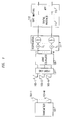
- FIG. 1 shows an exemplary embodiment of a multiple-input multiple-output (MIMO) wireless system in which the bit error rate floor caused by time dispersion is reduced by employing a joint minimum mean square error (MMSE) equalizer for all of the respective transmit antenna - receive antenna pairings that are possible in the MIMO system, in accordance with the principles of the invention. Shown in FIG.
- MIMO multiple-input multiple-output
- MMSE joint minimum mean square error
- ⁇ are a) transmitter 101; b) transmit antennas 103; including transmit antennas 103-1 through 103-M; c) receive antennas 105; including receive antennas 105-1 through 105-N; d) receiver front-end 107; e) joint equalizer 109; f) optional despreaders 111; g) soft bit mapper 112, which may include optional spatial whitening filter 113; and optional a posteriori probability (APP) metric processor 115.
- APP posteriori probability
- Transmitter 101 is a MIMO transmitter, e.g., one in which an original data stream is divided into substreams and each resulting substream is transmitted as a modulated radio signal via an individual one of transmit antennas 103.
- the transmitted signals pass to the receiver over a time dispersive channel such that signals from each transmit antenna 103 reach each of receive antennas 105.
- Receive antennas 105 convert the radio signals impinging upon them into electrical signals, which are supplied to receiver front-end 107.
- Receiver front-end 107 operates conventionally to produce a stream of binary numbers representing samples of the radio signals received at antennas 105.
- receiver front-end 107 performs radio frequency downconversion, filtering, sampling, and analog-to-digital conversion. The resulting samples are provided to joint equalizer 109.
- Joint equalizer 109 compensates for the effects of the transmit signals from each of antennas 103 having passed through the channel as well as the interference that results from transmitting via multiple antennas simultaneously.
- the output of joint equalizer 109 is M, i.e., the number of transmit antennas, streams of corrected symbols, or in the case of CDMA, streams of corrected chips which when properly combined form symbols. Operation of joint equalizer 109 will be described more fully hereinbelow. If CDMA is employed, the output of joint equalizer 109 is. supplied to optional despreaders 111, which produces symbols from the stream of chips supplied by joint equalizer 109.
- the symbols produced may then be further processed in the conventional manner for a MIMO system, e.g., soft bits may be developed by soft bit mapper 112 for use in a decoder, e.g., the well known "Turbo decoder".
- the symbols may be supplied within soft bit mapper 112 to optional spatial whitening filter 113, which makes the noise equal on each branch. Note that the whitening is performed only in the space domain. If whitening is performed in the time domain some temporal dispersion will be introduced into the signal.
- the symbols, or whitened symbols if optional spatial whitening filter 113 is employed, may further be supplied to optional a posteriori probability (APP) metric processor 115 within soft bit mapper 112, in accordance with an aspect of the invention.
- APP metric processor 115 performs a particular type of mapping from symbols to soft bits. Operation of APP metric processor 115 is described more fully hereinbelow.
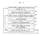
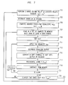
- FIG. 2 shows an exemplary process, in flow chart form, for the overall operation of system of FIG. 1.
- initial values of parameters M, N, L, P, E , and d must be determined. What each of these parameters represents is listed in Table 1.
- noise covariance R pp which contains samples of the autocorrelation of the chip pulse shape r(t) , when CDMA is employed, or the symbol pulse shape autocorrelation, when CDMA is not employed.
- the process of FIG. 2 is executed periodically, with a periodicity that preferably does not exceed the coherence time, T co , which is the time duration for which the channel properties are substantially constant.
- the process is entered in step 201, in which L*P discrete channel estimations h 0 to h LP-1 are developed.
- the channel estimate may be obtained using any conventional technique, e.g., by using correlators tuned to the pilot channel.
- Each of discrete channel estimations is taken with a time spacing of the chip duration divided by P, for CDMA, or symbol duration divided by P for TDMA.
- the background noise plus interference power ⁇ 2 / n and the power of the downlink from the base station to the terminal ⁇ 2 / x are determined in the conventional manner.
- the weights employed by joint equalizer 109 are determined, as will be described fully further hereinbelow.
- step 205 a set of P samples from each antenna is obtained.
- step 207 the determined weights of joint equalizer 109 are applied to the samples from each antenna by joint equalizer 109.
- the samples are then despread by despreader 111, if CDMA was employed, in optional step 209
- optional step 211 conventional soft mapping of the symbols to soft bits is performed, and the resulting soft bits are supplied as an output for use by a decoder.
- conditional branch point 213 tests to determine whether one coherence time has elapsed since the previous execution of step 201.
- test result in step 213 is NO, indicating that the channel is believed to still remain substantially the same as when it was last estimated, control passes to step 205, and the process continues as described above. If the test result in step 213 is YES, indicating that sufficient time has passed such that the channel may have changed enough so as not to be considered substantially the same as when it was last estimated, control passes back to step 201 and the process continues as described above.
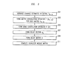
- FIG. 3 shows in more detail the process of step 203 by which the weights employed by joint equalizer 109. Note that the process requires the use of several matrices, and the dimensions of the various matrices are given in Table 2.
- step 301 the channel estimates h 0 to h LP-1 for each transmit and receive pair obtained in step 201 are arranged in a respective matrix h n.m as shown in equation 1.
- step 303 matrix convolution operator ⁇ ( h n,m ) is then formed for each respective matrix h n,m , as shown in equation 2.
- step 305 MIMO convolution operator ⁇ ( H ) is then formed from the various matrix convolution operators as shown in equation 3.
- delay vector e d is formed as shown in equation 4.
- Delay vector e d is a one dimensional vector with E+L-1 elements which are all zero except for the single value at the E+L-1-d location, which has a value of 1.
- a typical value for d, which is selectable by the implementor, is such that the location which has a value of 1 is at the center of the vector.
- the purpose of delay vector e d is to impose the overall equalizer delay d onto the equalizer.
- delay matrix A is computed from equation 5, in which I M is an identity matrix of size M ⁇ M.
- e d [0 ⁇ 1 0 0]
- A I M ⁇ e d
- equalizer weight matrix, W is computed in accordance with equation 6, in which X H means the Hermitian transpose of X, which is the complex conjugate transpose of the vector or matrix X.
- W A ⁇ (H) H ( ⁇ (H) H ⁇ (H+ ⁇ )R pp ) -1
- step 205 execution of step 205 is such that the P samples r of antenna n are initially arranged as a vector c shown in equation 7, where k is the current received chip time index if CDMA is employed, or the symbol time index if CDMA is not employed. E consecutive in time vectors c for antenna n are then arranged as shown in equation 8, and the E consecutive in time vectors c for all of the N antennas are further arranged as shown in equation 9, forming a vector of received samples at time k .
- y ( k ) is a resulting vector of size M ⁇ 1 which contains the equalized chips if CDMA is employed, or symbols if • CDMA is not employed.
- y( k ) Wr( k )
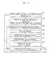
- FIG. 4 shows another exemplary process, in flow chart form, for the overall operation of system of FIG. 1.
- the version of the process shown in FIG. 4 is similar to that shown in FIG. 2, but it is for embodiments of the invention that include optional spatial whitening filter 113 (FIG. 1) and optional a posteriori probability (APP) metric processor 115.
- APP a posteriori probability
- the process of FIG. 4 is executed periodically, with a periodicity that preferably does not exceed the coherence time, T co , which is the time duration for which the channel properties are substantially constant.
- the process is entered in step 401, in which L*P discrete channel estimations h 0 to h LP-1 are developed.
- the background noise plus interference power ⁇ 2 / n and the power of the downlink from the base station to the terminal ⁇ 2 / x are determined in the conventional manner.
- the weights W employed by joint equalizer 109 are determined, as described hereinabove.
- the effective channel matrix H eff and, optionally, spatial whitening filter Q are determined, in accordance with an aspect of the invention.
- H eff is determined as shown in equation 11, and Q is determined as shown in equation 12.
- step 405 a set of P samples from each antenna is obtained. Thereafter, in step 407, the determined weights of joint equalizer 109 are applied to the samples from each antenna by joint equalizer 109. The samples are then despread by despreader 111, if CDMA was employed, in optional step 409. In step 411, whitening filter Q is applied to the despread, equalizer outputs of step 409. In step 413, APP softbits are computed, in accordance with an aspect of the invention, using equations 13 and 14. The softbits are the output of the process of FIG. 4, and they may be made available to a decoder, e.g., a turbo decoder.
- a decoder e.g., a turbo decoder.
- conditional branch point 415 tests to determine whether one coherence time has elapsed since the previous execution of step 401. If the test result in step 415 is NO, indicating that the channel is believed to still remain substantially the same as when it was last estimated, control passes to step 405, and the process continues as described above. If the test result in step 415 is YES, indicating that sufficient time has passed such that the channel may have changed enough so as not to be considered substantially the same as when it was last estimated, control passes back to step 401 and the process continues as described above.
- FIG. 5 shows another exemplary embodiment of a multiple-input multiple-output (MIMO) wireless system in which the bit error rate floor caused by time dispersion is reduced by employing a joint minimum mean square error (MMSE) equalizer for all of the respective transmit antenna - receive antenna pairings that are possible in the MIMO system, in accordance with the principles of the invention.
- MIMO multiple-input multiple-output
- MMSE joint minimum mean square error
- 5 are a) transmitter 501; b) transmit antennas 503; including transmit antennas 503-1 through 503-M; c) receive antennas 505; including receive antennas 505-1 through 505-N; d) receiver front-end processor 507; e) buffer-subtractor 521; f) joint equalizer 523; g) optional despreader 525; h) soft bit mapper 527; i) space-time regenerator 529; j) order controller 531 and k) switch 533.
- Transmitter 501 is a MIMO transmitter, e.g., one in which an original data stream is divided into substreams and each resulting substream is transmitted as a modulated radio signal via an individual one of transmit antennas 503.
- the transmitted signals pass to the receiver over a time dispersive channel such that signals from each transmit antenna 503 reach each of receive antennas 505.
- Receive antennas 505 convert the radio signals impinging upon them into electrical signals, which are supplied to receiver front-end processor 507.
- Receiver front-end processor 507 operates conventionally to produce a stream of binary numbers representing samples of the radio signals received at antennas 505.
- receiver front-end processor 507 performs radio frequency downconversion, filtering, sampling, and analog-to-digital conversion. The resulting samples are provided to buffer-substractor 521.
- Buffer-subtractor 521 is shown in more detail in FIG. 6.
- Buffer subtractor 521 includes buffer 601, memory 603, and subtractor 605.
- Buffer 601 stores a time consecutive set of samples from each of antennas 505 as those samples become available from front-end processor 507.
- Buffer 601 supplies the samples it receives from front-end processor 507 to memory 603 when an entire set is stored, i.e., the contents of buffer 601 are quickly dumped to memory 603.
- Subtractor 605 is cable of forming the difference between a specified location in memory 603 and a second input to buffer-subtractor 521. The resulting difference is stored in the specified location in memory 603.
- Joint equalizer 523 performs M passes through memory 603 with a different equalizer weight w m in each pass. Each weight is chosen to emphasize transmit antenna m and to suppress transmit antennas m +1 through M.
- joint equalizer 523 is supplied to conventional soft bit mapper 527, via optional conventional despreader 525 if CDMA is employed.
- soft bits developed by soft bit mapper 527 are then supplied as an output, such as may be used by a decoder, e.g., the well known "Turbo decoder".
- Space-time regenerator 529 forms a set of time consecutive samples for each receive antenna assuming the soft symbol is correct. In other words, assuming a particular soft symbol had been the actual symbol transmitted by a particular transmit antenna, space-time regenerator 529 creates the corresponding effect that such a symbol would have caused on each of receive antennas 505 given the channel characteristics. Operation of space-time regenerator 529 will be explained more fully hereinbelow.
- Order controller 531 determines, based on channel estimates, the signal from which transmit antenna will be processed at any particular time, as will be explained more fully hereinbelow.
- FIG. 7 shows an exemplary process, in flow chart form, for the overall operation of system of FIG. 5 in which switch 533 is connected between despreader 525 and space-time regenerator 529.
- initial values of parameters M, N, L, P, E , and d must be determined. What each of these parameters represents is listed in Table 1. Additionally, prior to performing the process of FIG. 7 it is necessary to determine R pp , which is samples of the autocorrelation of the chip pulse shape r(t) , when CDMA is employed, or the symbol pulse shape autocorrelation, when CDMA is not employed.
- the process of FIG. 7 is executed periodically, with a periodicity that preferably does not exceed the coherence time, T co .
- the process is entered in step 701, in which L*P discrete channel estimations h 0 to h LP-1 are developed.
- the channel estimate may be obtained using any conventional technique, e.g., by using correlators tuned to the pilot channel.
- Each discrete channel estimation is taken with a time spacing of the chip duration divided by P, for CDMA, or symbol duration divided by P for TDMA.
- the background noise plus interference power ⁇ 2 / n and the power of the downlink from the base station to the terminal ⁇ 2 / x are determined in the conventional manner.
- order controller 531 determines, according to equations 15 and 16, the order in which the signals from the various transmit antennas will be processed, with the signal from a respective transmit antenna being processed for each execution of joint equalizer 523.
- Sort is a function that rearranges the elements of vector P so that they run from largest to smallest and order is a list of all the antenna transmit antenna numbers as they should be processed by joint equalizer 523. It is preferable to process the so-called “strong" signals first.
- the particular characteristic, or set of characteristics, which are used to define the "strength" of a signal is at the discretion of the implementer. In the particular embodiment shown herein, estimated signal powers are employed as the strength.
- step 705 the equalizer weights for the particular antenna currently being processed, m , as specified by the order, is determined according to equations 17 and 18, in which delay vector a m is the m th row of delay matrix A which was described hereinabove.
- w m a m ⁇ (H m ) H ⁇ (H m ) H ⁇ (H m )+ ⁇ 2 n ⁇ 2 x R pp -1
- order is vector which contains a listing of the M antenna numbers in the order in which they will be processed. Order may be the result of the well known function sort of MatLab®. Doing so accounts for the fact that signals from transmit antennas 1 through m-1 have already been subtracted from the signal remaining to be processed for this set of samples.
- step 707 a set of samples that span at least the duration of a data symbol is obtained from each receive antenna.
- counter variable m is initialized to 1.
- the samples are then despread by despreader 525, if CDMA was employed, in optional step 713.
- step 715 conventional soft mapping of the symbols to soft bits is performed, and the resulting soft bits are supplied as an output for use by a decoder.
- step 717 samples are produced by space-time regenerator 529 according to equations 20 and 21.
- step 719 the output of space-time regenerator 529 is subtracted from the contents of memory 603 (FIG. 6), as shown by equation 22.
- r( k ) r( k ) - y m ( k )
- conditional branch point 721 tests to determine if m is equal to M . If the test result in step 721 is NO, indicating that not all of the transmit antennas have yet had their signal contribution processed, m is incremented in step 723. Thereafter, control passes back to step 711 and the process continues as described above. If the test result in step 712 is YES, indicating that all of the transmit antennas have had their signal contribution processed, control passes to conditional branch point 725, which tests to determine whether one coherence time has elapsed since the previous execution of step 701. If the test result in step 725 is NO, indicating that the channel is believed to still remain substantially the same as when it was last estimated, control passes to step 707, and the process continues as described above. If the test result in step 725 is YES, indicating that sufficient time has passed such that the channel may have changed enough so as not to be considered substantially the same as when it was last estimated, control passes back to step 701 and the process continues as described above.
- switch 533 is connected to the output of an error correction decoder which is either directly or indirectly connected to soft bit mapping 527. Doing so may improve performance.
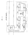
- FIG. 8 shows a particular embodiment of joint equalizer 109, in which the equalization is performed in the discrete frequency domain, in accordance with an aspect of the invention.
- Shown in FIG. 8 making up joint equalizer 109 are a) fast Fourier transform (FFT) processors 801, including FFT processors 801-1 through 801-N, where N is the number of receive antennas; b) channel estimators 803, including channel estimators 803-1 through 803-N; c) fast Fourier transform (FFT) processors 805, including FFT processors 805-1 through 805-N*M, where M is the number of transmit antennas; d) MMSE detection per frequency bin processor 807; and e) inverse fast Fourier transform (IFFT) processors 809, including IFFT processors 809-1 through 809-M.
- FFT fast Fourier transform
- Each of FFT processors 801 receives from front-end 107 a signal of time domain digital samples corresponding to a respective one of receive antennas 105-N and performs the FFT algorithm on a set of consecutive samples to convert the time domain samples to samples in the discrete frequency domain, r n ( ⁇ ), where ⁇ is a particular discrete frequency.
- the number of samples F is at the discretion of the implementer based on a tradeoff between the performance and complexity of FFT processors 801. Typically the number of samples is a power of 2, e.g., 128, although the more samples the more accurate the equalization process will be.
- the resulting discrete frequency samples for each receive antenna are supplied to MMSE detection per frequency bin processor 807.
- Each of channel estimators 803 also receives from front-end 107 a signal of time domain digital samples corresponding to a respective one of receive antennas 105-N and performs a channel estimate for the channel between its respective receive antenna and each of the M transmit antennas, thereby producing M channel estimates.
- Each channel estimate is a series of complex numbers that defines the impulse response of the channel.
- FFT Fast Fourier transform
- processors 805 each converts a respective channel estimate into the discrete frequency domain representation thereof, and supplies the resulting discrete frequency domain representation of the channel estimates h n,m ( ⁇ ) to MMSE detection per frequency bin processor 807.
- Each of the resulting M components of resulting vector z ( ⁇ ) are then inverse frequency transformed from the discrete frequency domain into the time domain by inverse fast Fourier transform (IFFT) processors 809.
- IFFT inverse fast Fourier transform
- the time domain equalized outputs are then supplied as the output of joint equalizer 109.
- FIG. 9 shows a particular embodiment of joint equalizer 109 in which the equalization is calculated in the discrete frequency domain and applied in the time domain, in accordance with an aspect of the invention.
- Shown in FIG. 9 making up joint equalizer 109 are a) matrix finite impulse response (FIR) filter 901; b) channel estimators 903, including channel estimators 903-1 through 903-N; c) fast Fourier transform (FFT) processors 905, including FFT processors 905-1 through 905-N*M, where M is the number of transmit antennas; d) MMSE tap weight calculator 907; and e) inverse fast Fourier transform (IFFT) processors 909, including IFFT processors 909-1 through 909- N*M
- Matrix finite impulse response (FIR) filter 901 continuously receives from front-end 107 a signal of time domain digital samples corresponding to a respective one of receive antennas 105-N.
- the number of taps of matrix FIR filter 901 is at the discretion of the implementer based on a tradeoff between performance and complexity. Typically the number of samples is a power of 2, e.g., 128.
- Each of channel estimators 903 also receives from front-end 107 a signal of time domain digital samples corresponding to a respective one of receive antennas 105-N and performs a channel estimate for the channel between its respective receive antenna and each of the M transmit antennas, thereby producing M channel estimates.
- Each channel estimate is a series of complex numbers that defines the impulse response of the channel.
- FFT Fast Fourier transform
- processors 905 each converts a respective channel estimate into the discrete frequency domain, and supplies the resulting discrete frequency domain representation of the channel estimates h n,m ( ⁇ ) to MMSE tap weight calculator 907.
- the number of samples employed by FFT processors 905 for each conversion should be the same as the number of taps in matrix FIR filter 901.
- Each of the resulting M components of resulting vector S ( ⁇ ) are grouped by frequency into frequency vectors, and are then the frequency vectors are inverse frequency transformed from the discrete frequency domain to become filter weights in the time domain by inverse fast Fourier transform (IFFT) processors 909.
- IFFT inverse fast Fourier transform
- weights are then supplied to matrix FIR filter 901 which utilizes them to perform equalization in the time domain on the signals received from front-end 107 as shown by equation 28, where y ( k ) is the vector output at time k , y having M components ⁇ one for each transmit antenna ⁇ , S j is the MxN filter matrix for delay j, which is the inverse Fourier transform of S ( ⁇ ), r ( k ) is the vector input signal which is received by matrix FIR filter 901 as defined in equation (9), and F is the number of samples taken for each FFT.
- equalizer algorithms which approximate the operation and performance of MMSE, such as least mean square (LMS), recursive least squares (RLS), or minimum intersymbol interference (ISI) subject to an anchor condition, can be employed in a joint manner, e.g., in a space manner, in the implementation of joint equalizer 109.
- LMS least mean square
- RLS recursive least squares
- ISI minimum intersymbol interference
- the techniques of the instant invention may be employed in systems in which the various transmit antennas are transmitting at different data rates, e.g., using different encoding rates and/or transmit constellations, such as quaternary phase-shift keying (QPSK) or 16-ary quadrature amplitude modulation (16-QAM).
- QPSK quaternary phase-shift keying
- 16-QAM 16-ary quadrature amplitude modulation
Applications Claiming Priority (2)
| Application Number | Priority Date | Filing Date | Title |
|---|---|---|---|
| US09/938,453 US7359466B2 (en) | 2001-08-24 | 2001-08-24 | Signal detection by a receiver in a multiple antenna time-dispersive system |
| US938453 | 2004-09-10 |
Publications (2)
| Publication Number | Publication Date |
|---|---|
| EP1289182A2 true EP1289182A2 (fr) | 2003-03-05 |
| EP1289182A3 EP1289182A3 (fr) | 2003-04-16 |
Family
ID=25471471
Family Applications (1)
| Application Number | Title | Priority Date | Filing Date |
|---|---|---|---|
| EP02252090A Ceased EP1289182A3 (fr) | 2001-08-24 | 2002-03-22 | Détection de signaux avec un récepteur dans un système dispersif en temps à antennes multiples |
Country Status (3)
| Country | Link |
|---|---|
| US (1) | US7359466B2 (fr) |
| EP (1) | EP1289182A3 (fr) |
| JP (1) | JP2003110474A (fr) |
Cited By (11)
| Publication number | Priority date | Publication date | Assignee | Title |
|---|---|---|---|---|
| GB2400000A (en) * | 2003-03-24 | 2004-09-29 | Univ Bristol | Iterative frequency domain equalizer for a MIMO system receiver |
| WO2005081482A1 (fr) * | 2004-02-13 | 2005-09-01 | Nokia Corporation | Structure d'egalisateur au niveau de la puce ou au niveau du symbole pour plusieurs configurations d'antennes d'emission et de reception |
| EP1587264A2 (fr) | 2004-04-16 | 2005-10-19 | NTT DoCoMo, Inc. | Estimation de canal pour la transmission à entrées et sorties multiples |
| EP1610513A1 (fr) * | 2004-06-22 | 2005-12-28 | Lucent Technologies Inc. | Egalisation adaptative d'un signal AMCR dans le domain fréquentiel |
| WO2006029789A1 (fr) * | 2004-09-17 | 2006-03-23 | Telefonaktiebolaget L M Ericsson (Publ) | Procede et appareil permettant de supprimer les parasites dans un signal de telecommunication |
| US7321646B2 (en) | 2003-11-18 | 2008-01-22 | Telefonaktiebolaget Lm Ericsson (Publ) | Methods and apparatus for pre-filtering a signal to increase signal-to-noise ratio and decorrelate noise |
| EP1903729A2 (fr) * | 2006-09-21 | 2008-03-26 | Broadcom Corporation | Égalisateur de domaine de fréquence avec annulation d'interférences dominantes pour radio à antenne double |
| US9071822B2 (en) | 2005-09-27 | 2015-06-30 | Qualcomm Incorporated | Methods and device for data alignment with time domain boundary |
| US9131164B2 (en) | 2006-04-04 | 2015-09-08 | Qualcomm Incorporated | Preprocessor method and apparatus |
| US9197912B2 (en) | 2005-03-10 | 2015-11-24 | Qualcomm Incorporated | Content classification for multimedia processing |
| CN109117698A (zh) * | 2017-12-27 | 2019-01-01 | 南京世海声学科技有限公司 | 一种基于最小均方误差准则的噪声背景估计方法 |
Families Citing this family (76)
| Publication number | Priority date | Publication date | Assignee | Title |
|---|---|---|---|---|
| US7769078B2 (en) * | 2000-12-22 | 2010-08-03 | Telefonaktiebolaget Lm Ericsson (Publ) | Apparatus, methods and computer program products for delay selection in a spread-spectrum receiver |
| US9236902B2 (en) * | 2001-08-28 | 2016-01-12 | Texas Instruments Incorporated | Combined equalizer and spread spectrum interference canceller method and implementation for the downlink of CDMA systems |
| JP3814182B2 (ja) * | 2001-10-17 | 2006-08-23 | 国立大学法人 北海道大学 | 無線装置およびアダプティブアレイ処理方法 |
| US20030161258A1 (en) * | 2002-02-22 | 2003-08-28 | Jianzhong Zhang | Apparatus, and associated method, for a multiple-input, multiple-output communications system |
| CN100340068C (zh) | 2002-04-22 | 2007-09-26 | Ipr许可公司 | 多输入多输出无线通信方法及具有无线前端部件的收发机 |
| US6757321B2 (en) | 2002-05-22 | 2004-06-29 | Interdigital Technology Corporation | Segment-wise channel equalization based data estimation |
| US7212566B2 (en) * | 2002-06-26 | 2007-05-01 | Nokia Corporation | Apparatus, and associated method, for performing joint equalization in a multiple-input, multiple-output communication system |
| US7167507B2 (en) * | 2002-07-01 | 2007-01-23 | Lucent Technologies Inc. | Equalizer and method for performing equalization in a wireless communications system |
| US7346103B2 (en) | 2003-03-03 | 2008-03-18 | Interdigital Technology Corporation | Multi user detection using equalization and successive interference cancellation |
| KR101021569B1 (ko) * | 2003-03-03 | 2011-03-16 | 인터디지탈 테크날러지 코포레이션 | 복잡도가 감소된 슬라이딩 윈도우 기반의 등화기 |
| US7042967B2 (en) * | 2003-03-03 | 2006-05-09 | Interdigital Technology Corporation | Reduced complexity sliding window based equalizer |
| JP2005057497A (ja) | 2003-08-04 | 2005-03-03 | Science Univ Of Tokyo | 無線伝送制御方法並びに無線受信装置及び無線送信装置 |
| WO2005020522A1 (fr) * | 2003-08-26 | 2005-03-03 | Koninklijke Philips Electronics, N.V. | Dispositif sans fil a ajustement dynamique du seuil de fragmentation |
| US7428260B2 (en) * | 2003-10-30 | 2008-09-23 | Marvell World Trade Ltd. | Unified MMSE equalization and multi-user detection approach for use in a CDMA system |
| US7437135B2 (en) * | 2003-10-30 | 2008-10-14 | Interdigital Technology Corporation | Joint channel equalizer interference canceller advanced receiver |
| US7616698B2 (en) | 2003-11-04 | 2009-11-10 | Atheros Communications, Inc. | Multiple-input multiple output system and method |
| FI20031609A0 (fi) * | 2003-11-06 | 2003-11-06 | Nokia Corp | Viestintämenetelmä, vastaanotin ja tukiasema |
| KR100703263B1 (ko) | 2003-12-02 | 2007-04-03 | 삼성전자주식회사 | 다중 안테나를 사용하는 이동통신 시스템에서 간섭신호제거 장치 및 방법 |
| US8204149B2 (en) * | 2003-12-17 | 2012-06-19 | Qualcomm Incorporated | Spatial spreading in a multi-antenna communication system |
| KR100580843B1 (ko) * | 2003-12-22 | 2006-05-16 | 한국전자통신연구원 | V―blast에서 채널전달함수행렬 처리장치 및 그의처리방법 |
| US7336746B2 (en) * | 2004-12-09 | 2008-02-26 | Qualcomm Incorporated | Data transmission with spatial spreading in a MIMO communication system |
| KR100605861B1 (ko) * | 2004-02-02 | 2006-08-01 | 삼성전자주식회사 | 다중 입력 다중 출력 방식을 사용하는 통신 시스템의 신호수신 장치 및 방법 |
| US20050180312A1 (en) * | 2004-02-18 | 2005-08-18 | Walton J. R. | Transmit diversity and spatial spreading for an OFDM-based multi-antenna communication system |
| US8169889B2 (en) | 2004-02-18 | 2012-05-01 | Qualcomm Incorporated | Transmit diversity and spatial spreading for an OFDM-based multi-antenna communication system |
| US20070280336A1 (en) * | 2004-02-27 | 2007-12-06 | Nokia Corporation | Constrained Optimization Based Mimo Lmmse-Sic Receiver for Cdma Downlink |
| US20050238111A1 (en) * | 2004-04-09 | 2005-10-27 | Wallace Mark S | Spatial processing with steering matrices for pseudo-random transmit steering in a multi-antenna communication system |
| US8285226B2 (en) * | 2004-05-07 | 2012-10-09 | Qualcomm Incorporated | Steering diversity for an OFDM-based multi-antenna communication system |
| US8923785B2 (en) | 2004-05-07 | 2014-12-30 | Qualcomm Incorporated | Continuous beamforming for a MIMO-OFDM system |
| US7110463B2 (en) | 2004-06-30 | 2006-09-19 | Qualcomm, Incorporated | Efficient computation of spatial filter matrices for steering transmit diversity in a MIMO communication system |
| US7978649B2 (en) | 2004-07-15 | 2011-07-12 | Qualcomm, Incorporated | Unified MIMO transmission and reception |
| CN1993953B (zh) * | 2004-08-05 | 2011-01-26 | 松下电器产业株式会社 | 无线发送装置和无线发送方法 |
| US7978778B2 (en) | 2004-09-03 | 2011-07-12 | Qualcomm, Incorporated | Receiver structures for spatial spreading with space-time or space-frequency transmit diversity |
| US7433434B2 (en) * | 2004-10-01 | 2008-10-07 | General Dynamics C4 Systems, Inc. | Communication channel tracking apparatus |
| US7539262B2 (en) * | 2004-12-14 | 2009-05-26 | Interdigital Technology Corporation | Method and apparatus for performing chip level equalization using joint processing |
| US8780957B2 (en) * | 2005-01-14 | 2014-07-15 | Qualcomm Incorporated | Optimal weights for MMSE space-time equalizer of multicode CDMA system |
| WO2006075732A1 (fr) * | 2005-01-17 | 2006-07-20 | Sharp Kabushiki Kaisha | Appareil de communication sans fil |
| US7570689B2 (en) * | 2005-02-14 | 2009-08-04 | Interdigital Technology Corporation | Advanced receiver with sliding window block linear equalizer |
| JP2006246176A (ja) * | 2005-03-04 | 2006-09-14 | Nec Corp | Mimo受信装置、受信方法および無線通信システム |
| JP2006311083A (ja) * | 2005-04-27 | 2006-11-09 | Nec Corp | Cdma受信方法および装置ならびに無線通信システム |
| US20060251421A1 (en) * | 2005-05-09 | 2006-11-09 | Ben Gurion University Of The Negev, Research And Development Authority | Improved free space optical bus |
| CA2516000A1 (fr) * | 2005-08-15 | 2007-02-15 | Research In Motion Limited | Filtres optimaux combines espace-temps (jstof) comportant au moins une antenne virtuelle, au moins une voie et une estimation de la ponderation du filtrage combine et de la reponse impulsionnelle de voie |
| JP4666150B2 (ja) * | 2005-05-31 | 2011-04-06 | 日本電気株式会社 | Mimo受信装置、受信方法、および無線通信システム |
| US7548589B2 (en) * | 2005-06-13 | 2009-06-16 | Qualcomm Incorporated | Method and apparatus for generating weights for transmit diversity in wireless communication |
| US20070133814A1 (en) * | 2005-08-15 | 2007-06-14 | Research In Motion Limited | Joint Space-Time Optimum Filter (JSTOF) Using Cholesky and Eigenvalue Decompositions |
| US20070042741A1 (en) * | 2005-08-15 | 2007-02-22 | Research In Motion Limited | Wireless Communications Device Including a Joint Space-Time Optimum Filters (JSTOF) Using QR and Eigenvalue Decompositions |
| US20070053416A1 (en) * | 2005-09-08 | 2007-03-08 | Yuan Li | Methods and apparatus to perform closed-loop transmit diversity with frequency-domain equalizers |
| US20070053417A1 (en) * | 2005-09-08 | 2007-03-08 | Toshio Nagata | Methods and apparatus to perform fractional-spaced channel estimation for frequency-domain equalizers |
| US8345733B2 (en) * | 2005-09-13 | 2013-01-01 | At&T Intellectual Property I, Lp | Method and apparatus for equalizing signals |
| US7852951B2 (en) * | 2005-09-30 | 2010-12-14 | Intel Corporation | Multicarrier receiver for multiple-input multiple-output wireless communication systems and method |
| US8654848B2 (en) | 2005-10-17 | 2014-02-18 | Qualcomm Incorporated | Method and apparatus for shot detection in video streaming |
| US8948260B2 (en) * | 2005-10-17 | 2015-02-03 | Qualcomm Incorporated | Adaptive GOP structure in video streaming |
| US20070171280A1 (en) * | 2005-10-24 | 2007-07-26 | Qualcomm Incorporated | Inverse telecine algorithm based on state machine |
| KR101019397B1 (ko) * | 2005-11-21 | 2011-03-07 | 퀄컴 인코포레이티드 | 멀티코드 cdma 시스템의 mmse 공간-시간 등화기에대한 최적의 가중치 |
| KR20070061215A (ko) * | 2005-12-08 | 2007-06-13 | 한국전자통신연구원 | 다중 반송파를 이용한 광대역 무선 채널 측정 장치의송수신 장치 |
| US20070230638A1 (en) * | 2006-03-30 | 2007-10-04 | Meir Griniasty | Method and apparatus to efficiently configure multi-antenna equalizers |
| CN100444543C (zh) * | 2006-03-31 | 2008-12-17 | 东南大学 | 用于多天线无线通信系统空域滤波检测方法 |
| CN100499611C (zh) * | 2006-03-31 | 2009-06-10 | 东南大学 | 无线通信系统空域最大后验概率检测方法 |
| US8543070B2 (en) | 2006-04-24 | 2013-09-24 | Qualcomm Incorporated | Reduced complexity beam-steered MIMO OFDM system |
| US8290089B2 (en) * | 2006-05-22 | 2012-10-16 | Qualcomm Incorporated | Derivation and feedback of transmit steering matrix |
| US8508369B2 (en) * | 2006-09-01 | 2013-08-13 | Intermec Ip Corp. | RFID tag system with block coding, such as space-time block coding |
| US8754749B2 (en) | 2006-09-01 | 2014-06-17 | Intermec Ip Corp. | RFID tags with CDMA communication capabilities |
| WO2008027623A2 (fr) * | 2006-09-01 | 2008-03-06 | Intermec Ip Corp. | Etiquettes rfid ayant des capacités de communication orthogonale et systèmes associés |
| EP2095587B1 (fr) * | 2006-11-06 | 2019-12-25 | QUALCOMM Incorporated | Détection mimo avec suppression d'interférences sur les composantes de signal temporelles |
| KR100949987B1 (ko) * | 2007-01-04 | 2010-03-26 | 삼성전자주식회사 | 무선통신시스템에서 수신 장치 및 방법 |
| KR101059969B1 (ko) * | 2007-02-23 | 2011-08-26 | 니폰덴신뎅와 가부시키가이샤 | 수신 장치, 송신 장치, 무선 송수신 시스템 및 무선 수신 방법 |
| US7933372B2 (en) * | 2007-03-08 | 2011-04-26 | Freescale Semiconductor, Inc. | Successive interference cancellation based on the number of retransmissions |
| US8099132B2 (en) * | 2007-08-15 | 2012-01-17 | Qualcomm Incorporated | Antenna switching and uplink sounding channel measurement |
| US8576959B2 (en) * | 2008-04-16 | 2013-11-05 | Nec Laboratories America, Inc. | Receiver with prefiltering for discrete fourier transform-spread-orthogonal frequency division multiplexing (DFT-S-OFDM) based systems |
| GB2463872B (en) | 2008-09-24 | 2012-04-18 | Toshiba Res Europ Ltd | A MMSE equaliser |
| US8073399B2 (en) * | 2009-06-23 | 2011-12-06 | Lockheed Martin Corporation | Device and method for matrixed adaptive equalizing for communication receivers configured to an antenna array |
| US8724685B2 (en) * | 2010-10-21 | 2014-05-13 | Samsung Electronics Co., Ltd. | Apparatus and method for interference cancellation in MIMO wireless communication system |
| US20120147942A1 (en) * | 2010-12-10 | 2012-06-14 | Futurewei Technologies, Inc. | System and Method for Signaling and Detecting in Wireless Communications Systems |
| US8787427B2 (en) * | 2012-05-10 | 2014-07-22 | Telefonaktiebolaget L M Ericsson (Publ) | Chip-level processing for joint demodulation in CDMA receivers |
| US9787356B2 (en) * | 2015-09-22 | 2017-10-10 | Nxp Usa, Inc. | System and method for large dimension equalization using small dimension equalizers |
| CN106712826B (zh) | 2015-11-13 | 2020-09-04 | 华为技术有限公司 | 数据传输方法和装置 |
| US9667455B1 (en) | 2016-03-23 | 2017-05-30 | Nxp Usa, Inc. | System and method for large dimension equalization using small dimension equalizers and bypassed equalizers |
Citations (1)
| Publication number | Priority date | Publication date | Assignee | Title |
|---|---|---|---|---|
| WO2001033761A1 (fr) * | 1999-11-02 | 2001-05-10 | Iospan Wireless, Inc. | Procede et systemes de communication sans fil par transmission coordonnee et entrainement a l'attenuation d'interferences |
Family Cites Families (10)
| Publication number | Priority date | Publication date | Assignee | Title |
|---|---|---|---|---|
| GB9317604D0 (en) * | 1993-08-24 | 1993-10-06 | Philips Electronics Uk Ltd | Receiver for ds-cdma signals |
| CA2245601C (fr) * | 1997-08-14 | 2007-06-12 | Stewart Crozier | Codes de correction des erreurs haute performance a faible complexite |
| US6574211B2 (en) * | 1997-11-03 | 2003-06-03 | Qualcomm Incorporated | Method and apparatus for high rate packet data transmission |
| US6314147B1 (en) * | 1997-11-04 | 2001-11-06 | The Board Of Trustees Of The Leland Stanford Junior University | Two-stage CCI/ISI reduction with space-time processing in TDMA cellular networks |
| US6795508B1 (en) * | 1997-12-02 | 2004-09-21 | Qualcomm, Incorporated | Method and apparatus for obtaining transmit diversity using switched antennas |
| US7218666B2 (en) * | 2000-12-29 | 2007-05-15 | Motorola, Inc. | Method and system for transmission and frequency domain equalization for wideband CDMA system |
| US6731700B1 (en) * | 2001-01-04 | 2004-05-04 | Comsys Communication & Signal Processing Ltd. | Soft decision output generator |
| US6771706B2 (en) * | 2001-03-23 | 2004-08-03 | Qualcomm Incorporated | Method and apparatus for utilizing channel state information in a wireless communication system |
| US6785341B2 (en) | 2001-05-11 | 2004-08-31 | Qualcomm Incorporated | Method and apparatus for processing data in a multiple-input multiple-output (MIMO) communication system utilizing channel state information |
| US7027523B2 (en) * | 2001-06-22 | 2006-04-11 | Qualcomm Incorporated | Method and apparatus for transmitting data in a time division duplexed (TDD) communication system |
-
2001
- 2001-08-24 US US09/938,453 patent/US7359466B2/en not_active Expired - Lifetime
-
2002
- 2002-03-22 EP EP02252090A patent/EP1289182A3/fr not_active Ceased
- 2002-08-23 JP JP2002242781A patent/JP2003110474A/ja active Pending
Patent Citations (1)
| Publication number | Priority date | Publication date | Assignee | Title |
|---|---|---|---|---|
| WO2001033761A1 (fr) * | 1999-11-02 | 2001-05-10 | Iospan Wireless, Inc. | Procede et systemes de communication sans fil par transmission coordonnee et entrainement a l'attenuation d'interferences |
Non-Patent Citations (1)
| Title |
|---|
| HWANG J-K ET AL: "PERFORMANCE ANALYSIS OF MIMO-MMSE-DFE MULTIUSER RECEIVER FOR TDMA MOBILE SYSTEMS WITH SPATIAL DIVERSITY" VTC 2001 SPRING. IEEE VTS 53RD. VEHICULAR TECHNOLOGY CONFERENCE. RHODES, GREECE, MAY 6 - 9, 2001, IEEE VEHICULAR TECHNOLGY CONFERENCE, NEW YORK, NY: IEEE, US, vol. 1 OF 4. CONF. 53, 6 May 2001 (2001-05-06), pages 142-146, XP001066937 ISBN: 0-7803-6728-6 * |
Cited By (22)
| Publication number | Priority date | Publication date | Assignee | Title |
|---|---|---|---|---|
| GB2400000A (en) * | 2003-03-24 | 2004-09-29 | Univ Bristol | Iterative frequency domain equalizer for a MIMO system receiver |
| US7321646B2 (en) | 2003-11-18 | 2008-01-22 | Telefonaktiebolaget Lm Ericsson (Publ) | Methods and apparatus for pre-filtering a signal to increase signal-to-noise ratio and decorrelate noise |
| WO2005081482A1 (fr) * | 2004-02-13 | 2005-09-01 | Nokia Corporation | Structure d'egalisateur au niveau de la puce ou au niveau du symbole pour plusieurs configurations d'antennes d'emission et de reception |
| US7324583B2 (en) | 2004-02-13 | 2008-01-29 | Nokia Corporation | Chip-level or symbol-level equalizer structure for multiple transmit and receiver antenna configurations |
| KR100848696B1 (ko) * | 2004-02-13 | 2008-07-28 | 노키아 코포레이션 | 다중 송신 및 수신기 안테나 구성들을 위한 칩-레벨 또는심볼-레벨 등화기 구조 |
| EP1587264A2 (fr) | 2004-04-16 | 2005-10-19 | NTT DoCoMo, Inc. | Estimation de canal pour la transmission à entrées et sorties multiples |
| EP1587264A3 (fr) * | 2004-04-16 | 2011-03-16 | NTT DoCoMo, Inc. | Estimation de canal pour la transmission à entrées et sorties multiples |
| EP1610513A1 (fr) * | 2004-06-22 | 2005-12-28 | Lucent Technologies Inc. | Egalisation adaptative d'un signal AMCR dans le domain fréquentiel |
| CN1713553B (zh) * | 2004-06-22 | 2012-12-26 | 朗迅科技公司 | Cdma系统中的cdma信号的接收器处理方法 |
| US7660340B2 (en) | 2004-06-22 | 2010-02-09 | Alcatel-Lucent Usa Inc. | Method of receiver processing of CDMA signals in a CDMA system |
| US7711035B2 (en) | 2004-09-17 | 2010-05-04 | Telefonaktiebolaget Lm Ericsson (Publ) | Method and apparatus for suppressing communication signal interference |
| WO2006029789A1 (fr) * | 2004-09-17 | 2006-03-23 | Telefonaktiebolaget L M Ericsson (Publ) | Procede et appareil permettant de supprimer les parasites dans un signal de telecommunication |
| CN101023593B (zh) * | 2004-09-17 | 2013-05-29 | 艾利森电话股份有限公司 | 用于抑制通信信号干扰的方法和设备 |
| US9197912B2 (en) | 2005-03-10 | 2015-11-24 | Qualcomm Incorporated | Content classification for multimedia processing |
| US9071822B2 (en) | 2005-09-27 | 2015-06-30 | Qualcomm Incorporated | Methods and device for data alignment with time domain boundary |
| US9088776B2 (en) | 2005-09-27 | 2015-07-21 | Qualcomm Incorporated | Scalability techniques based on content information |
| US9113147B2 (en) | 2005-09-27 | 2015-08-18 | Qualcomm Incorporated | Scalability techniques based on content information |
| US9131164B2 (en) | 2006-04-04 | 2015-09-08 | Qualcomm Incorporated | Preprocessor method and apparatus |
| EP1903729A2 (fr) * | 2006-09-21 | 2008-03-26 | Broadcom Corporation | Égalisateur de domaine de fréquence avec annulation d'interférences dominantes pour radio à antenne double |
| EP1903729A3 (fr) * | 2006-09-21 | 2014-04-30 | Broadcom Corporation | Égalisateur de domaine de fréquence avec annulation d'interférences dominantes pour radio à antenne double |
| CN109117698A (zh) * | 2017-12-27 | 2019-01-01 | 南京世海声学科技有限公司 | 一种基于最小均方误差准则的噪声背景估计方法 |
| CN109117698B (zh) * | 2017-12-27 | 2022-04-19 | 南京世海声学科技有限公司 | 一种基于最小均方误差准则的噪声背景估计方法 |
Also Published As
| Publication number | Publication date |
|---|---|
| EP1289182A3 (fr) | 2003-04-16 |
| JP2003110474A (ja) | 2003-04-11 |
| US7359466B2 (en) | 2008-04-15 |
| US20030076908A1 (en) | 2003-04-24 |
Similar Documents
| Publication | Publication Date | Title |
|---|---|---|
| EP1289182A2 (fr) | Détection de signaux avec un récepteur dans un système dispersif en temps à antennes multiples | |
| AU691953B2 (en) | Method of and apparatus for interference rejection combining in multi-antenna digital cellular communications systems | |
| KR100624504B1 (ko) | Mimo시스템에서의 스펙트럼 효율 고속 송신을 위한 반복적 소프트 간섭 소거 및 필터링 | |
| JP4412926B2 (ja) | 適応等化装置及びそのプログラム | |
| JP4409634B2 (ja) | 自己同期等化方法及びシステム | |
| JP4021324B2 (ja) | Tdma及び/又はfdma伝送時の干渉を抑制する方法 | |
| KR20000005543A (ko) | 서로 다른 빔, 분극화, 및 위상 기준으로 간섭을 제거하기 위한방법 및 장치 | |
| EP1624634A2 (fr) | Procédé et dispotitif de réception de signaux dans un système à plusieurs entrées et sorties | |
| JP4503442B2 (ja) | 判定フィードフォーワード等化器システム及び方法 | |
| JP2008532354A (ja) | 向上されたブロック等化を提供する無線通信装置及び関連する方法 | |
| KR20040012162A (ko) | 채널 등화 장치 및 이를 이용한 디지털 tv 수신기 | |
| JP2008530906A (ja) | 過去、現在及び/又は将来の自己相関マトリクスの予測値に基づいてブロック等化を実行する無線通信装置及び関連する方法 | |
| KR19990076683A (ko) | 다이버시티 신호의 어레이 프로세싱을 사용하여심볼간 간섭을 줄이는 방법 및 장치 | |
| KR20000005544A (ko) | 시간 및 공간에서 간섭 비상관을 위한 방법 및 장치 | |
| US6999538B2 (en) | Dynamic diversity combiner with associative memory model for recovering signals in communication systems | |
| JP2006067070A (ja) | Mimoシステム受信方法及びその装置 | |
| KR20070019345A (ko) | 다중 안테나 통신시스템의 전송 신호 수신 장치 및 방법 | |
| EP1530300A1 (fr) | Procédé et dispositif d'égalisation dans un récepteur d'un système AMRC | |
| JP3808311B2 (ja) | 受信方法及び受信機 | |
| KR101059878B1 (ko) | 간섭 제거 수신기의 타이밍 옵셋 보상방법 | |
| US7113553B2 (en) | Low-complexity joint symbol CCK decoder | |
| US9014249B2 (en) | Communications receiver with channel identification using A-priori generated gain vectors and associated methods | |
| Patwary et al. | Decision feedback MLSE for spatially multiplexed MIMO frequency selective fading channel | |
| Liu et al. | A soft-decision approach for BLAST systems with less receive than transmit antennae | |
| de Lamare et al. | Adaptive MIMO reduced-rank equalization based on joint iterative least squares optimization of estimators |
Legal Events
| Date | Code | Title | Description |
|---|---|---|---|
| PUAI | Public reference made under article 153(3) epc to a published international application that has entered the european phase |
Free format text: ORIGINAL CODE: 0009012 |
|
| PUAL | Search report despatched |
Free format text: ORIGINAL CODE: 0009013 |
|
| 17P | Request for examination filed |
Effective date: 20020412 |
|
| AK | Designated contracting states |
Kind code of ref document: A2 Designated state(s): AT BE CH CY DE DK ES FI FR GB GR IE IT LI LU MC NL PT SE TR Designated state(s): AT BE CH CY DE DK ES FI FR GB GR IE IT LI LU MC NL PT SE TR |
|
| AX | Request for extension of the european patent |
Extension state: AL LT LV MK RO SI |
|
| AK | Designated contracting states |
Designated state(s): AT BE CH CY DE DK ES FI FR GB GR IE IT LI LU MC NL PT SE TR |
|
| AX | Request for extension of the european patent |
Extension state: AL LT LV MK RO SI |
|
| 17Q | First examination report despatched |
Effective date: 20030610 |
|
| AKX | Designation fees paid |
Designated state(s): DE ES FR GB IT |
|
| APBN | Date of receipt of notice of appeal recorded |
Free format text: ORIGINAL CODE: EPIDOSNNOA2E |
|
| APBR | Date of receipt of statement of grounds of appeal recorded |
Free format text: ORIGINAL CODE: EPIDOSNNOA3E |
|
| APBK | Appeal reference recorded |
Free format text: ORIGINAL CODE: EPIDOSNREFNE |
|
| APAF | Appeal reference modified |
Free format text: ORIGINAL CODE: EPIDOSCREFNE |
|
| APBT | Appeal procedure closed |
Free format text: ORIGINAL CODE: EPIDOSNNOA9E |
|
| STAA | Information on the status of an ep patent application or granted ep patent |
Free format text: STATUS: THE APPLICATION HAS BEEN REFUSED |
|
| 18R | Application refused |
Effective date: 20070209 |